

Page 1
Engine Control
Advanced
M2600 SERIES
Shutdown Unit
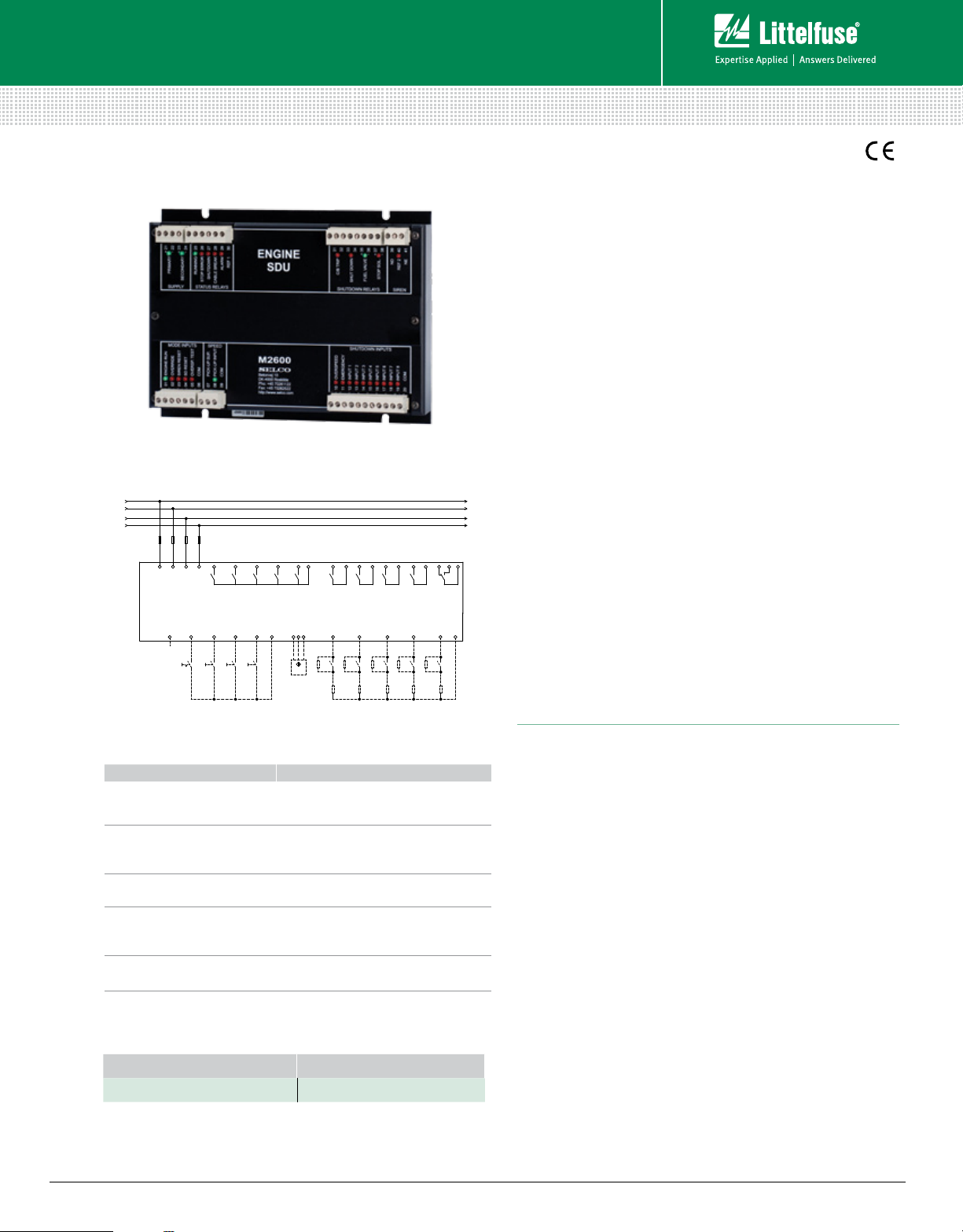
Simplified Circuit Diagram
PRIMARY +24 V
PRIMARY -
SECONDARY +24 V
SECONDARY -
OUTPUTS
INPUTS
2122232425
PRIMARY SUPPLY
1
S1 S2 S3 S4
SECONDARY SUPPLY
2
OVERRIDE
RUNNING
3
SIREN RESET
26
STOP ERROR
4
SD RESET
27
SHUTDOWN
5
OVERSPEED
TEST
282930
COM
CABLE BREAK
M2600
(Shut-Down Unit)
678
PICK-UP
ALARM
?
3132333435363738394041
C/B TRIP
9
10
EMERGENCY
STOP
11
COOLANT
TEMP.
SHUT DOWN
FUEL VALVE
12
COOLANT
LEVEL
STOP SOLENOID
13
LUBE OIL
PRESS.
14
FUEL OIL
LEAK.
Description
The M2600 Shutdown Unit is a back-up protection device
designed for marine engines. It is ensuring safety shutdown
of the engine in case normal primary shutdown fails. Together
with Engine controller units M2000 or M2500 or other
engine controllers it can be used to build a complete control,
alarm and safety system for marine engines. Alternatively
it can work as a standalone primary shutdown unit in
applications where shutdown functionality is not included
in the start/stop device of the engine. The M2600 design is
based entirely on discreet logic, thus meeting requirements
to safety shutdown devices from the marine classification
societies.
All inputs and outputs of the M2600 have corresponding LED
indication clearly showing whether they are active or not.
The unit furnishes 10 digital shutdown inputs. One is predefined for overspeed and another for emergency stop. All
inputs are dry contacts. Output relays are provided for control
of the fuel valve and the stop solenoid when stopping the
engine in normal conditions. Another output relay is provided
for emergency shutdown. Additionally the unit provides an
output for circuit breaker trip for use with gen-sets. Engine
COM
SIREN RELAY
15
speed (rpm) can be detected from magnetic and inductive
pick-ups connected to dedicated inputs. Alternatively the
speed can be detected from digital inputs. M2600 provides
cable monitoring on all sensor inputs and for the shutdown
relay output. Configuration is made solely with the dipswitches and rotary switches on the unit.
Features & Benefits
FEATURES BENEFITS
10 digital shutdown inputs
with cable monitoring
Speed detection
via magnetic or
inductive pick-up
LEDs for status indication
Cable monitoring on
fuel valve and
stop solenoid output
Configuration by
DIP switches
Ordering Information
ORDERING NUMBER REQUIREMENT
M2600.0010 Optional
© 2013 Littelfuse Protection Relays & Controls
www.littelfuse.com/m2600
Monitoring of e.g. oil pressure, coolant
temperature and engine speed
No tacho relay required
Easy overview of engine condition and
operation
Fail safe system, no need of separate cable
monitoring module
Easy installation and configuration
Specifications
Operating Temp. –15°C to +70°C
Humidity 95%
Vibration DNV vibrations class B
EMC IEC 60945
Enclosure IP30
Primary Supply +24 Vdc (-30 %/+30 %) <3 W
Backup Supply +24 Vdc (-30 %/+30 %) <3 W
Connection Screw terminals
Type Magnetic (2-wire), NPN and PNP (3-wire)
Rated Frequency 25.0-25,000 Hz
9 Digital Sensor Inputs Normally open contacts to COM (default) or
normally closed contacts to COM.
Optional cable monitoring.
All Relays except where otherwise specified
Relay Response Time 20 ms (worst case)
Contact set(s) 1 normally open
Contact rating AC: 1 A, 250 Vac; DC: 1 A, 35 Vac
Run/ Stop Solenoid relay
Relay Response Time 20 ms (worst case)
Contact Set(s) 1 normally open
Contact rating: AC: 8 A, 250 Vac; DC: 8 A, 35 Vdc
System fault output relay (Siren)
Relay response time 20 ms (worst case)
Contact set(s) 1 change over
Contact rating: AC: 1 A, 250 Vac; DC: 1 A, 35 Vdc
Dimensions H 157 mm (6.2”); W 210 mm (8.3”);
D 52 mm (2.0”)
Rev: 4-A-050313
 Loading...