

Page 1
LR Series
POLYFUSE® Resettable PTCs
POLYFUSE® Resettable PTCs
Axial Lead Battery Strap Type > LR Series
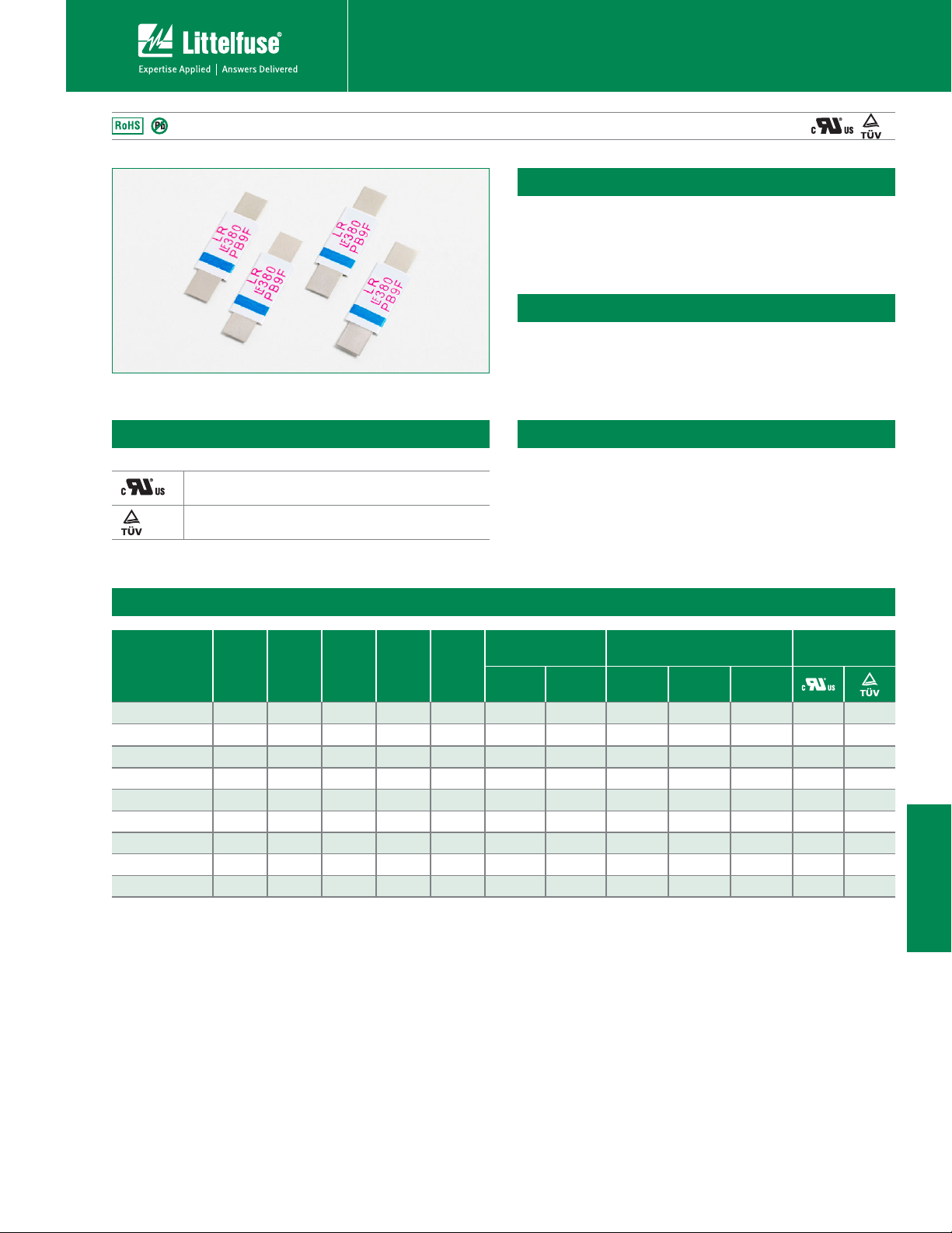
Description
The new LR Series device provides reliable, noncycling
protection against overcharging and short circuits events
for rechargeable battery cells where resettable protection
is desired.
Features
• RoHS compliant and
lead–free
• Weldable Nickel terminals
• Slim, low profile design
Agency Approvals
AGENCY AGENCY FILE NUMBER
E183209
Applications
• Rechargeable battery cell
protection
• Portable Computers
R50119583
Electrical Characteristics
Maximum Time
d
Current
(A)
To Trip
Time
(Sec.)
Part Number
I
hold
(A)
I
(A)
V
trip
(Vdc)
max
I
(A)
max
P
max.
(W)
15LR190 1.9 3.9 15 100 1.2 9.50 5.00 0.039 0.072 0.102
15LR190S 1.9 3.9 15 100 1.2 9.50 5.00 0.039 0.072 0.102
15LR260 2.6 5.8 15 100 2.5 13.00 5.00 0.020 0.042 0.063
15LR260S 2.6 5.8 15 100 2.5 13.00 5.00 0.020 0.042 0.063
15LR380 3.8 8.3 15 100 2.5 19.00 5.00 0.013 0.026 0.037
20LR450 4.5 8.9 20 100 2.5 22.50 5.00 0.011 0.020 0.028
20LR550 5.5 10.5 20 100 2.8 27.50 5.00 0.009 0.016 0.022
20LR600 6.0 11.7 20 100 2.8 30.00 5.00 0.007 0.014 0.019
20LR730 7.3 14.1 20 100 3.3 30.00 5.00 0.006 0.012 0.015
I
= Hold current: maximum current device will pass without tripping in 20°C still air.
hold
= Trip current: minimum current at which the device will trip in 20°C still air.
I
trip
= Maximum voltage device can withstand without damage at rated current (I max)
V
max
= Maximum fault current device can withstand without damage at rated voltage (V
I
max
= Power dissipated from device when in the tripped state at 20°C still air.
P
d
= Minimum resistance of device in initial (un-soldered) state.
R
min
)
max
= Typical resistance of device in initial (un-soldered) state.
R
typ
= Maximum resistance of device at 20°C measured one hour after tripping or reflow
R
1max
soldering of 260°C for 20 sec.
Caution: Operation beyond the specified rating may result in damage and possible arcing
and flame.
R
(Ω)
min
Resistance
R
typ
(Ω)
• Compact design saves
board space
• Low resistance
• Fast trip time
• Camcorders
Agency
Approvals
R
1max
(Ω)
XX
XX
XX
XX
XX
XX
XX
XX
XX
LR Series
© 2010 Littelfuse, Inc
Specifications are subject to change without notice.
Please refer to www.littelfuse.com/series/LR.html for current information.
113
Revised: June 4, 2010
LR Series
Page 2
POLYFUSE® Resettable PTCs
Axial Lead Battery Strap Type > LR Series
Temperature Rerating
Ambient Operation Temperature
-40°C -20°C 0°C 23°C 40°C 50°C 60°C 70°C 85°C
Part Number Hold Current (A)
15LR190 2.80 2.50 2.30 1.90 1.60 1.50 1.40 1.20 1.00
15LR190S 2.80 2.50 2.30 1.90 1.60 1.50 1.40 1.20 1.00
15LR260 3.80 3.40 3.10 2.60 2.20 2.00 1.90 1.70 1.40
15LR260S 3.80 3.40 3.10 2.60 2.20 2.00 1.90 1.70 1.40
15LR380 5.50 4.90 4.40 3.80 3.30 3.00 2.80 2.50 2.10
20LR450 6.50 5.80 5.30 4.50 3.90 3.60 3.30 2.90 2.50
20LR550 8.00 7.10 6.20 5.50 4.70 4.30 4.00 3.60 3.00
20LR600 8.70 7.80 7.10 6.00 5.20 4.70 4.40 3.90 3.30
20LR730 10.60 9.50 8.60 7.30 6.30 5.70 5.40 4.70 4.00
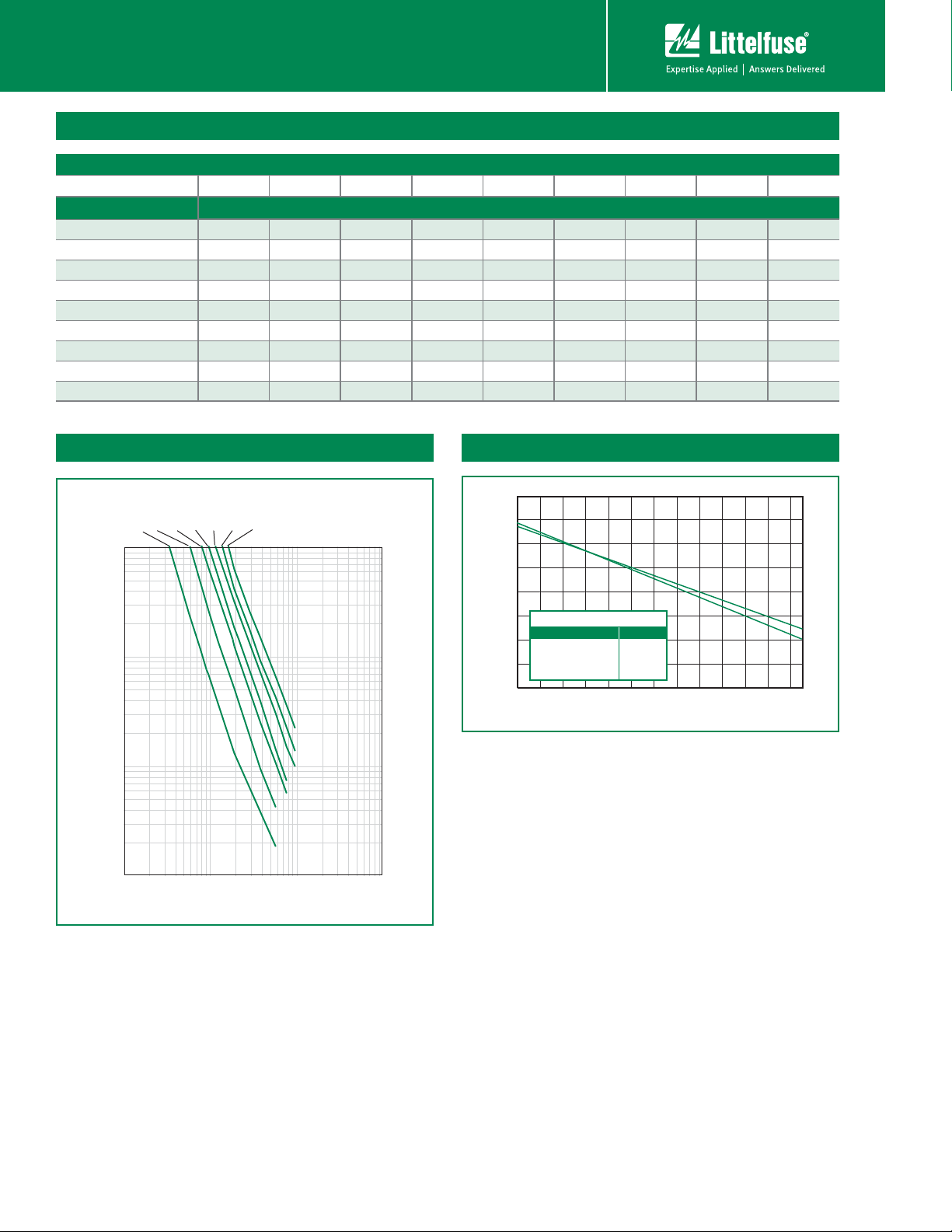
Average Time Current Curves
1.90 A
2.60 A
3.80 A
4.50 A
5.50 A
6.00 A
10
1
Time in Seconds
0.1
0.01
1 10 100 1000
Current in Amperes
7.30 A
LR
Temperature Rerating Curve
170%
150%
B
A
130%
110 %
90%
70%
50%
Percentage of Rated Current
30%
10%
Line/Part Number:
A
15LR190
• 15LR260
15LR190S
• 15LR260S
15LR260
• 15LR450
-40 -30 -20 -10 0 10 20 30 40 50607080
B
15LR380
15LR550
15LR600
20LR730
Temperature (°C)
A
B
The average time current curves and Temperature Rerating curve performance is affected
by a number or variables, and these curves provided as guidance only. Customer must
verify the performance in their application.
LR Series
Revised: June 4, 2010
114
© 2010 Littelfuse, Inc.
Please refer to www.littelfuse.com/series/LR.html for current information.
Specifications are subject to change without notice.
Page 3

POLYFUSE® Resettable PTCs
POLYFUSE® Resettable PTCs
Axial Lead Battery Strap Type > LR Series
Physical Specifications
Terminal Material
Insulating Material Polyester tape
0.13mm nominal thickness, quarter-hard
Nickel
Dimensions
B
D1 D2
Figure 1
A
Environmental Specifications
Operating/Storage
Temperature
Maximum Device Surface
Temperature in Tripped State
Passive Aging
Humidity Aging
Vibration
Figure 2
(Items with S at end of part number)
0.5 x 4.0
(.02”x .15”)
NOMINAL
A
SLIT
E
C
B
D1 D2
-40°C to +85°C
125°C
+70°C, 1000 hours
-/+10% typical resistance change
+85°C, 85% R.H., 7 days
-/+5% typical resistance
change
MIL–STD–883C, Method
2007.1, Condition A, No change
E
C
Part
Number
Figure
Inches mm Inches mm Inches mm Inches mm Inches mm Inches mm
Min. Max. Min. Max. Min. Max. Min. Max. Min. Max. Min. Max. Min. Min. Min. Min. Min Max. Min. Max.
15LR190 1 0.78 0.87 19.90 22.10 0.19 0.22 4.90 5.50 0.02 0.04 0.60 1.00 0.22 5.50 0.22 5.50 0.01 0.22 3.90 4.10
15LR190S 2 0.78 0.87 19.90 22.10 0.19 0.22 4.90 5.50 0.02 0.04 0.60 1.00 0.22 5.50 0.22 5.50 0.01 0.22 3.90 4.10
15LR260 1 0.82 0.91 20.90 23.10 0.19 0.22 4.90 5.50 0.02 0.04 0.60 1.00 0.16 4.10 0.16 4.10 0.01 0.16 3.90 4.10
15LR260S 2 0.82 0.91 20.90 23.10 0.19 0.22 4.90 5.50 0.02 0.04 0.60 1.00 0.16 4.10 0.16 4.10 0.01 0.16 3.90 4.10
15LR380 1 0.94 1.02 24.00 26.00 0.27 0.30 6.90 7.50 0.02 0.04 0.60 1.00 0.16 4.10 0.16 4.10 0.01 0.16 4.90 5.10
20LR450 1 0.94 1.02 24.00 26.00 0.39 0.41 9.90 10.50 0.02 0.04 0.60 1.00 0.21 5.30 0.21 5.30 0.01 0.21 5.90 6.10
20LR550 1 1.38 1.46 35.00 37.00 0.27 0.30 6.90 7.50 0.02 0.04 0.60 1.00 0.21 5.30 0.21 5.30 0.01 0.21 4.90 5.10
20LR600 1 0.94 1.02 24.00 26.00 0.55 0.57 13.90 14.50 0.02 0.04 0.60 1.00 0.16 4.10 0.16 4.10 0.01 0.16 5.90 6.10
20LR730 1 1.07 1.15 27.10 29.10 0.55 0.57 13.90 14.50 0.02 0.04 0.60 1.00 0.16 4.10 0.16 4.10 0.01 0.16 5.90 6.10
Part Marking System
ABCD1D2E
Littelfuse
Trademark
Top Side
LR
190S
XX9R
Product Series
Current Rating
Lot Number
(Contact Littelfuse
for additional
information)
LR Series
© 2010 Littelfuse, Inc
Specifications are subject to change without notice.
Please refer to www.littelfuse.com/series/LR.html for current information.
115
Revised: June 4, 2010
LR Series
Page 4
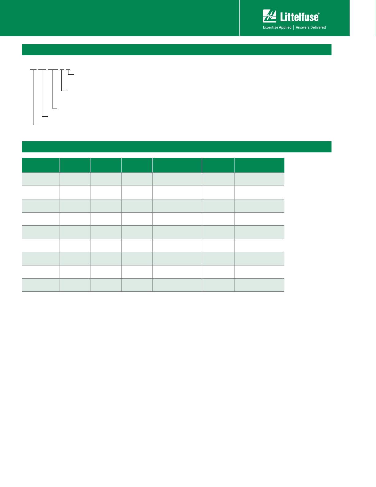
Part Ordering Number System
15 LR 190 S U
QUANTITY CODE
U: 500 (bulk)
POLYFUSE® Resettable PTCs
Axial Lead Battery Strap Type > LR Series
LEAD OPTIONS:
HOLD CURRENT (VALUE DIVIDED BY 100 = HOLD CURRENT IN AMPS)
SERIES
Voltage Rating (VDC)
Packaging
Part Number
15LR190 15LR190U
15LR190S 15LR190SU
15LR260 15LR260U
15LR260S 15LR260SU
15LR380 15LR380U
20LR450 20LR450U
20LR550 20LR550U
Ordering
Number
Blank = standard
S = slit lead
I
hold
(A)
I
Code
hold
Packaging
Option
Quantity
Quantity &
Packaging Codes
1.9 190 Bulk 500 U
1.9 190 Bulk 500 U
2.6 260 Bulk 500 U
2.6 260 Bulk 500 U
3.8 380 Bulk 500 U
4.5 450 Bulk 500 U
5.5 550 Bulk 500 U
20LR600 20LR600U
20LR730 20LR730U
6.0 600 Bulk 500 U
7.3 730 Bulk 500 U
LR Series
116
Revised: June 4, 2010
© 2010 Littelfuse, Inc.
Please refer to www.littelfuse.com/series/LR.html for current information.
Specifications are subject to change without notice.
 Loading...