

Littelfuse MiniFlec Series, LFMX0007Z-01 Installation Sheet
Installation Instructions
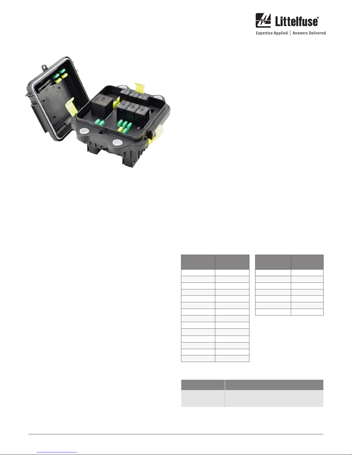
MiniFlec Series Power Distribution Module
Part Number: LFMX0007Z-01
Specifications Overview
Max Load: 150 A
Fuse Rating Ranges: MINI® Fuse: 2-30A
MCASE+® Fuse: 15-60A
Color: Black
Housing: Glass Renforces Nylon (94V-0)
Ingress Protection: IEC 529 IP67/69K
Input Stud: M8
Mating Terminals & Seals Tyco HDSCS Series Connectors
with MCP Terminals
Tyco 1-15 64542-1
Tyco 1-14184 37-1
Tyco 2-1564514-1
Tyco 1-16 708 94 -1
LFMX0006Z-01
Description
The standard MiniFlec is a compact, front access, internally
bussed, connectorized, sealed power distribution module,
suitable for mounting in rugged commercial vehicle
applications. The MiniFlec is a product that has dense
concentration of high power circuits and accepts plug devices
like automotive fuses, diodes and relays to protect and control
complex electrical systems. An internally mounted Printed
Circuit Board (PCB) allows bussed connections to a large
number of devices.
Working Voltages: 9-16V with 12V Relays
18-32V with 24V Relays
Input Stud Torque: 12-15 Nm
Mounting Bolt Torque: 12-15 Nm
Vibration Resistance: ISO 16750-4
Operating Temp: -40°C to +85°C
Dimensions (LxWxH): 157mm x 96mm x 126mm
Accessories: Fuse Puller, Spare Fuses Tether
Relay Capacity: 3 Form C 280 Series Micro Relays,
3 Form A Ultra Micro Relays,
1 ISO Micro Relay
Installation
Assemble the PDM and mount to a surface following the
below sequence:
1. Fill the available fuse and relay spots to match the the
application needs. Check the locations on the fuse and
relay table for the maximum fuse and relay ratings for
each space and do not exceed the maximum rated values.
2. Use the mounting hole pattern on the mounting surface
and mark the mounting hole pattern. Drill the holes so
they are sized for M6 bolts. Place the MiniFlec over the
pattern and bolt it in place. Torque down the mounting
screws to 12-15Nm (4.5-5.9 ft-lb).
3. The harnesses should be made to match the terminal
map on the schematic. The connectors should now be
attached. Each has a unique key that should prevent
misassembly. Make certain that the connectors are fully
inserted and the secondary lock is fully engaged. If the
secondary lock will not fully engage, the connector is not
fully connected. Be sure that the output cables are routed
so they have sufficient bend radius and are not at risk
of being damaged or pinched. Lastly, make sure that all
cables are strain relieved by being supported within 18”
of the battery.
Step by step images shown in Figure 1 on page 2.
FUSE
LOCATION
F01 30A
F02 30A
F03 30A
F04 20A
F05 20A
F06 20A
F07 50A MCASE
F08 30A
F09 20A
F10 30A
F11 30A
F12 30A
F13 60A MCASE
F14 20A
MAX FUSE
VALUE
RELAY
LOCATION
K01 35A
K02 35A
K03 35A
K04 20A
K05 20A
K06 20A
K07 40A
MAX RELAY
VALUE
Ordering Information
PART NUMBERS DESCRIPTION
LFLM0007Z-01
A custom MiniFlec can be built specific to your design
requirements and is a special order product. Please talk to
your local representative for additional details.
Standard Unloaded MiniFlec Power
Distribution Module
littelfuse.com
1 of 3
Rev: 081718© 2018 Littelfuse Commercial Vehicle Products
Installation Instructions
MiniFlec Series Power Distribution Module
Part Number: LFMX0007Z-01
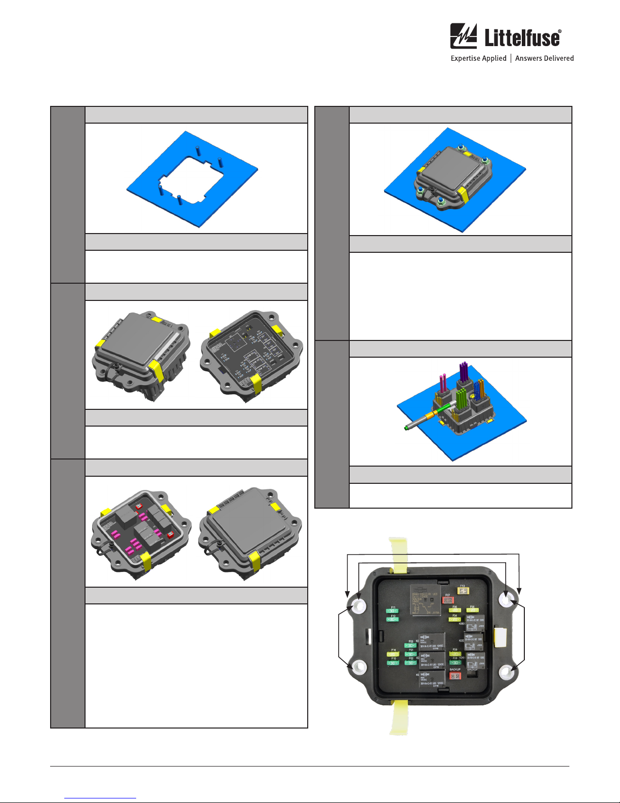
Figure 1 - Step by Step Installation
STEP
1
STEP
2
IMAGE
DETAILS
Cut the panel per the mounting hole pattern and
place the mounting bolts into the locations on the
panel.
IMAGE
IMAGE
STEP
4
DETAILS
Bring the main power cable through the cutout
and attach the ring terminal to the main M8 power
stud. Run the harness with the connectors through
the mounting hole and attach the connectors to
the appropriate point. All the connectors are keyed
and cannot be assembled to an incorrect location.
Press the connectors into the mating connector
locations and make sure they are fully seated and
the secondary lock is closed.
IMAGE
STEP
3
DETAILS
Take the unit out of the packaging. Snap open
the AssureLatch latches with a small flathead
screwdriver or other tool. Remove the cover.
IMAGE
DETAILS
Fill in all fuse locations with application specific
fuses make sure not to exceed the maximum value
for the fuse locations as listed in fuse table. Fill the
application specific relays using the recommended
types of relays. There is a location on the inside
cover to place a fuse identification label. We
recommend you add a label here to help with
maitenance and troubleshooting. Replace the cover
and snap on the AssureLatch latches. If you do not
get positive tactile and audible feedback that the
latches are fully seated, check the position of the
cover. The box is only seated correctly and sealed
when laches are properly snapped into place.
STEP
5
DETAILS
Put the MiniFlec into the cut out and tighten the
mounting bolts to 12-15Nm.
Mounting Pattern Diagram
157mm
133mm
55mm
65mm
Specifications, descriptions and illustrative material in this literature are as accurate as known at the time of publication,
but are subject to changes without notice. Visit littelfuse.com for the most up-to-date technical information.
littelfuse.com
2 of 3
Rev: 081718© 2018 Littelfuse Commercial Vehicle Products
 Loading...