

Page 1
Teccor® brand Thyristors
Multipulse™ SIDACs
Kxxx1G Series
Schematic Symbol
Applications
RoHS
Description
The Multipulse™ SIDAC is a voltage switch used in MetalHalide lamp ignition circuits as well as High Pressure
Sodium lamp ignition circuits for outdoor street and area
lighting. This robust solid state switch is designed to handle
lamp igniter applications requiring operation at ambient
temperatures up to 90°C where igniter circuit components
can raise SIDAC junction temperature up to 125°C, especially
when the lamp element is removed or ruptured. Its excellent
commutation time (t
suited for producing multiple pulses in each half cycle of
50/60 Hz line voltage. The Multipulse
) makes this robust product best
COMM
™
SIDAC is offered in
DO-15 axial leaded package.
Kxxx1G SIDAC has a repetitive off-state blocking voltage
(V
) of 180V to 270V minimum depending actual device
DRM
type. Blocking capability is ensured by glass passivated
junctions for best reliability. Package is epoxy encapsulation
with tin-plated copper alloy leads.
Features
• AC circuit oriented
RoHS
• Compliant
• Triggering Voltage of 200
to 380V
Typical application circuit presented in Figure 10 of this data
sheet (Typical Metal Halide Ignitor Circuit).
Electrical Specifications
Symbol Parameters Test Conditions Min Max Unit
K2201G
V
BO
Breakover/Trigger Voltage
K2401G
K2501G
K3601G
K2201G
V
DRM
Repetitive Peak Off-State Voltage
K2401G
K2501G
K3601G
I
T(RMS)
I
H
R
S
t
COMM
I
BO
I
TSM
On-State RMS Current, TJ < 125ºC
Dynamic Holding Current, R=100 Ω
Switching Resistance, RS=
(IS – IBO)
(VBO – VS)
________
Commutation Time TJ < 125ºC
Breakover Current
Non-repetitive 1 cycle On-State peak value
50/60Hz
Sine Wave
50/60Hz
Sine Wave
50/60Hz
Sine Wave
See test circuit and
waveform in Figure 9
50/60Hz
Sine Wave
60Hz
50Hz
di/dt Critical Rate of Rise of On-State Current 150 A/μsec
dv/dt Critical Rate of Rise of Off-State Voltage 150 0 V/μsec
T
S
T
J
R
θJL
Storage Temperature Range -40 +125 °C
Max Operating Junction Temperature -40 +125 °C
Thermal Resistance Junction to lead 18 °C/W
200
220
240
340
230
250
280
380
V
180
190
200
V
270
1 A
120 TYP mA
100 Ω
100 μsec
10 uA
20.0
16.7
A
Kxxx1G Series
1
Specifications are subject to change without notice.
©2013 Littelfuse, Inc
Revised: 12/26/13
Page 2
Teccor® brand Thyristors
81
Multipulse™ SIDACs
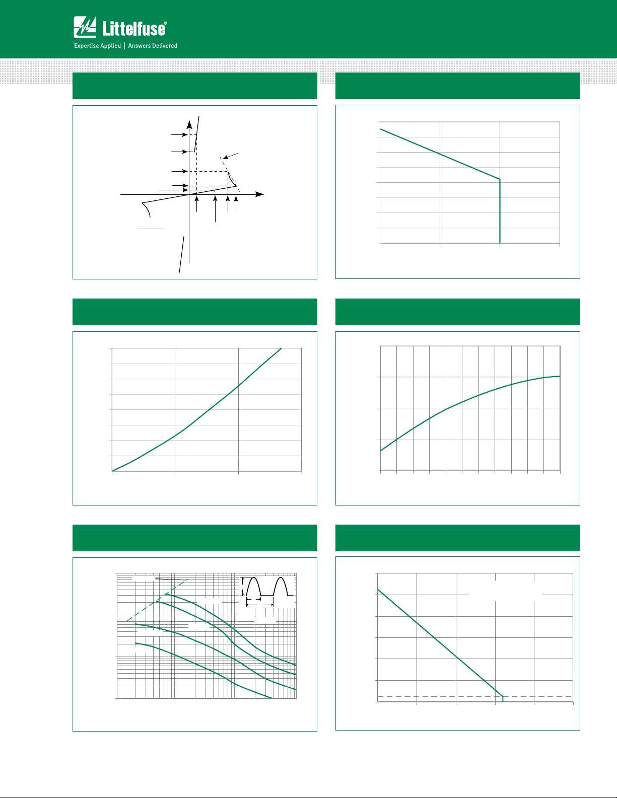
Figure 1: Characteristics
+I
I
T
I
H
I
S
I
BO
I
R
=
S
DRM
(VBO - VS)
- IBO)
(I
S
V
V
T
V
DRM
-V
-I
Figure 3: Power Dissipation (Typical)
vs. On-State Current
4.0
3.5
3.0
2.5
(Watts)
D
2.0
1.5
Average P
1.0
0.5
0.0
RMS On-State Current (Amps)
Figure 2: Maximum Allowable Lead/Tab Temperature
vs. On-State Current
130
120
R
S
+V
V
BO
S
110
100
90
80
Te mperature (°C)
70
Maximum Allowable Lead
60
50
2.01.51.00
RMS On-State Current (Amps)
Figure 4: VBO Change
vs. Junction Temperature
10.0
BO
5.0
0.0
Change (%)
-5.0
Normalized Percentage of V
-10.0
1.51.00.50.0
-40 -25 -10520 35 50 65 80 95 110125
Junction Temperature (°C)
Figure 5: Pulse On-State
Current Rating
1000
di/dt limit
100
)-Amps
TRM
10
Current (I
Repetitive Peak On-State
1
Kxxx1G Series
1KHz
5KHz
110 100 1000
f = 5Hz
60 Hz
Pulse Base Width (tO)-µs
Figure 6: Maximum Allowable Ambient Temperature
vs. On-State Current
140
I
TM
t
O
1/f
TJ=125˚C
120
100
80
) - °C
A
(T
60
40
25
Maximum Allowable Ambient Te mperature
20
0.00.2 0.40.6 0.
RMS On-State Current [I
2
CURRENT WAVEFORM: Sinusoidal - 60Hz
LOAD: Resistive or Inductive
FREE AIR RATING
] - Amps
T(RMS)
Specifications are subject to change without notice.
©2013 Littelfuse, Inc
.0
Revised: 12/26/13
Page 3

Teccor® brand Thyristors
Multipulse™ SIDACs
Figure 7: Peak Surge Current vs Surge Current Duration
100
40
] – Amps
20
TSM
10
Peak Surge (Non-repetitive)
On-state Current [I
0
010100 1000
Surge Current Duration – Full Cycles
Figure 8: Typical On-State Voltage vs On-State Current
10
SUPPLY FREQUENCY: 60 Hz Sinusoidal
LOAD: Resistive
RMS On-State Current: I
Specified Junction Temperature
Notes:
1. Blocking capability may be lost during
and immediately following surge
current interval.
2. Overload may not be repeated until
junction temperature has returned
to steady-state rated value.
Figure 9: Multipulse™ SIDAC t
1Mohm 30uH
i
SIDAC
320VDC
(nominal)
0.2uF
L6008V6
Maximum Rated Value at
T
, Commutation Time
COMM
DUT
300ohm
(A)
T
1
Instantaneous On-State Current i
0.1
1.21.6 2 2.4 2.8 3.2 3.6
Instantaneous On-State Vo ltage vT (V)
6V, 500us
SIDAC Commutation Time Test Circuit
i
125°C25°C
SIDAC
25A
time
~10μs
commutation time, t
comm
SIDAC Current Response Waveform
Kxxx1G Series
3
Specifications are subject to change without notice.
©2013 Littelfuse, Inc
Revised: 12/26/13
Page 4

Teccor® brand Thyristors
eat
Ramp-do
Multipulse™ SIDACs
Figure 10: Typical Metal Halide Ignitor Circuit
H.V.
Step-up
Ballast
Transformer
0.1-0.15 µF
220 V / 240 V
50 / 60 Hz
0.22- 0.33µF
Note: With proper component selection, this circuit will produce three pulses for ignition of
metal halide lamp that requires a minimum of three pulses at 4kV magnitude and >1uSec
duration each at a minimum repetition rate of 3.3kHz.
Kxxx1G
5-6µH
5.6K- 8.2K
5W
Metal
Halide
Lamp
Soldering Parameters
Reflow Condition Pb – Free assembly
- Temperature Min (T
Pre Heat
- Temperature Max (T
- Time (min to max) (ts) 60 – 180 secs
Average ramp up rate (Liquidus Temp)
(TL) to peak
T
to TL - Ramp-up Rate 5°C/second max
S(max)
Reflow
- Temperature (TL) (Liquidus) 217°C
- Temperature (tL) 60 – 150 seconds
Peak Temperature (TP) 260
Time within 5°C of actual peak
Temperature (tp)
Ramp-down Rate 5°C/second max
Time 25°C to peak Temperature (TP) 8 minutes Max.
Do not exceed 280°C
) 150°C
s(min)
) 200°C
s(max)
5°C/second max
+0/-5
°C
20 – 40 seconds
T
P
T
L
T
S(max)
Temperature
T
S(min)
25
Ramp-upRamp-up
PreheatPreh
t
S
time to peak temperature
t
P
t
L
Ramp-down
Time
Kxxx1G Series
4
Specifications are subject to change without notice.
©2013 Littelfuse, Inc
Revised: 12/26/13
Page 5

Teccor® brand Thyristors
Multipulse™ SIDACs
Physical Specifications Reliability/Environmental Tests
Terminal Finish 100% Matte Tin Plated
Body Material
UL recognized epoxy meeting flammability
classification 94V-0
Lead Material Copper Alloy
Package Weight / unit (mg)
DO-15 385
Design Considerations
Careful selection of the correct device for the application’s
operating parameters and environment will go a long
way toward extending the operating life of the Thyristor.
Overheating and surge currents are the main killers of
SIDACs. Correct mounting, soldering, and forming of the
leads also help protect against component damage.
Test
High Temperature
Voltage Blocking
Temperature Cycling
Temperature /
Humidity
High Temp Storage
Specifications and Conditions
MIL-STD-750: Method 1040, Condition
A Rated V
hours
(VAC-peak), 125°C, 1008
DRM
MIL-STD-750: Method 1051, 100 cycles;
-40°C to 150°C, 15-minute dwell time
EIA/JEDEC: JESD22-A101
1008 hours; 160V - DC: 85°C;
85% relative humidity
MIL-STD-750: Method 1031
150°C, 1008 hours
Low-Temp Storage -40°C, 1008 hours
MIL-STD-750: Method 1056
Thermal Shock
10 cycles; 0°C to 100°C; 5-minute dwelltime at each temperature; 10-sec (max)
transfer time between temperature
Autoclave
EIA/JEDEC: JESD22-A102
168 hours (121°C at 2 ATMs) and
100% RH
Resistance to
Solder Heat
MIL-STD-750: Method 2031
260°C, 10 seconds
Solderability ANSI/J-STD-002: Category 3, Test A
Repetitive Surge
Life Testing
Multi firings per half cycle at 60Hz in
application circuit for 168 hours minimum
Dimensions — DO-15 (G Package)
Dimension
D
B
B 0.028 0.034 0.711 0.864
D 0.120 0.140 3.048 3.556
L
G
L
G 0.235 0.270 5.969 6.858
L 1.000 25.400
Inches Millimeters
Max Max Min Max
Product Selector
Part Number
K2201G 200V 230V 180V DO-15
K2401G 220V 250V 190V DO-15
K2501G 240V 280V 200V DO-15
K3601G 340V 380V 270V DO-15
Switching Voltage Range Blocking Voltage
VBO Minimum VBO Maximum V
DRM
Packages
Kxxx1G Series
5
Specifications are subject to change without notice.
©2013 Littelfuse, Inc
Revised: 12/26/13
Page 6

Teccor® brand Thyristors
DO-15
Multipulse™ SIDACs
Packing Options
Part Number Package Packing Mode Base Quantity
Kxxx1G
DO-15
Kxxx1GRP Tape & Reel 5000
Note: xxx = voltage
DO-15 Embossed Carrier RP Specifications
Meets all EIA RS-29-6 Standards
DO-15
2.063
(52.4)
0.898
(22.8)
Bulk 1000
(254.0 - 356.0)
3.15 (80.0) TYP
10.0 - 14.0
Dimensions
are in inches
(and millimeters).
0.252
(6.4)
Part Numbering System
K
220 1
SERIES
K: Sidac
VOLTAGE
220: 200 to 230V
240: 220 to 250V
250: 240 to 280V
360: 340 to 380V
CIRCUIT FUNCTION
1: Multipulse
™
0.197
(5.0)
G
RP
PACKAGING OPTIONS
Blank: Bulk
RP: Tape and Reel
DEVICE PACKAGE
G: DO-15
Part Marking System
Kxxx1G
YMXXX
®
Direction of Feed
Kxxx1G Series
6
Specifications are subject to change without notice.
©2013 Littelfuse, Inc
Revised: 12/26/13
 Loading...