

Page 1
Teccor® brand Thyristors
High Energy Bidirectional SIDACs
Kxxx0yH Series
Schematic Symbol
RoHS
Description
The new Kxxx0yH is a higher energy SIDAC switch for gas
ignition applications requiring higher current pulse current
especially at low repetition rate. It is offered in a DO-15 and
TO-92 leaded packages as well as DO-214 surface mount
package. Voltage activation of this solid state switch is
accomplished with peak voltage level of 190 to 280Volts. The
SIDAC is a silicon bilateral voltage triggered Thyristor switch
that switches on through a negative resistance region to a
low on-state voltage. Conduction will continue until current
is interrupted or lowered below minimum holding current of
the device.
Features
• AC Circuit Oriented
• Triggering Voltage of 190
to 280V
• 280A Pulse Current
Capability
• RoHS Compliant
Applications
Suitable for high voltage power supplies, natural gas
igniters, and Xenon flash ignition.
Electrical Specifications (T
= 25°C, unless otherwise specified)
J
Symbol Parameters Test Conditions Min Max Unit
K2000yH 190 215
V
BO
Breakover/Trigger Voltage
K2200yH 205 230
K2400yH 220 250
K2500yH 240 280
K2000yH 180
V
DRM
Repetitive Peak Off-state Voltage
K2200yH 180
K2400yH 190
K2500yH 200
I
T(RMS)
V
TM
I
H
R
S
I
BO
I
TRM
On-state RMS Current
Peak On-state Voltage
Dynamic Holding Current
Switching Resistance, RS=
(VBO – VS)
________
(IS – IBO)
Breakover Current 50/60Hz Sine Wave 50 μA
Peak Repetitive Pulse Current
(refer to figure 4)
50/60Hz, T
50/60Hz Sine Wave
50/60Hz Sine Wave 100 Ω
tp = 10μs
< 125°C
J
= 1A
I
T
RL = 100Ω
1 A
1. 5 V
150 mA
60Hz 120
5Hz 280
di/dt Critical Rate of Rise of On-State Current 150 A/μs
dv/dt Critical Rate of Rise of Off-State Voltage 150 0 V/μs
T
S
T
J
R
θJL
R
θJC
R
θJA
Note: xxx - voltage, y = package
Kxxx0yH Series
Storage Temperature Range -40 150 °C
Junction Temperature Range -40 125 °C
Thermal Resistance, Junction to Lead
DO-15 18
DO-214 30
Thermal Resistance, Junction to Case TO-92 35 °C/W
Thermal Resistance, Junction to Ambient
1
DO-15 75
TO-92 95
Specifications are subject to change without notice.
©2013 Littelfuse, Inc
Revised: 12/26/13
V
V
A
°C/W
°C/W
Page 2
Teccor® brand Thyristors
01
cles
High Energy Bidirectional SIDACs
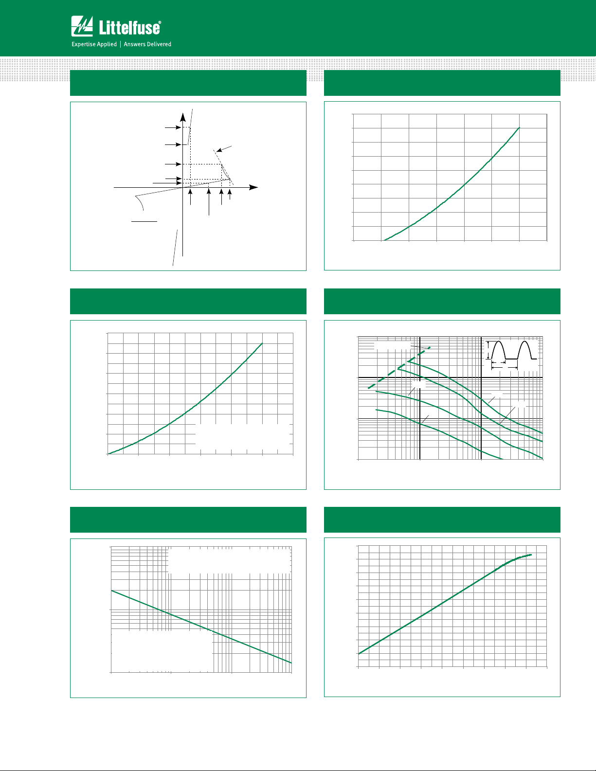
Figure 1: V-I Characteristics
+I
I
T
I
H
I
S
I
BO
I
-V
DRM
V
)
(V
BO-VS
R
=
S
(IS-IBO)
T
R
S
+V
V
BO
V
S
V
DRM
-I
Figure 3: Power Dissipation vs. On-state Current
(Typical)
1.2
1.0
0.8
] - Watts
0.6
D(AV)
[P
0.4
0.2
Average On-State Power Dissipation
0.0
0.0 0.2 0.4 0.6 0.8 1.
RMS On-State Current [I
CURRENT WAVEFORM: Sinusoidal
LOAD: Resistive or Inductive
CONDUCTION ANGLE:
See basic SIDAC circuit in Figure 12
] - Amps
T(RMS)
Figure 2: On-state Current vs. On-state
Voltage (Typical)
9
8
) – Amps
T
7
6
5
4
3
2
1
Instantaneous On-state Current (i
0
0.6 0.8 1. 01.2 1.41.6 1.8 2.0
Figure 4: Repetitive Peak On-state Current (I
Instantaneous On-state Voltage (vT) – Volts
TRM
)
vs. Pulse Width at Various Frequencies
1000
) - Amps
TRM
.2
Repetitive Peak On-State Current (I
di/dt Limit Line
100
10
1
110100 1000
1 kHz
5 kHz
I
TM
t
O
1/f
5 Hz
60 Hz
Pulse Base Width (tO) - us
Figure 5: Surge Peak On-state Current
vs. Number of Cycles
100
) – Amps
TSM
10
Peak Surge (Non-repetitive)
On-state Current (I
1
Kxxx0yH Series
Notes:
1) Blocking capability may be lost during
and immediately following surge
current interval.
2) Overload may not be repeated until
junction temperature has returned
to steady-state rated value.
110100 1000
SUPPLY FREQUENCY: 60 Hz Sinusoidal
LOAD: Resistive
RMS ON-STATE CURRENT: I
Value at Specified Junction Temperature
Surge Current Duration -- Full Cy
RMS Maximum Rated
T
Figure 6: Normalized VBO Change
vs. Junction Temperature
10%
8%
6%
4%
2%
0%
Change -- %
BO
V
-2%
-4%
-6%
-8%
-40 -20 020406080100 120140
Junction Temperature (TJ) -- °C
2
Specifications are subject to change without notice.
©2013 Littelfuse, Inc
Revised: 12/26/13
Page 3
Teccor® brand Thyristors
01
High Energy Bidirectional SIDACs
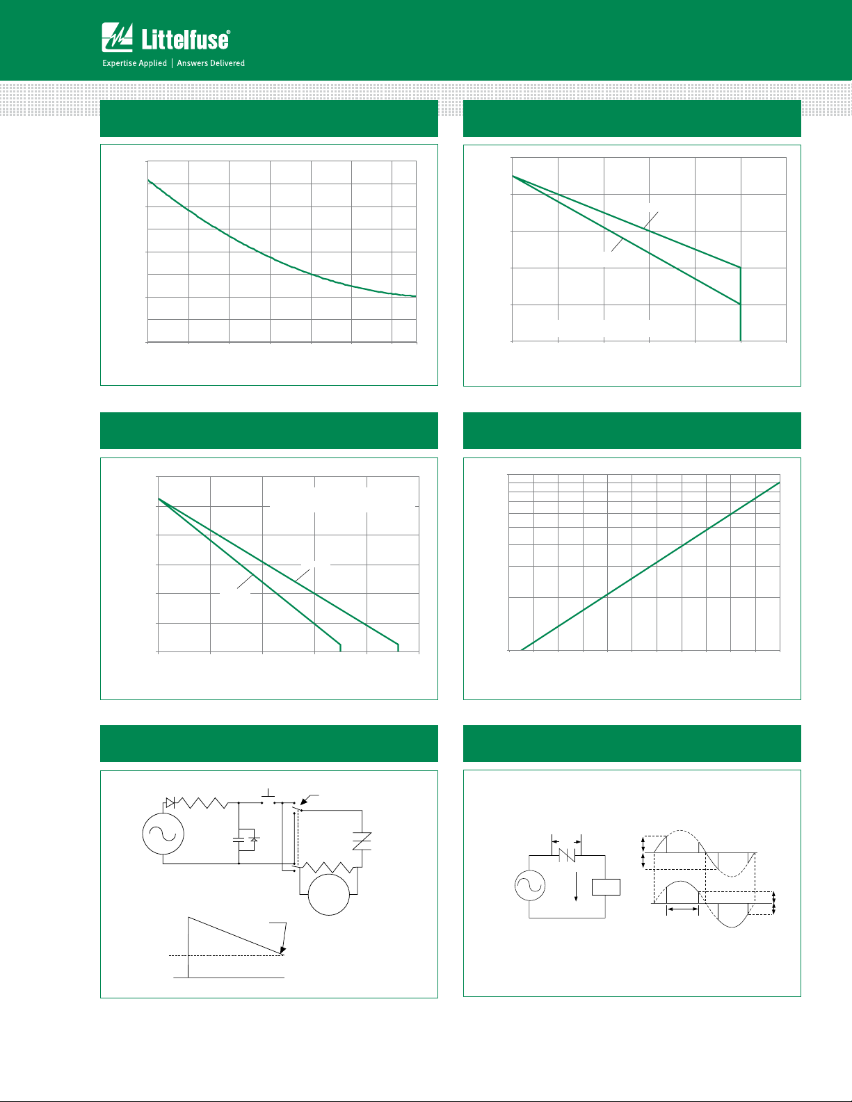
Figure 7: Normalized DC Holding Current
vs. Junction Temperature
2.0
1.5
= 25°C)
J
(T
H
1.0
/ I
H
0.5
Ratio of I
0.0
-40 -1510356085110
125
Junction Temperature (TJ) -- °C
Figure 9: Maximum Allowable Ambient Temperature
vs. RMS On-State Current
140
CURRENT WAVEFORM : Sinusoidal - 60Hz
120
LOAD: Re sistive or Inductive
FREE AIR RATING
Figure 8: Maximum Allowable Case Temperature
vs. RMS On-State Current
130
120
) - °C
C
110
100
Kxxx0SH
Kxxx0EH
Kxxx0GH
Temperature (T
90
Maximum Allowable Lead/Case
CURRENT WAVEFORM: Sinusoidal - 60Hz
LOAD: Resistive or Inductive
80
0.0 0.2 0.4 0.6 0.8 1.
RMS On-State Current [I
T(RMS)
] - Amps
Figure 10: Normalized Repetitive Peak Breakover
Current (I
10
) vs. Junction Temperature
BO
.2
100
) - °C
A
80
60
Temperature (T
Maximum Allowable Ambient
40
20
0.0 0.2 0.4 0.6 0.8 1.0
Kxxx0SH
Kxxx0EH
RMS On-State Current [I
Kxxx0GH
T(RMS)
] - Amps
Figure 11: Dynamic Holding Current Test
Circuit for SIDACs
I
H
100-250 V ac
60 Hz
I
PK
Push to test
Trace Stops
S1
S1
Switch to test
in each direction
100 Ω
1%
Scope
Device
Under
Test
) Multiplier
BO
Current (I
Repetitive Peak Breakover
1
20 30 40 50 60 70 80 90 100110 120130
Junction Temperature (TJ) -- °C
Figure 12: Basic SIDAC Circuit
V
100-250 V ac
60 Hz
BO
I
H
Load
V
BO
V
BO
Conduction
120-145
Angle
˚
Load Current
I
H
I
H
Kxxx0yH Series
Scope Indication
3
Specifications are subject to change without notice.
©2013 Littelfuse, Inc
Revised: 12/26/13
Page 4

Teccor® brand Thyristors
eat
Ramp-do
High Energy Bidirectional SIDACs
Figure 13: Relaxation Oscillator Using a SIDAC Figure 14: General Gas Ignitor Circuit
(a) Circuit
SCR Sidac
100-250 V ac
60 Hz
R
max
min
≤
≥
V
C
C
VIN-V
VIN-V
I
I
H (MIN)
SIDAC
I
L
BO
BO
TM
V
DC(IN)
≥ V
B0
R
R
Soldering Parameters
V
BO
V
C
R
L
I
L
(b) Waveforms
t
t
100-250 V ac
60 Hz
Reflow Condition Pb – Free assembly
Pre Heat
- Temperature Min (T
- Temperature Max (T
) 150°C
s(min)
) 200°C
s(max)
- Time (min to max) (ts) 60 – 180 secs
Average ramp up rate (Liquidus Temp)
(TL) to peak
T
to TL - Ramp-up Rate 5°C/second max
S(max)
Reflow
- Temperature (TL) (Liquidus) 217°C
- Temperature (tL) 60 – 150 seconds
Peak Temperature (TP) 260
Time within 5°C of actual peak
Temperature (tp)
5°C/second max
+0/-5
°C
20 – 40 seconds
Ramp-down Rate 5°C/second max
Time 25°C to peak Temperature (TP) 8 minutes Max.
Do not exceed 280°C
T
P
T
L
T
S(max)
Temperature
T
S(min)
25
Ramp-upRamp-up
PreheatPreh
t
S
time to peak temperature
t
P
t
L
Ramp-down
Time
Kxxx0yH Series
4
Specifications are subject to change without notice.
©2013 Littelfuse, Inc
Revised: 12/26/13
Page 5

Teccor® brand Thyristors
0.079
(2.0)
0.110
(2.8)
0.079
(2.0)
H
K
E
F
G
A
C
B
D
Case
Temperature
Measurement
Point
Soldering Pad Outline
inch
(millimeter)
Recommended
High Energy Bidirectional SIDACs
Physical Specifications Reliability/Environmental Tests
Terminal Material Copper Alloy
Terminal Finish
Body Material
100% Matte Tin-plated /Pb Free
solder dipped.
UL recognized epoxy meeting flammability
classification 94V-0.
Design Considerations
Careful selection of the correct device for the application’s
operating parameters and environment will go a long
way toward extending the operating life of the Thyristor.
Overheating and surge currents are the main killers of
SIDACs. Correct mounting, soldering, and forming of the
leads also help protect against component damage.
Dimensions — DO-214
Test
High Temperature
Voltage Blocking
Specifications and Conditions
MIL-STD-750: Method 1040, Condition
A Rated V
hours
(VAC-peak), 125°C, 1008
DRM
MIL-STD-750: Method 1051
Temperature Cycling
-40°C to 150°C, 15-minute dwell, 100
cycles
Biased Temperature &
Humidity
High Temp Storage
EIA/JEDEC: JESD22-A101
(VDC), 85°C, 85%RH, 1008 hours
MIL-STD-750: Method 1031
150°C, 1008 hours
Low-Temp Storage -40°C, 1008 hours
MIL-STD-750: Method 1056
Thermal Shock
0°C to 100°C, 5-minute dwell, 10-second
transfer, 10 cycles
Autoclave
(Pressure Cooker Test)
Resistance to
Solder Heat
EIA/JEDEC: JESD22-A102
121°C, 100%RH, 2atm, 168 hours
MIL-STD-750: Method 2031
260°C, 10 seconds
Solderability ANSI/J-STD-002: Category 3
Repetitive Surge
Life Testing
MIL-STD-750: Method 2036, Condition E
Dimension
Inches Millimeters
Max Max Min Max
A 0.130 0.156 3.30 3.95
B 0.201 0.220 5.10 5.60
C 0.077 0.087 1.95 2.20
D 0.159 0.181 4.05 4.60
E 0.030 0.063 0.75 1.60
F 0.075 0.096 1.90 2.45
G 0.002 0.008 0.05 0.20
H 0.077 0.104 1.95 2.65
K 0.006 0.016 0.15 0.41
Kxxx0yH Series
5
Specifications are subject to change without notice.
©2013 Littelfuse, Inc
Revised: 12/26/13
Page 6

Dimensions — DO-15
Teccor® brand Thyristors
High Energy Bidirectional SIDACs
Temperature Measuring Point
L
G
ØD
L
Dimensions - TO-92 with Type 70 Lead Form
Temperature Measuring Point
A
N
B
MT1
M
L
MT2
E
G
H
F
D
ØB
Dimension
ØB 0.028 0.034 0.711 0.864
ØD 0.120 0.140 3.048 3.556
Inches Millimeters
Max Max Min Max
G 0.235 0.270 5.969 6.858
L 1.000 25.400
Dimension
Inches Millimeters
Max Max Min Max
A 0.176 0.196 4.47 4.98
B 0.500 12.70
D 0.095 0.105 2.41 2.67
E 0.150 3.81
F 0.046 0.054 1.16 1.37
G 0.135 0.145 3.43 3.68
H 0.088 0.096 2.23 2.44
J 0.176 0.186 4.47 4.73
K 0.088 0.096 2.23 2.44
L 0.013 0.019 0.33 0.48
M 0.013 0.017 0.33 0.43
N 0.060 1.52
Notes:
1. Type 70 lead form as shown is standard for the E package.
2. All leads are insulated from case. Case is electrically nonconductive (rated at 16000V ac
rms for one minute from leads to case over the operating temperature range.)
3. Mold flash shall not exceed 0.13 mm per side.
Product Selector
Part Number
K2000yH 190V 215V 180V K2000GH K2000SH K2000EH70
K2200yH 205V 230V 180V K2200GH K2200SH K2200EH70
K2400yH 220V 250V 190V K2400GH K2400SH K2400EH70
K2500yH 240V 280V 200V K2500GH K2500SH K2500EH70
Note: y = package
Kxxx0yH Series
Switching Voltage Range Blocking Voltage Packages
VBO Minimum VBO Maximum V
DRM
6
DO-15 DO-214 TO-92
Specifications are subject to change without notice.
©2013 Littelfuse, Inc
Revised: 12/26/13
Page 7

Teccor® brand Thyristors
High Energy Bidirectional SIDACs
Packing Options
Part Number Marking Weight Packaging Mode Base Quantity
Kxxx0GH Kxxx0GH 0.38g Bulk 1000
Kxxx0GHRP Kxxx0GH 0.38g Reel Pack 5000
Kxxx0SHRP KxxSH 0.1g Reel Pack 2500
Kxxx0EH70 Kxxx0EH 0.17g Bulk 2000
Kxxx0EH70AP Kxxx0EH 0.17g Ammo Pack 2000
Kxxx0EH70RP2 Kxxx0EH 0.17g Reel Pack 2000
Kxxx0EH70RP3 Kxxx0EH 0.17g Reel Pack 2000
Note: xxx or xx = voltage
DO-214 Embossed Carrier Reel Pack (RP) Specifications
Meets all EIA-481-1 Standards
0.157
(4.0)
0.472
(12.0)
0.36
(9.2)
0.512 (13.0) Arbor
Hole Dia.
0.49
(12.4)
0.315
(8.0)
12.99
(330.0)
0.059
(1.5)
Direction of Feed
DIA
Dimensions
are in inches
(and millimeters).
Cover tape
Kxxx0yH Series
7
Specifications are subject to change without notice.
©2013 Littelfuse, Inc
Revised: 12/26/13
Page 8

Teccor® brand Thyristors
High Energy Bidirectional SIDACs
DO-15 Reel Pack (RP) Specifications
Meets all EIA RS-296 Standards
DO-15
2.063
(52.4)
0.898
(22.8)
0.252
(6.4)
3.15 (80.0) TYP
Dimensions
are in inches
(and millimeters).
10.0 - 14.0
(254.0 - 356.0)
Direction of Feed
0.197
(5.0)
TO-92 Type 70 Ammo Pack (AP) Radial Leaded Specifications
Meets all EIA-468-C Standards
0.25
(6.35)
0.20 (5.08)
1.30
(33.0)
MAX
0.708
(18.0)
0.236
(6.0)
0.354
(9.0)
0.02 (0.5)
0.50
(12.7)
0.50
(12.7)
Directionof Feed
25 Devices per fold
0.125 (3.2) MAX
Flat down
1.85
(47.0)
0.157
(4.0)
0.91
(23.2)
DIA
Kxxx0yH Series
13.3
(338.0)
8
1.85
(47.0)
12.2
(310.0)
Dimensions
are in inches
(and millimeters).
Specifications are subject to change without notice.
©2013 Littelfuse, Inc
Revised: 12/26/13
Page 9

Teccor® brand Thyristors
High Energy Bidirectional SIDACs
TO-92 Type 70 Reel Pack (RP3) Optional Specifications
0.02 (0.5)
0.236
(6.0)
1.3
(33.0)
0.708
(18.0)
0.354
(9.0)
0.5
(12.7)
0.1 (2.54)
0.91
(23.2)
0.157
(4.0)
DIA
14.17
(360.0)
1.97
(50.0)
TO-92 Type 70 Reel Pack (RP2) Standard Specifications
0.50
(12.7)
14.17
(360.0)
1.30
(33.0)
0.708
(18.0)
0.236
(6.0)
0.354
(9.0)
0.02
(0.5)
0.50
(12.7)
Direction of Feed
0.25
(6.35)
0.20
(5.08)
Flat Up
Dimensions
are in inches
(and millimeters).
0.125 (3.2) MAX
0.157
(4.0)
0.91
(23.2)
DIA
Kxxx0yH Series
1.97
(50.0)
9
Flat Down
Direction of Feed
Dimensions
are in inches
(and millimeters).
Specifications are subject to change without notice.
©2013 Littelfuse, Inc
Revised: 12/26/13
Page 10

Teccor® brand Thyristors
Date Code Marking
DO-15
High Energy Bidirectional SIDACs
Part Numbering System
K
240 0
DEVICE TYPE
K: Sidac
VOLTAGE
200: 190 to 215V
220: 205 to 230V
240: 220 to 250V
250: 240 to 280V
CURRENT FUNCTION
0: Standard
Part Marking System
70
HE
RP2
PACKAGING OPTIONS
[Blank]: Bulk
AP: Ammo (TO-92)
RP: Reel (non TO-92)
RP2: Reel (TO-92)
RP3: Reel (TO-92)
LEAD FORM DIMENSIONS
xx: Lead Form Option
HIGH-ENERGY SIDAC
PACKAGE TYPE
G: DO-15
S: DO-214
E: TO-92
DO-214AA
K24SH
YMXXX
Date Code Marking
Y:Year Code
M: Month Code
XXX: Lot Trace Code
K2400GH
YMXXX
®
TO-92
K2400EH
®
YMLXX
Y:Year Code
M: Month Code
L: Location Code
XX: Lot Serial Code
Kxxx0yH Series
10
Specifications are subject to change without notice.
©2013 Littelfuse, Inc
Revised: 12/26/13
 Loading...