

Page 1
Gas Discharge Tube (GDT) Products
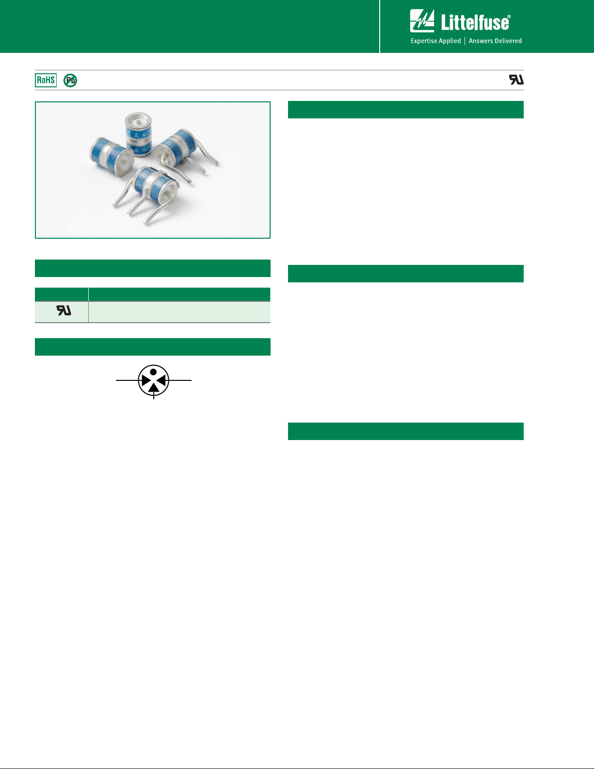
SL1003A Series
SL1003A Series
Agency Approvals
AGENCY AGENCY FILE NUMBER
®
3 Electrode GDT Graphical Symbol
E128662
Description
The SL1003A series has been especially developed
for Broadband equipment. Special design features
provide high levels of protection against fast rising
transients in the 100V/s to 1kV/s range usually
caused by lightning disturbances.
These devices have ultra low capacitance 1.5pF and
present insignificant signal losses up to 1.5GHz.
These devices are extremely robust and are able to
divert a 5000A pulse without destruction. For AC
Power Cross of long duration, over-current protection
is recommended.
Features
• RoHS compliant
• Low insertion loss
• Surface mountable
• 5kA surge capability
tested with 8/20/s
pulse as defined by IEC
61000-4-5
• GHz working frequency
• Can be used to meet
Telcordia GR1089
without series
resistance
• 10/700 6kV capability,
as per ITU-Tk.21,
enhanced test level
• 2000 Amp 2/10s surge
rating
• Excellent response to
fast rising transients
®
Applications
• Broadband equipment
• ADSL equipment
• XDSL equipment
• Satellite and CATV
equipment
• General telecom
equipment
SL1003A Series
40
Revised: November 10, 2009
Revised: November 10, 2009
Specifications are subject to change without notice.
Customer should verify actual device performance in their specific applications.
Please refer to www.littelfuse.com for current information.
©2009 Littelfuse, Inc.
Page 2
Gas Discharge Tube (GDT) Products
SL1003A Series
Electrical Characteristics
Device Specifications (at 25°C) Life Ratings
DC Breakdown
Part Number
in Volts
(@100V/s)
MIN TYP MAX MAX MIN MAX TYP TYP @ 10/350μs
SL1003A090 72 90 108
SL1003A230 184 230 276
SL1003A250 200 250 300
SL1003A260 210 260 310
SL1003A300 240 300 360 750 850
SL1003A350 280 350 420 800 900
SL1003A400 320 400 480 850 950
SL1003A450 360 450 540 900 1000
SL1003A500 400 500 600 1100 1400
Notes:
1. At delivery AQL 0.65 level II, DIN ISO 2859
2. In ionized mode, tested according to ITU-T Rec. K.12
3. Comparable to the silicon measurement Switching Voltage (Vs)
4. Reference REA PE-80, 0.2A. Tested to ITU-T Rec. K.12 and REA PE-80 < 150 msecs.
1,2,3
Impulse
Breakdown
2,3
in Volts
(@100V/µs)
600
Impulse
Breakdown
2,3
In Volts
(@1kV/µs)
700
750
Insulation
Resistance
9
10
(at 50V)
9
10
(at 100V)
Capaci-
tance
(@1MHz
0V Bias)
1.5 pF
Arc
Voltage
(on state
Voltage)
@1Amp Min
~10 to
35 V
Surge
Life
(@200A
10/1000µs)
300
shots
Nominal
Impulse
Discharge
Current
(8/20µs)
10 shots
(@10kA)
Nominal
AC
Discharge
Current
(10x1s
@50Hz)
10 A 30 A
AC
Discharge
Current
(9 Cycles @
50Hz)
DC
Holdover
Voltage
50 V
135 V
Max Impulse
Discharge
4
Current
(1 Application)
2 kA
Product Characteristics
Materials
Product Marking
Leaded Device: Nickel-plated with Tin-
plated wires
Core and Surface Mount: Dull Tin-plated
Littelfuse 'LF' Mark, voltage and date
code
Glow to Arc
Transition Current
Glow Voltage
Storage and
Operational
Temperature
~1 Amp
~60 to 200 Volts
-40 to +90°C
©2009 Littelfuse, Inc.
Specifications are subject to change without notice.
Please refer to www.littelfuse.com for current information.
Customer should verify actual device performance in their specific applications.
41
Revised: November 10, 2009
SL1003A Series
Page 3

Device Dimensions
Gas Discharge Tube (GDT) Products
SL1003A Series
For SL1003A series:
'R' Type Radial Lead Devices (SL1003AxxxR-001)
PROFILE VIEW TOP VIEW
4.3 + 1.5
[0.169 + 0.059]
6.0 ± 0.5
[0.236 ± 0.020]
4.4 ± 0.3
[0.173± 0.012]
12.2 - 2
[0.480 - 0.079]
8.1 ± 0.2
[0.319 ± 0.0079]
4.4 ± 0.3
[0.173± 0.012]
Ø6.3 ± 0.2
[0.248 ± 0.0079]
0.8 DIA. MAX.
[0.031]
'R' Type Radial Lead Devices (SL1003xxxF and SL1003xxxRF)
PROFILE VIEW TOP VIEW
12.2 - 2
[0.480 - 0.079]
8.1 ± 0.2
[0.319 ± 0.0079]
Ø6.3 ± 0.2
[0.248 ± 0.0079]
Dimensions are in millimeters [and inches]
'C' Type Core Devices
PROFILE VIEW
8.1 ± 0.2
[0.319 ± 0.0079]
'SM' Type Surface Mount Devices
TOP VIEW
6.0 ± 0.1
3.20
[0.126]
TOP VIEW
Ø6.0 ± 0.1
[0.236 ± 0.0039]
PROFILE VIEW
8.1 ± 0.2
[0.319 ± 0.0079]
4.3 + 1.5
[0.169 + 0.059]
[0.260 + 0.020]
4.3 + 1.5
[0.169 + 0.059]
6.0 ± 0.5
[0.236 ± 0.020]
[0.154± 0.012]
6.6 ± 0.5
6.0 ± 0.5
[0.236 ± 0.020]
[0.154± 0.012]
3.9 ± 0.3
3.9 ± 0.3
3.9 ± 0.3
[0.154± 0.012]
PROFILE VIEW TOP VIEW
12.2 - 2
[0.480 - 0.079]
8.1 ± 0.2
0.8 MAX.
[0.319 ± 0.0079]
3.9 ± 0.3
[0.154± 0.012]
0.8 DIA. MAX.
[0.031]
Ø6.3 ± 0.2
[0.248 ± 0.0079]
3 ± 0.5 [0.118 ± 0.020]
0.8 DIA. MAX.
[0.031]
2 ± 0.5
[0.079 ± 0.020
Ø6.8 ± 0.1
6.000
[0.236]
1.20
[0.04]
Ø6.0 ± 0.1
TOP VIEW
7.60
[0.299]
2.20
[0.087]
1.20
[0.047]
SL1003A Series
42
Revised: November 10, 2009
Specifications are subject to change without notice.
©2009 Littelfuse, Inc.
Customer should verify actual device performance in their specific applications.
Please refer to www.littelfuse.com for current information.
Page 4

Gas Discharge Tube (GDT) Products
SL1003A Series
Soldering Parameters - Reflow Soldering (Surface Mount Devices)
Reflow Condition Pb-free assembly
- Temperature Min (T
Pre Heat
- Temperature Max (T
- Time (Min to Max) (ts) 60 – 180 seconds
Average Ramp-up Rate (Liquidus Temp
(TL) to peak)
T
to TL - Ramp-up Rate 5°C/second max.
S(max)
Reflow
- Temperature (TL) (Liquidus) 217°C
- Temperature (tL) 60 – 150 seconds
Peak Temperature (TP) 260
Time within 5°C of Actual Peak
Temperature (tp)
Ramp-down Rate 6°C/second max.
Time 25°C to Peak Temperature (TP) 8 minutes max.
Do not exceed 260°C
) 150°C
s(min)
) 200°C
s(max)
3°C/second max.
+0/-5
°C
10 – 30 seconds
T
Temperature
S(max)
T
S(min)
T
P
T
L
25
time to peak temperature
Preheat
t
S
(t 25ºC to peak)
Ramp-up
t
P
Critical Zone
T
to T
L
P
t
L
Ramp-down
Time
Soldering Parameters - Wave Soldering (Thru-Hole Devices)
300
280
260
240
220
200
180
160
140
120
100
80
60
40
20
0
Temperature (°C) - Measured on bottom side of board
0
102030405060708090
Time (Seconds)
Preheat Time
100
110
120
130
140
150
160
170
180
190
200
210
220
230
Dwell Time
Cooling Time
Soldering Parameters - Hand Soldering
Solder Iron Temperature: 350° C +/- 5°C
Heating Time: 5 seconds max.
Recommended Process Parameters:
Wave Parameter Lead-Free Recommendation
Preheat:
(Depends on Flux Activation Temperature)
Temperature Minimum:
Temperature Maximum:
Preheat Time: 60-180 seconds
Solder Pot Temperature:
Solder Dwell Time: 2-5 seconds
240
(Typical Industry Recommendation)
100
° C
150
° C
280
° C Maximum
©2009 Littelfuse, Inc.
Specifications are subject to change without notice.
Please refer to www.littelfuse.com for current information.
Customer should verify actual device performance in their specific applications.
43
Revised: November 10, 2009
SL1003A Series
Page 5

Gas Discharge Tube (GDT) Products
SL1003A Series
Packaging
'C' Type Core Items: Package bulk pack in polybag, 500 pcs/bag
'R' and ‘RF’ Type Radial Lead Items: Packed in tray, 100 pcs/tray
'SM' Type Surface Mount Items: Packaged tape and reel carrier, 700 pcs/reel (specifications below)
Dimensions are in millimeters [and inches]Dimensions are in millimeters [and inches]
0.4 ± 0.05
[0.016 ± 0.0020]
x
a
m
°
0
2
8.6 ± 0.1
14 [0.551]
[0.339 ± 0.0039]
5°
m
a
x
4 [0.157]
3 [0.118]
24 ± 0.3
[ 0.945 ± 0.012]
7.4 ± 0.1
[0.291 ± 0.0039]
1.75 ± 0.1
[0.069 ± 0.0039]
11.5 ± 0.1
[0.453 ± 0.0039]
R0.3 typical
[0.012]
10x4 ± 0.1 = 40 ± 0.2
[10x0.157 ± 0.004 = 1.575 ± 0.008]
Ø1.5 +0.1
[0.059 +0.0039]
Ø4 ± 0.1
[0.157 ± 0.0039]
12 ± 0.1
[0.472 ± 0.0039]
SMD-tape according to IEC 60286-3
Ø1.5 +0.1
[0.059 +0.0039]
Ø2 ± 0.1
[0.079 ± 0.0039]
3
[0.118]
6.1 ± 0.1
[0.240 ± 0.0039]
9
[0.354]
17.7
[0.697]
275.0
[10.83]
76.0
[2.99]
100.0
[3.94]
25.0
[0.98]
Direction of Feed
Part Numbering System and Ordering Information
SL1003 A XXX XX
Type 3 Pole Arrestor
Voltage
Pin Configuration
C = Core type (Packed in polybag, 500pcs/bag)
R = Radial Lead without Failsafe (Packed in tray, 100pcs/tray)
RF = Radial Lead with Failsafe (Packed in tray, 100pcs/tray)
SM = Surface Mount (Packed in carrier and tape, 700pcs/reel)
SL1003A Series
44
Revised: November 10, 2009
Specifications are subject to change without notice.
©2009 Littelfuse, Inc.
Customer should verify actual device performance in their specific applications.
Please refer to www.littelfuse.com for current information.
 Loading...