

Littelfuse FPS User Manual
Protection Relays & Controls
Feeder Protection–Advanced
FPS SERIES
Feeder Protection System
1
Description
The FPS Feeder Protection System monitors voltage
and current to provide a comprehensive package of
17 protective functions. The FPS is a modular system
with integrated protection, breaker control, metering,
and data-logging functions.
1
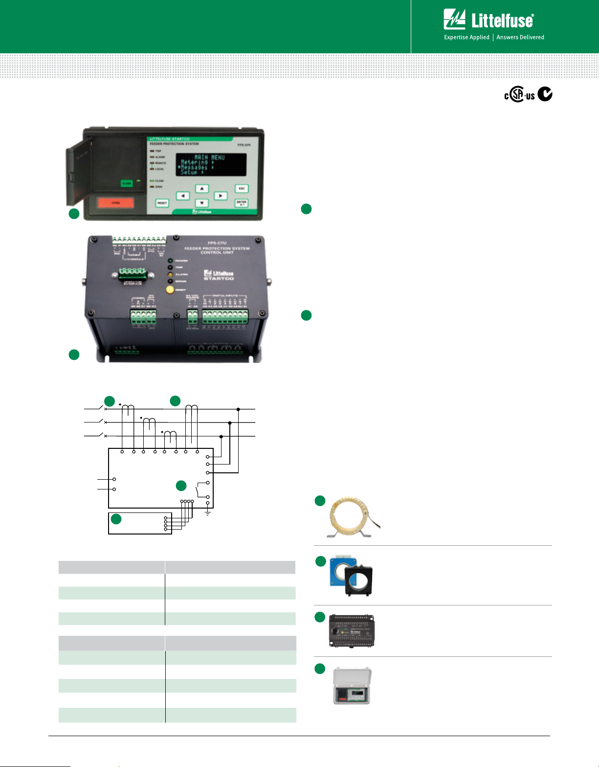
Operator Interface (FPS-OPI)
g
Large, bright, 4 x 20 vacuum-fluorescent display
g
Display metered values
g
Access set points
g
Powered by Control Unit
g
Panel mount or attach directly to Control Unit
g
Remote mounting (1.2 km or 4000 ft maximum loop length)
g
1/2 DIN size
g
Hazardous-location certified
2
Simplified Circuit Diagram
GF CTPHASE CT
A
PHASE CT
1
FPS-OPI
(Operator Interface)
FPS-CTU
(Control Unit)
L1
L2
B
PHASE CT
2
Ordering Information
ORDERING NUMBER COMMUNICATIONS
FPS-CTU-01-00 RS-485
FPS-CTU-02-00 RS-485 & DeviceNet
FPS-CTU-03-00 RS-485 & Profibus
FPS-CTU-04-00 RS-485 & Ethernet
ACCESSORIES REQUIREMENT
FPS-OPI-01-00 Recommended
SE-IP65CVR-M Optional
Phase CTs Required
Ground-Fault CT Recommended
MPS-RTD-01-00 Optional
2
Control Unit (FPS-CTU)
g
Current inputs—5-A or 1-A secondary phase
current transformers
g
Voltage inputs—up to 600 V without PTs
g
Earth-leakage input—5-A or 1-A secondary or
sensitive transformer
g
8 digital inputs, 5 relay outputs, 1 analog input and output
g
24-Vdc supply for OPI and RTD modules, and for digital inputs
g
IRIG-B time-code input
g
1/2 DIN size, surface mount
g
RS-485 network communications (Standard)
g
DeviceNet™, Profibus®, or Ethernet communications available
Accessories
A
B
™
®
C
D
Phase Current Transformers
Phase CTs are required to detect phase
currents.
Ground-Fault Current Transformer
Zero-sequence current transformer detects
ground-fault current. Available with 5-A
and 30-A primary ratings for low-level pickup.
MPS-RTD Temperature Input Module
Optional module provides 8 inputs to connect
Pt100, Ni100, Ni120, and Cu10 RTDs.
SE-IP65CVR-M Cover
Optional gasketed, transparent cover for
limited access and IP65 protection for an
Operator Interface Module.
© 2013 Littelfuse Protection Relays & Controls
Littelfuse.com/fps
Rev: 4-A-050213
Based on Manual Rev 0
Protection Relays & Controls
Feeder Protection–Advanced
FPS SERIES
Feeder Protection System
Features & Benefits
FEATURES IEEE # BENEFITS
Overload 49, 51
Inverse-time overcurrent 50, 51 Coordination using IEEE and IEC Curves
Definite-time overcurrent 50, 51 Instantaneous overcurrent to detect catastrophic failure
Current unbalance/
Phase loss/Phase reverse
46 Detects an open or high-impedance phase
Ground fault 50G/N, 51G/N Inverse and definite time. Early insulation-failure detection.
RTD temperature 38, 49 Optional protection (MPS-RTD module) for load-temperature monitoring
Overvoltage 59 Limits stress to insulation
Undervoltage 27 Detects a damaging brown-out condition
Voltage unbalance
47 Detects unhealthy supply voltage
Two setting groups
Breaker control Allows local and remote operation; reduces component count
Metering Displays the measured and calculated parameters
Data logging On-board 64-event recorder helps with system diagnosis
Communications Remotely view measured values, event records, & reset trips
Conformal coating Internal circuits are conformally coated to protect against corrosion and moisture
Long-time overcurrent provides thermal protection for feeder or load
Minimizes Arc-Flash hazards during maintenance
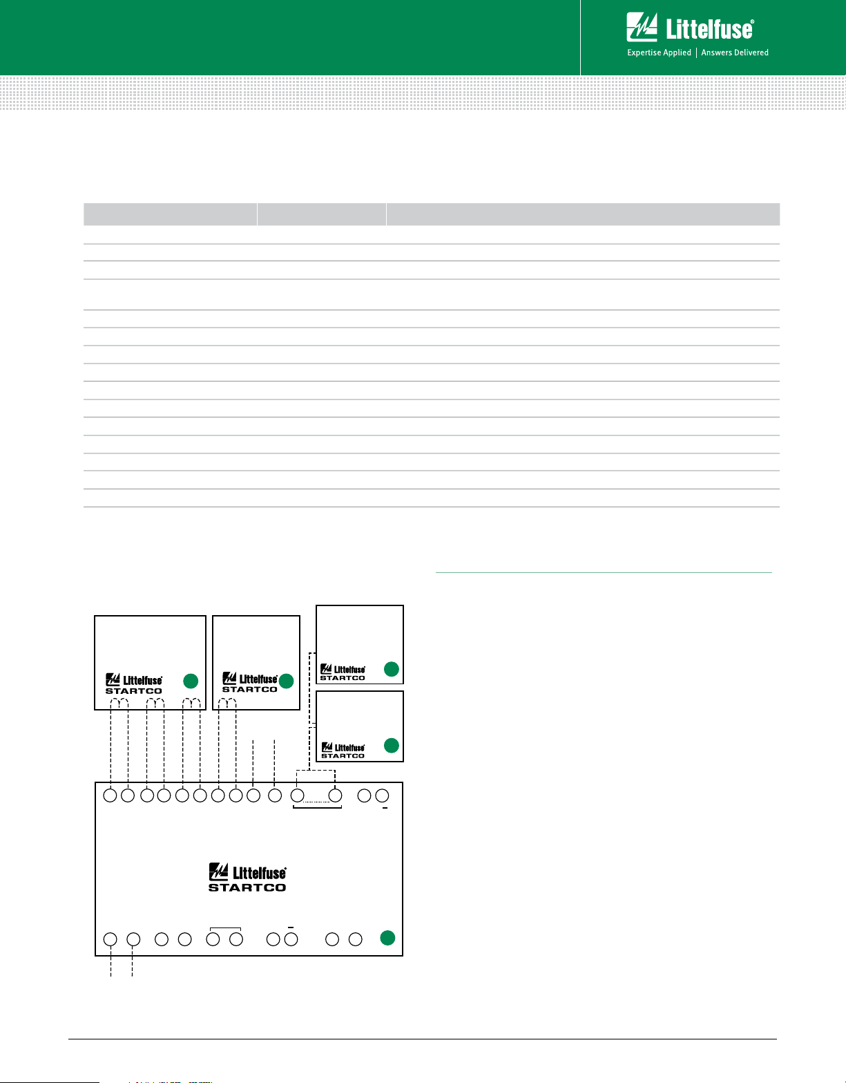
Wiring Diagram
PHASE CURRENT
TRANFORMERS
(required)
A B
33 22
30 29 27 26 23 22
RELAY
OUTPUTS
2
1
CONTROL
POWER
5 16
......
GROUND-FAULT
CURRENT
TRANSFORMER
(recommended)
PHASE
VOLTAGES
20 17
......
CONTROL UNIT
FPS-CTU
ANALOG
OUTPUT
RS-485
35 37
......
4-20 mA
+
39 40
OPERATOR INTERFACE
FPS-OPI
(recommended)
RTD MODULE
MPS-RTD
(optional)
60 56
I/0 MODULE
DIGITAL
INPUTS
43 51
Specifications
Protective Functions
(IEEE Device Numbers)
Overload (49, 51)
Phase reverse (current) (4 6)
Overfrequency (81)
Overcurrent (50, 51)
1
Underfrequency (81)
Ground fault (50G/N, 51G/N)
Unbalance (voltage) (47)
RTD temperature (38, 49)
Input Voltage 65-265 Vac, 25 VA; 80-275 Vdc, 25 W
C
Power-Up Time 800 ms at 120 Vac
Ride-Through Time 100 ms minimum
24-Vdc Source 100 mA maximum
AC Measurements True RMS and DF T, Peak, 16 samples/cycle, and
53 52
+
4-20 mA
ANALOG
INPUT
positive and negative sequence of fundamental
Frequency 50 or 60 Hz
Inputs Phase current, Earth-leakage current, Phase voltage,
7 digital, 1 analog
Output Contacts 5 contacts — See Product Manual
Approvals CSA certified, C-Tick (
Communications Allen-Bradley
®
DFI and Modbus® RTU (Standard);
DeviceNet™, Profibus
Conformal Coating Standard feature
Warranty 10 years
......
2
Mounting:
Control Unit Surface
Operator Interface Panel, Control-Unit mounted
Unbalance (current) (46)
Phase loss (voltage) (47)
Overvoltage (59)
Phase loss (current) (46)
Undervoltage (27)
Phase reverse (voltage) (47)
Power factor (55)
Australian)
®
, Ethernet (Optional)
© 2013 Littelfuse Protection Relays & Controls
Littelfuse.com/fps
Rev: 4-A-050213
Based on Manual Rev 0
 Loading...