

Page 1
Teccor® brand Protection Thyristors
Axial Leaded
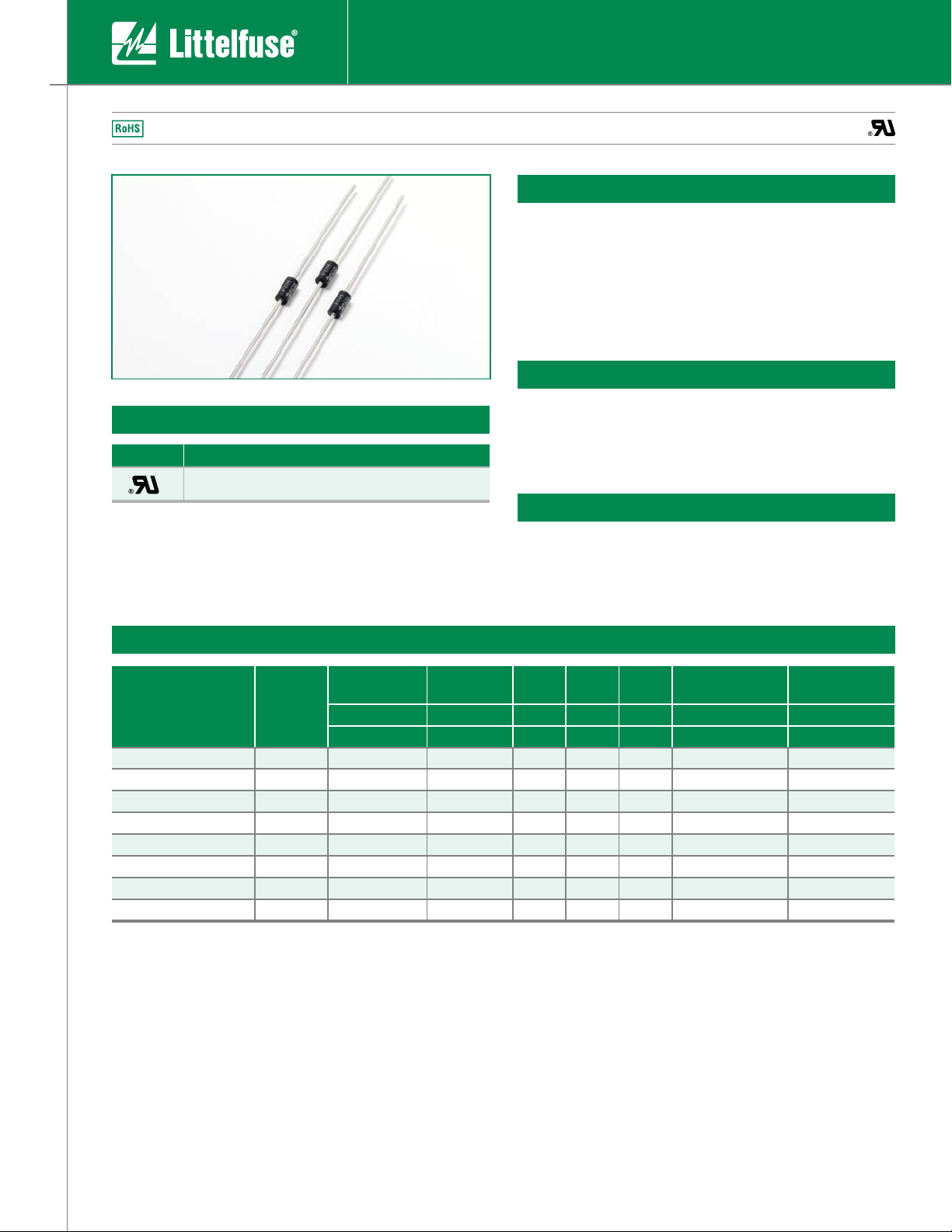
DO-41 Series SIDACtor® Device
Agency Approvals
Agency Agency File Number
E133083
Description
This DO-41 plastic package provides a through-hole version
of the SIDACtor® devices. This axial leaded device is ideal for
Customer Premises Equipment (CPE) such as telephones,
answering machines, modems, and fax interfaces. The DO-41
package series can also be used for overvoltage protection
for applications such as T1/E1/J1 trunk cards when the
appropriate overcurrent protection is included.
Features
• RoHS compliant
•
Bidirectional transient voltage protection
•
Axial lead through-hole component
•
Teccor brand SIDACtor technology
Protection solution to meet
• YD/T 950
•
YD/T 993
•
YD/T 1082
•
GR 1089 Intra-building
•
IEC 61000-4-5
•
ITU K.20/21 Basic Level
•
TIA-968-A Type B Surges
Electrical Characteristics
V
DRM
@l
=5µA
Part Number Marking
P1100THLRP P11H 90 130 150 800 1.0 5 60
P1300THLRP P13H 120 160 150 800 1.0 5 40
P1500THLRP P15H 140 180 150 800 1.0 5 40
P1800THLRP P18H 170 220 150 800 1.0 5 40
P2300THLRP P23H 190 260 150 800 1.0 5 30
P2600THLRP P26H 220 300 150 800 1.0 5 30
P3100THLRP P31H 275 350 150 800 1.0 5 30
P3500THLRP P35H 320 400 150 800 1.0 5 30
• All measurements are made at an ambient temperature of 25°C.
• Listed SIDACtor devices are bidirectional. All electrical parameters and surge ratings
apply to forward and reverse polarities.
DRM
Volts Volts mAmps mAmps Amps Volts pF
Min Max Min Max Max Max Typical
V
S
@100V/µs
V
I
H
I
S
I
T
T
@IT=1 amp
Capacitance
@1MHz, 2V bias
DO-41 Series
Specifications are subject to change without notice.
1
Telecom Design Guide
www.littelfuse.com
©2006 Littelfuse
Page 2
Teccor® brand Protection Thyristors
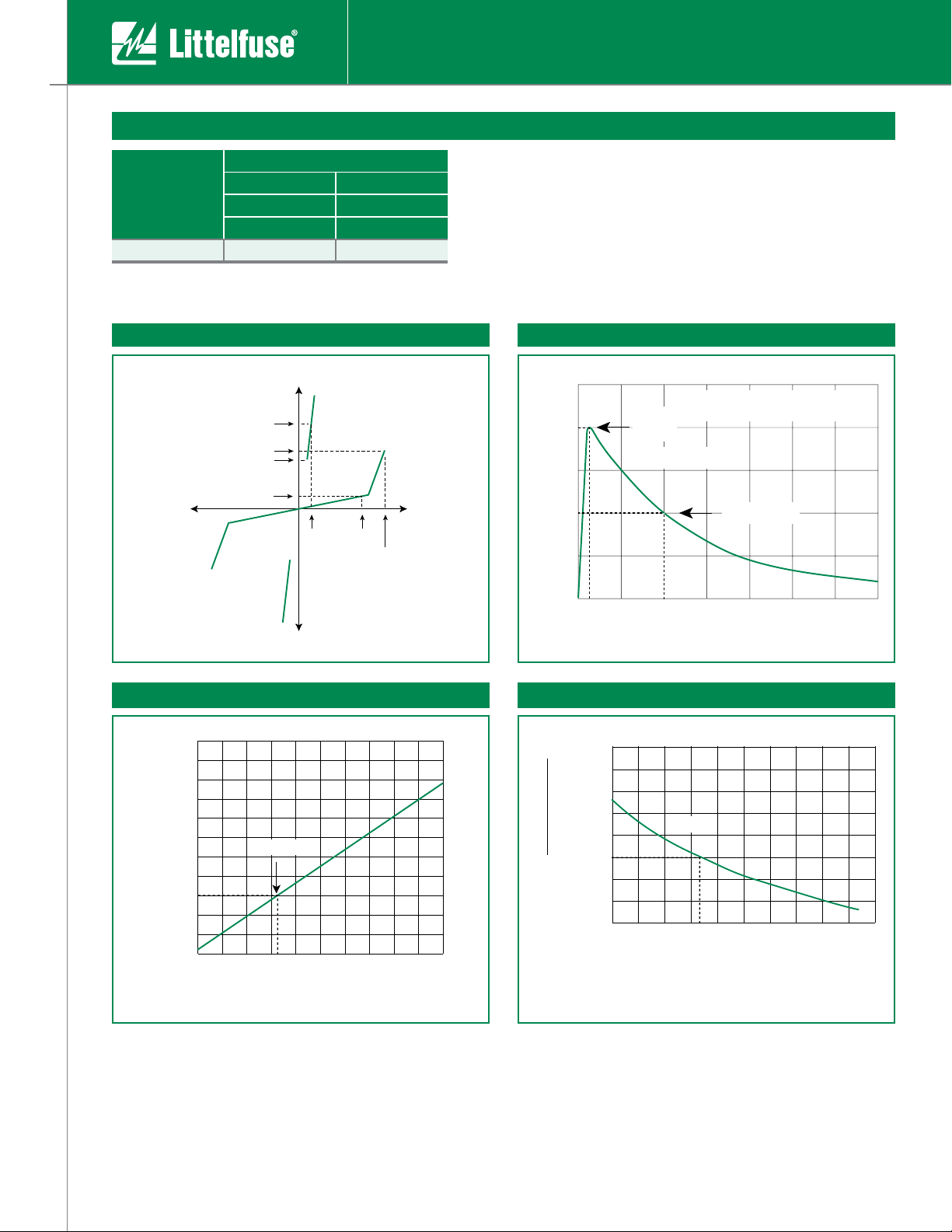
I
H
I
T
I
S
I
DRM
V
DRM
V
T
+V
-V
+I
-I
V
S
50
100
0
t
r
t
d
0
Peak
Value
Half Value
t – Time (µs)
I
PP
– Peak Pulse Current – %I
PP
tr = rise time to peak value
td = decay time to half value
Waveform = tr x td
-8
-40 -20 0 20 40 60 80 100 120 140 160
-6
-4
0
2
4
6
8
10
12
14
Junction Temperature (TJ) – ˚C
Percent of V
S
Change – %
25 ˚C
0.4
-40 -20 0 20 40 60 80 100 120 140 160
0.6
0.8
1.0
1.2
1.4
1.6
1.8
2.0
Case Temperature (TC) – ˚C
Ratio of
I
H
I
H
(T
C
= 25 ˚C)
25 ˚C
Axial Leaded
Surge Ratings
I
PP
Series
H
• I
applies to -40°C through +85°C temperature range.
PP
• I
is a repetitive surge rating and is guaranteed for the life of the product.
PP
5x320 µs 10x1000 µs
Amps Amps
Min Min
25 35
tr x td Pulse WaveformV-I Characteristics
Normalized VS Change Versus Junction Temperature Normalized DC Holding Current Versus Case Temperature
DO-41 Series
Specifications are subject to change without notice.
2
Telecom Design Guide
www.littelfuse.com
©2006 Littelfuse
Page 3

Soldering Parameters
DO-41 SERIES
MIN
1.000
[25.40]
[25.40]
1.000
MIN
Dimensions in inches and (millimeters)
[2.00]
.080
.107
(2.72)
[5.21]
.205
.160
[4.10]
[0.71]
.028
.034
[0.86]
Teccor® brand Protection Thyristors
Axial Leaded
Reflow Condition
Pre Heat
- Temperature Min (T
- Temperature Max (T
s(min)
s(max)
)
- Time (min to max) (ts)
Average ramp up rate (Liquidus Temp
(TL) to peak)
T
to TL - Ramp-up Rate
S(max)
Reflow
- Temperature (TL) (Liquidus)
- Time (min to max) (ts)
Peak Temperature (TP)
Time within 5°C of actual peak
Temperature (tp)
Ramp-down Rate
Time 25°C to peak Temperature (TP)
Do not exceed
Physical Specifications
Terminal Material
Lead Solderability
Matte Tin-plated Axial leads
MIL-STD-750, Method 2026
Pb – Free assembly
150°C
190°C
)
50 – 150 seconds
5°C/second max
5°C/second max
220°C
>60 – <150 seconds
+0/-5
250
20 – 40 seconds
5°C/second max
8 minutes max.
280°C
°C
Environmental Specifications
Operating/Storage
Temperature
Passive Aging
-40° C to ~ +150°C
125° C, 1000 hours
Meet Spec
Dimensions
Humidity Aging
Thermal Shock
Solvent Resistance
Vibration
+85°C, 85% R.H. 1000 hours
Meet Spec
MIL-STD-202 Method 107G
+85°C/-40°C 100 times
Meet Spec
MIL-STD-202, Method 215
No Change
MIL-STD-883C, Method 2007.1,
Condition A
No Change
DO-41 Series
Specifications are subject to change without notice.
3
Telecom Design Guide
www.littelfuse.com
©2006 Littelfuse
Page 4

Teccor® brand Protection Thyristors
CONSTRUCTION VARIATION
0
P
: Single SIDACtor chip used
as a single device
PACKING STYLE
RP
: Reel Pack per EIA RS-296
SURGE IPP Rating
H
: 35A 10/1000µs
PACKAGE TYPE
T
: DO-41
L
:
RoHS Compliant
DEVICE TYPE
: SIDACtor
Pxxx0 T H L RP
MEDIAN VOLTAGE
xxx
: xxx volts
First Line: Product Name (see marking column in
table on page 1)
Second Line: Lot number
XXXX
XXXX
OFF CENTER BOTH SIDES
(±0.039")
B
OVERALL
LENGTH
C
A
H
D
OFF CENTER BOTH SIDES
(±0.039")
B
OVERALL
LENGTH
C
A
E
F
G
H
LABEL
recess depth max 0.75”
D
Axial Leaded
Part Marking System Part Numbering System
Packaging
Package
Type
Description
Packing
Quantity
DO-41 Axial 5000
Tape and Reel Specification
Symbol Case Type Inches MM
Component Spacing
A
(lead to lead)
B Tape Spacing 2.062 ± 0.059” 52.37 ± 1.498
C Tape Width 0.250” 6.35
D Max. Off Alignment 0.048” 1.219
E Reel Dimension 13” 330.2
F Max Hub Recess 3” 76.19
G Max. Abor Hole 0.68” 17.27
H Reel Dimension 2.75” 69.85
0.200 ± 0.020” 5.08 ± 0.508
Added
Suffix
RP
Industry
Standard
EIA RS-296
DO-41 Series
Specifications are subject to change without notice.
4
Telecom Design Guide
www.littelfuse.com
©2006 Littelfuse
 Loading...