

Page 1

Varistor Products
Industrial High Energy Terminal Varistors > DHB34 Series
DHB34 Varistor Series
Agency Approvals
Agency Agency File Number
1449, E320116, 1414, E56529
LR91788
RoHS
Description
The DHB34 Series of transient surge suppressors is
comprised of two industrial high-energy Metal-Oxide
Varistors (MOVs) discs placed in parallel as a single device.
They are designed to provide surge suppression in the
AC mains outdoor and service entrance environment
(distribution panels) of buildings. DHB34 applications
also include industrial heavy motors, controls, and power
supplies such as used in the oil-drilling, mining, and
transportation fields, including HVAC and motor/generator
applications.
The DHB34 Series provides rigid terminals for throughhole solder mounting on printed circuit boards, thereby
eliminating the need for screw mounting.
Features
• Lead-Free, HalogenFree and RoHS
Compliant
• Wide operating
voltage range
M(AC)RMS
110V to 750V
V
• High–energy
absorption
capability
W
= 220J to 1050J
TM
• Rigid terminals for
secure through-hole
solder mounting
• No derating up to
85ºC ambient
• Dual Disc Device two 34mm varistor
discs in parallel in
a single package.
• High peak pulse
current (Each of
two discs placed in
parallel) capability
I
= 40,000A
TM
Absolute Maximum Ratings
• For ratings of individual members of a series, see Device Ratings and Specifications chart
Continuous DHB34 Series Units
Steady State Applied Voltage:
AC Voltage Range (V
DC Voltage Range (V
Transients:
Peak Pulse Current (ITM)
For 8/20μs Current Wave (See Figure 2) 40000 A
Single Pulse Energy Range
For 2ms Current Wave (W
Operating Ambient Temperature Range (T
Storage Temperature Range (T
Temperature Coefficient (a
Hi-Pot Encapsulation (COATING Isolation Voltage Capability) 2500 V
COATING Insulation Resistance 1000 MΩ
CAUTION: Stresses above those listed in "Absolute Maximum Ratings" may cause permanent damage to the device. This is a stress only rating and operation
of the device at these or any other conditions above those indicated in the operational sections of this specification is not implied.
© 2013 Littelfuse, Inc.
Specifications are subject to change without notice.
Please refer to www.littelfuse.com/series/dhb34.html for current information.
) -55 to + 125 ºC
STG
V
) of Clamping Voltage (VC) at Specified Test Current <0.01 %/ºC
) 110 to 750 V
M(AC)RMS
) 148 to 970 V
M(DC)
) 220 to 1050 J
TM
) -55 to + 85 ºC
A
175
Revised: May 8, 2013
DHB34 Varistor Series
MOV’S
DHB34 Series
HI–ENERGY
Page 2
Varistor Products
Industrial High Energy Terminal Varistors > DHB34 Series
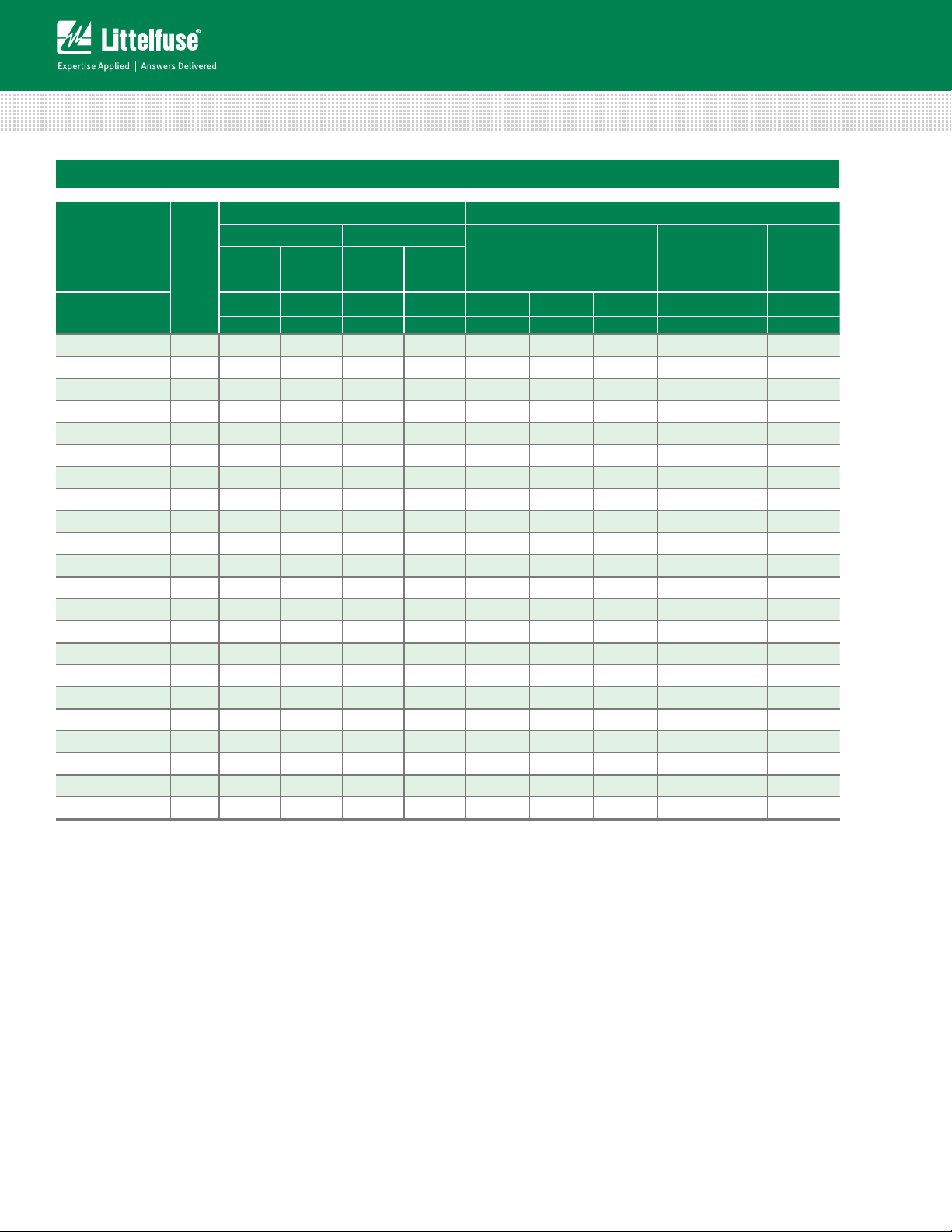
DHB34 Series Ratings & Specifications
Maximum Rating (85°C) Specifications (25°C)
Lead–free
and RoHS
Compliant Models
Model
Size
Disc
Dia.
(mm)
Part Number
V111DHB34 34 110 148 220 40,000
V131DHB34 34 130 175 270 40,000
V141DHB34 34 140 188 291 40,000
V151DHB34 34 150 200 300 40,000
V181DHB34 34 180 240 330 40,000 254 282 310 468 6,800
V201DHB34 34 200 265 350 40,000 283 314 345 533 6,350
V251DHB34 34 250 330 370 40,000 354 390 429 650 5,000
V271DHB34 34 275 369 400 40,000 389 430 473 730 4,500
V301DHB34 34 300 410 430 40,000 433 478 526 780 4,100
V321DHB34 34 320 420 460 40,000 462 510 561 830 3,800
V331DHB34 34 330 435 475 40,000 467 519 570 843 3,750
V351DHB34 34 350 460 500 40,000 495 550 604 894 3,600
V391DHB34 34 385 510 550 40,000 545 604 663 1,000 3,500
V421DHB34 34 420 560 600 40,000 610 680 748 1,130 3,000
V441DHB34 34 440 585 630 40,000 622 691 759 1,147 2,900
V481DHB34 34 480 640 650 40,000 670 750 825 1,240 2,700
V511DHB34 34 510 675 700 40,000 735 820 910 1,350 2,500
V551DHB34 34 550 710 755 40,000 778 864 949 1,404 2,390
V571DHB34 34 575 730 770 40,000 805 910 1000 1,480 2,200
V661DHB34 34 660 850 900 40,000 940 1050 1160 1,720 2,000
V681DHB34 34 680 875 925 40,000 962 1068 1173 1,777 1,900
V751DHB34 34 750 970 1050 40,000 1080 1200 1320 2,000 1,800
Continuous Transient
V
RMS
V
M(AC)
V
V
M(DC)
Energy
DC
(2ms)
WTM ITM Min V
Peak
Current
8 x 20μs
Varistor Voltage at 1mA
DC Test Current
N(DC)
Max VC f = 1MHz
Maximum
Clamping Voltage
at 200A
V
C
Current (8/20μs)
(V) (V) (J) (A) (V) (V) (V) (V) (pF)
1
156 173 190 288 11,600
2
184 200 228 345 10,000
3
198 220 248 375 9,000
4
212 240 268 405 8,000
Typical
Capaci-
tance
Note:
1. 40kA capability depends on applications rated up to 97V
2. 40kA capability depends on applications rated up to 115V
3. 40kA capability depends on applications rated up to 123V
4. 40kA capability depends on applications rated up to 132V
DHB34 Varistor Series
. 30kA applies if > 97 V
RMS
. 30kA applies if > 115 V
RMS
. 30kA applies if > 123 V
RMS
. 30kA applies if > 132 V
RMS
.
RMS
.
RMS
.
RMS
.
RMS
176
Revised: May 8, 2013
Please refer to www.littelfuse.com/series/dhb34.html for current information.
Specifications are subject to change without notice.
© 2013 Littelfuse, Inc.
Page 3

Varistor Products
Industrial High Energy Terminal Varistors > DHB34 Series
Power Dissipation Ratings
Figure 1
Should transients occur in rapid succession, the average
power 100 dissipation result is simply the energy
(watt-seconds) per pulse times the number of pulses
per second. The power so developed must be within
the specifications shown on the Device Ratings and
Specifications table for the specific device. The operating
values must be derated as shown in above.
Peak Pulse Current Test Waveform
100
90
50
PERCENT OF PEAK VALUE
10
O
1
Figure 2
01 = Virtual Origin of Wave
T = Time from 10% to 90% of Peak
T1 = Rise Time = 1.25 x T
T2 = Decay Time
Example - For an 8/20 μs Current Waveform:
8μs = T1 = Rise Time
20μs = T2 = Decay Time
T
T
1
T
2
TIME
Maximum Clamping Voltage
10000
Maximum Clamping Voltage
DHB34 Series
Voltage VOLTS
Figure 3
110 to 750V AC Rating
V571
V551
V511
1000
V481
V441
V421
100
0.001 0.01 0.1 1 10 100 10000 100000
Current - AMPS
V391 V351 V331V321 V271 V251 V201 V181
TA = -55 C to 85C
V681V661
V301
V751
Repetitive Surge Capability
50,000
20,000
10,000
V111
V131
V141
V151
1000
SURGE CURRENT (A)
Figure 4
NOTE: If pulse ratings are exceeded, a shift of V
+/-10% could result. This type of shift, which normally results in a decrease of V
result in the device not meeting the original published specifications, but it does not
prevent the device from continuing to function, and to provide ample protection.
1
2
10
5,000
2
10
2,000
3
10
1,000
4
10
500
200
100
50
INDEFINITE
20
10
20 100 1,000 10,000
IMPULSE DURATION (μs)
DISC SIZE 34mm
V131DHB34 - V751DHB34
5
10
6
10
(at specified current) of more than
N(DC)
N(DC)
MOV’S
DHB34 Series
HI–ENERGY
, may
© 2013 Littelfuse, Inc.
Specifications are subject to change without notice.
Please refer to www.littelfuse.com/series/dhb34.html for current information.
177
Revised: May 8, 2013
DHB34 Varistor Series
Page 4
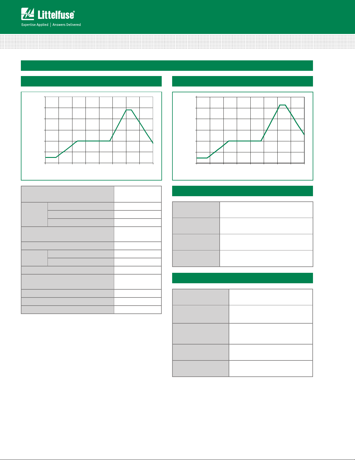
Soldering Parameters
TEMPERATURE
(
C)
TEMPERATURE
(ºC)
Varistor Products
Industrial High Energy Terminal Varistors > DHB34 Series
Non Lead–free Profile
300
250
º
200
150
100
50
0
00.5 11.5 22.5 33.5 4
Figure 5
Reflow Condition Pb – Free assembly
- Temperature Min (Ts(min)) 150°C
Pre Heat
- Temperature Max (Ts(max)) 200°C
- Time (min to max) (ts) 60 – 180 secs
Average ramp up–rate (Liquidus Temp (TL)
to peak
TS(max) to TL - Ramp-up Rate 5°C/second max
Reflow
- Temperature (TL) (Liquidus) 217°C
- Temperature (tL) 60 – 150 seconds
Peak Temperature (TP) 250
Time within 5°C of actual peak
Temperature (tp)
Ramp-down Rate 5°C/second max
Time 25°C to peak Temperature (TP) 8 minutes Max.
Do not exceed 260°C
Maximum Wave 240C
TIME(MINUTE
S)
5°C/second max
+0/-5
20 – 40 seconds
°C
Lead–free Profile
300
250
200
150
100
50
Figure 6
0
00.5 11.522.533.54
Maximum Wave 260C
TIME(MINUTES)
Physical Specifications
Lead Material Tin–coated Copper
Soldering
Characteristics
Insulating Material
Device Labeling
Solderability per MIL–STD–202,
Method 208E
Cured, flame retardant epoxy polymer
meets UL94V–0 requirements.
Marked with LF, voltage, amperage rating,
and date code.
Environmental Specifications
Operating/Storage
Temperature
Humidity Aging
-55°C to +85°C/-55°C to +125°C
+85°C, 85% RH, 1000 hours
+/-10% Voltage change
DHB34 Varistor Series
Thermal Shock
Solvent Resistance MIL–STD–202, Method 215F
Moisture Sensitivity Level 1, J–STD–020C
178
Revised: May 8, 2013
+85°C to -40°C 5 times
+/-10% Voltage change
Please refer to www.littelfuse.com/series/dhb34.html for current information.
Specifications are subject to change without notice.
© 2013 Littelfuse, Inc.
Page 5

Varistor Products
Industrial High Energy Terminal Varistors > DHB34 Series
Dimensions (mm)
37.5 max
56 max
12.7 typ
3.7 typ
B
A
Dia 3.81 +/- 0.08
Configuration
C
MOV1 MOV2
25.4 +/- 0.5
0.51 typ
7.06 +/- 0.2
NOTES:
- Terminals Configuration:
Terminals A & B are connected to one varistor element.
Terminals B & C connected to second varistor element.
- Dimensions:
Measures are in mm is typical, unless other wise specified.
T max
S1
Terminals
Table of Dimensions - Thickness and Terminal Offsets
Part Type T Max
S1 +/- 1.15
mm
V111DHB34 7.6 2.65 5.50
V131DHB34 7.8 2.85 5.70
V141DHB34 8.2 3.00 6.00
V151DHB34 8.8 3.15 6.30
V181DHB34 9.0 3.25 6.50
V201DHB34 9.2 3.35 6.70
V251DHB34 9.10 3.00 6.00
V271DHB34 9.55 3.25 6.50
S2
V301DHB34 10.20 3.50 7.00
V321DHB34 10.60 3.66 7.24
V331DHB34 10.65 3.70 7.40
V351DHB34 10.5 4.10 8.20
V391DHB34 11.2 4.45 8.90
V421DHB34 12.65 4.50 9.00
V441DHB34 12.80 4.55 9.10
V481DHB34 13.55 4.80 9.60
V511DHB34 13.4 5.25 10.50
V551DHB34 14.6 5.70 11.40
V571DHB34 14.8 5.80 11.60
V661DHB34 17.20 6.65 13.30
V681DHB34 17.5 7.00 14.00
V751DHB34 18.20 7.35 14.70
S2 +/-
2.30mm
Part Numbering System
V 13 1DHB 34
VARISTOR DESIGNATOR
MAX AC
(FIRST SIGNIFICANT DIGITS) V
© 2013 Littelfuse, Inc.
Specifications are subject to change without notice.
Please refer to www.littelfuse.com/series/dhb34.html for current information.
WORKING VOLTAGE
RMS
M(AC)
V
VOLTAGE DECADE MULTIPLIER
M(AC)
DISC SIZE (mm)
SERIES DESIGNATOR
179
Revised: May 8, 2013
MOV’S
DHB34 Series
HI–ENERGY
DHB34 Varistor Series
 Loading...