

Page 1
Varistor Products
Radial Lead Varistors > C-III series
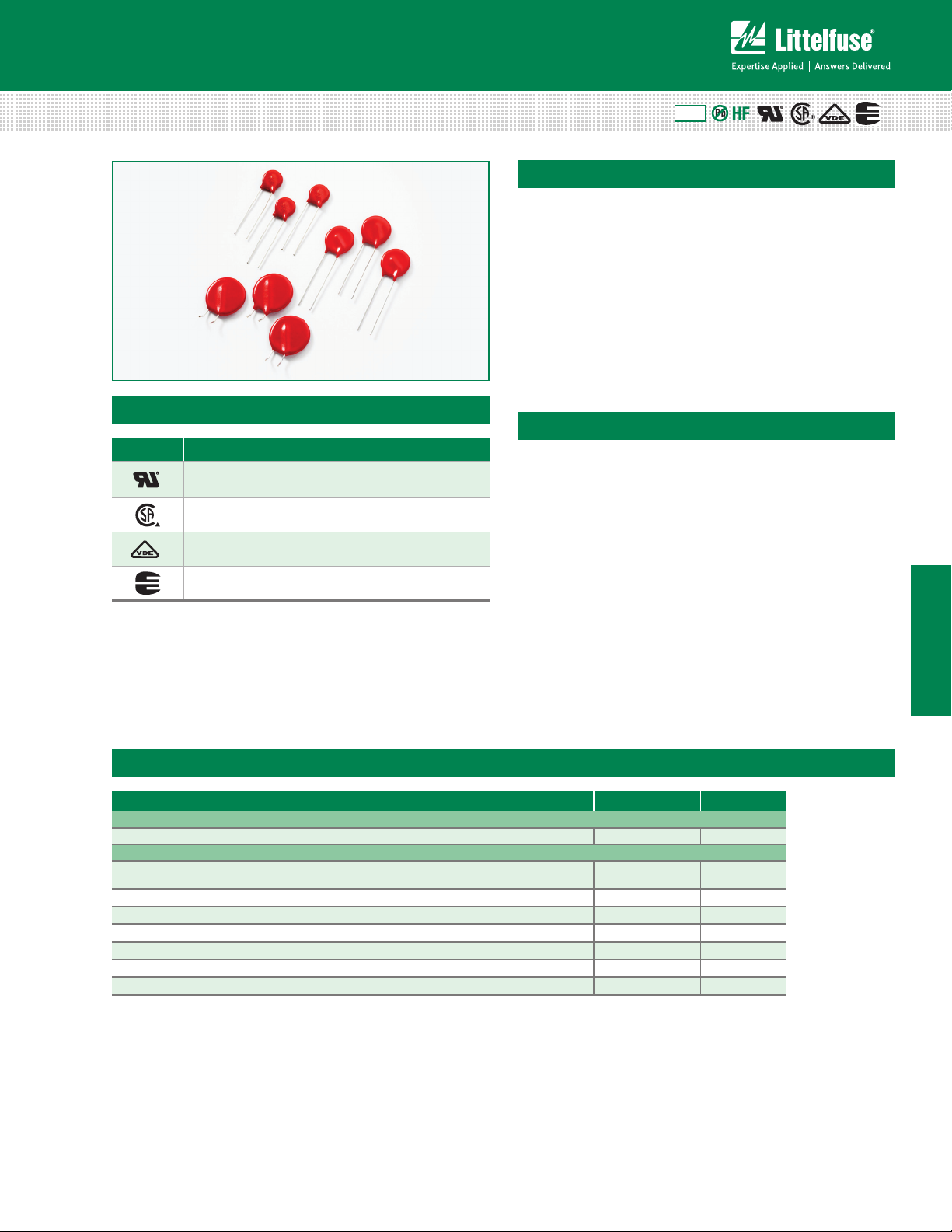
C-III Varistor Series
Agency Approvals
Agency Agency File Number
E320116
LR91788
116895
42201-006
RoHS
Description
The C-III Series of Metal-Oxide Varistors (MOVs) are
specifically designed for applications requiring high surge
energy absorption ratings and superior multiple pulse
absorption rating. This is achieved through a special
dielectric material formulation which also results in
higher repetitive surge ratings than other MOV types.
The C-III Series is primarily intended for use in AC
line Transient Voltage Surge Suppressor (TVSS)
product environment and other similar applications
requiring high transient energy and peak current
capability in a relatively small package size.
Features
• Lead–free, HalogenFree and RoHS
compliant
• High energy
absorption capability
W
40J to 530J (2ms)
TM
• High pulse life rating
• High peak pulse
current capability
I
3500A to
TM
10,000A (8/20μs)
• Available in tape and
reel for automatic
insertion; Also available
with crimped and/or
trimmed lead styles
• No derating up to
85ºC ambient
• The C-III Seriesis
supplied in 10mm,
14mm and 20mm
disc versions with
various lead options
• Wide operating
voltage range
V
M(AC)RMS
130V to 1000V
C–III Series
Absolute Maximum Ratings
• For ratings of individual members of a series, see Device Ratings and Specifications chart
Continuous C-III Series Units
Steady State Applied Voltage:
AC Voltage Range (V
Transients:
Single-Pulse Peak Current (ITM) 8/20μs Wave
(See Peak Pulse Current Test Waveform)
Single-Pulse Energy Range (W
Operating Ambient Temperature Range (T
Storage Temperature Range (T
Temperature Coefficient (a
Hi-Pot Encapsulation (COATING Isolation Voltage Capability) 2500 V
COATING Insulation Resistance 1000 MΩ
CAUTION: Stresses above those listed in "Absolute Maximum Ratings" may cause permanent damage to the device. This is a stress only
rating and operation of the device at these or any other conditions above those indicated in the operational sections of this specification is
not implied.
© 2013 Littelfuse, Inc.
Specifications are subject to change without notice.
Please refer to www.littelfuse.com/series/c-iii.html for current information.
) 2ms Rectangular Wave 40 to 530 J
TM
) -55 to +125 ºC
STG
V
) of Clamping Voltage (VC) at Specified Test Current <0.01 %/ºC
) 130 to 1000 V
M(AC)RMS
3500 to 10,000 A
) -55 to +85 ºC
A
113
Revised: June 5, 2013
C-III Varistor Series
Page 2
Varistor Products
Radial Lead Varistors > C-III series
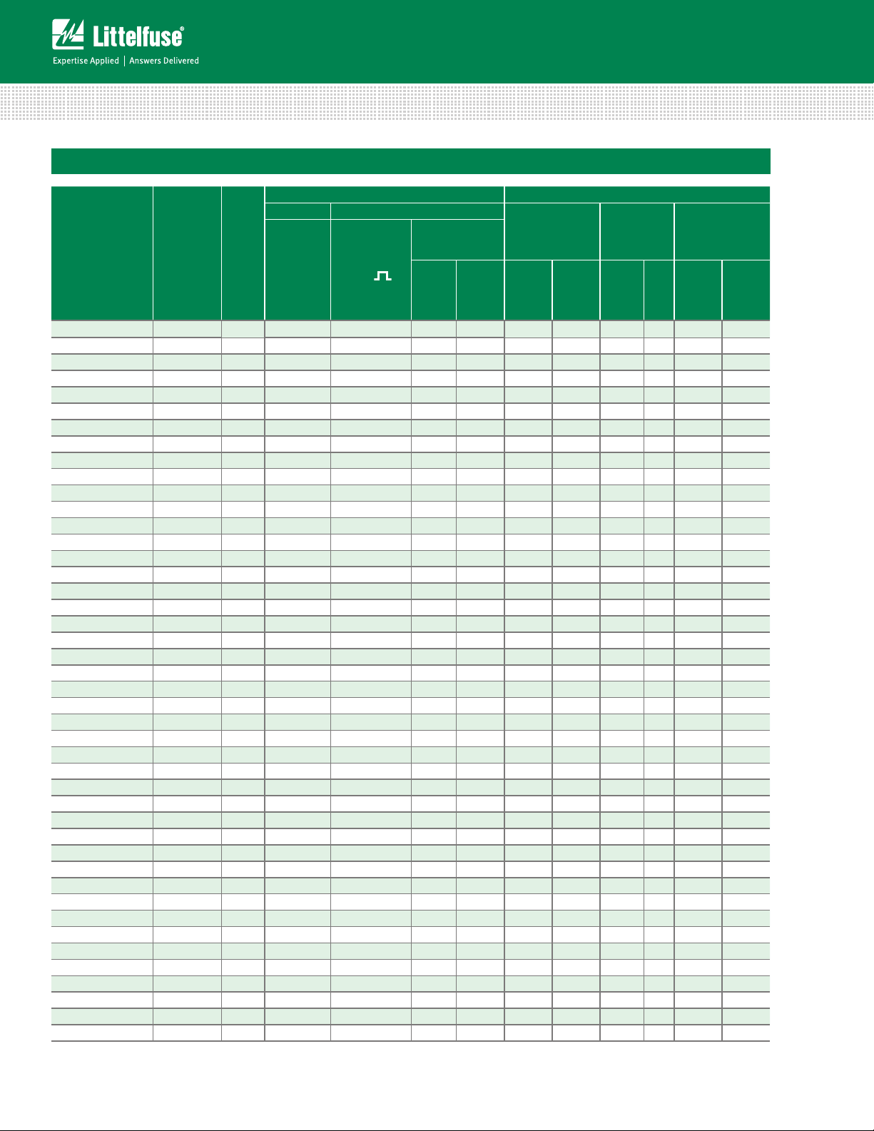
C-III Series Ratings
Maximum Ratings (85 °C) Specifications (25 °C)
Part Number Branding
Continuous Transient
Disc
Size
(mm)
Maximum
V
V
RMS
M(AC)
Withstanding
Energy (2ms)
W
(V)
TM
( )
(J)
Peak Current
(8/20μs)
I
TM1
1 Pulse
2 Pulses
(A)
I
TM2
(A)
Varistor Voltage
at 1mA DC Test
Current
V
N
Min
Max
(V)
V130LA5CP P130L5C 10 130 40 3500 3000 184 228 340 25 2 20
V130LA10CP P130L10C 14 130 80 6500 5000 184 228 340 50 10 80
V130LA20CP P130L20C 20 130 200 10000 7000 184 228 340 100 20 120
V130LA20CPX325 P130X325 20 130 200 10000 7000 184 220 325 100 20 120
V140LA5CP P140L5C 10 140 45 3500 3000 198 242 360 25 2 20
V140LA10CP P140L10C 14 140 90 6500 5000 198 242 360 50 10 80
V140LA20CP P140L20C 20 140 210 10000 7000 198 242 360 100 20 120
V140LA20CPX340 P140X340 20 140 210 10000 7000 198 230 340 100 20 120
V150LA5CP P150L5C 10 150 50 3500 3000 212 268 395 25 2 20
V150LA10CP P150L10C 14 150 100 6500 5000 212 268 395 50 10 80
V150LA20CP P150L20C 20 150 215 10000 7000 212 268 395 100 20 120
V150LA20CPX360 P150X360 20 150 215 10000 7000 212 243 360 100 20 120
V175LA5CP P175L5C 10 175 55 3500 3000 247 303 455 25 2 20
V175LA10CP P175L10C 14 175 110 6500 5000 247 303 455 50 10 80
V175LA20CP P175L20C 20 175 220 10000 7000 247 303 455 100 20 120
V175LA20CPX425 P175X425 20 175 220 10000 7000 247 285 425 100 20 120
V230LA10CP P230L10C 10 230 60 3500 3000 324 396 595 25 2 20
V230LA20CP P230L20C 14 230 125 6500 5000 324 396 595 50 10 80
V230LA40CP P230L40C 20 230 280 10000 7000 324 396 595 100 20 120
V230LA40CPX570 P230X570 20 230 280 10000 7000 324 384 570 100 20 120
V250LA10CP P250L10C 10 250 65 3500 3000 354 429 650 25 2 20
V250LA20CP P250L20C 14 250 135 6500 5000 354 429 650 50 10 80
V250LA40CP P250L40C 20 250 300 10000 7000 354 429 650 100 20 120
V250LA40CPX620 P250X620 20 250 300 10000 7000 354 413 620 100 20 120
V275LA10CP P275L10C 10 275 70 3500 3000 389 473 710 25 2 20
V275LA20CP P275L20C 14 275 145 6500 5000 389 473 710 50 10 80
V275LA40CP P275L40C 20 275 320 10000 7000 389 473 710 100 20 120
V275LA40CPX680 P275X680 20 275 320 10000 7000 389 453 680 100 20 120
V300LA10CP P300L10C 10 300 75 3500 3000 420 517 775 25 2 20
V300LA20CP P300L20C
14
300 155 6500 5000
420 517 775 50 10 80
V300LA40CP P300L40C 20 300 335 10000 7000 420 517 775 100 20 120
V300LA40CPX745 P300X745 20 300 335 10000 7000 420 490 745 100 20 120
V320LA10CP P320L10C 10 320 80 3500 3000 462 565 850 25 2 20
V320LA20CP P320L20C 14 320 165 6500 5000 462 565 850 50 10 80
V320LA40CP P320L40C 20 320 345 10000 7000 462 565 850 100 20 120
V320LA40CPX810 P320X810 20 320 345 10000 7000 462 540 810 100 20 120
V385LA10CP P385L10C 10 385 85 3500 3000 558 682 1025 25 2 20
V385LA20CP P385L20C 14 385 175 6500 5000 558 682 1025 50 10 80
V385LA40CP P385L40C 20 385 370 10000 7000 558 682 1025 100 20 120
V420LA10CP P420L10C 10 420 90 3500 3000 610 748 1120 25 2 20
V420LA20CP P420L20C 14 420 185 6500 5000 610 748 1120 50 10 80
V420LA40CP P420L40C 20 420 390 10000 7000 610 748 1120 100 20 120
V460LA10CP P460L10C 10 460 95 3500 3000 640 790 1190 25 2 20
V460LA20CP P460L20C 14 460 190 6500 5000 640 790 1190 50 10 80
VN
(V)
Maximum
Clamping
Voltage
(8/20μs)
V
I
C
(V)
(A)
Surge Rating
3kA
(8/20μs)
p
Pulses
Duty Cycle
750A
(8/20μs)
#
Pulses
#
C-III Varistor Series
114
Revised: June 5, 2013
Please refer to www.littelfuse.com/series/c-iii.html for current information.
Specifications are subject to change without notice.
© 2013 Littelfuse, Inc.
Page 3
Varistor Products
Radial Lead Varistors > C-III series
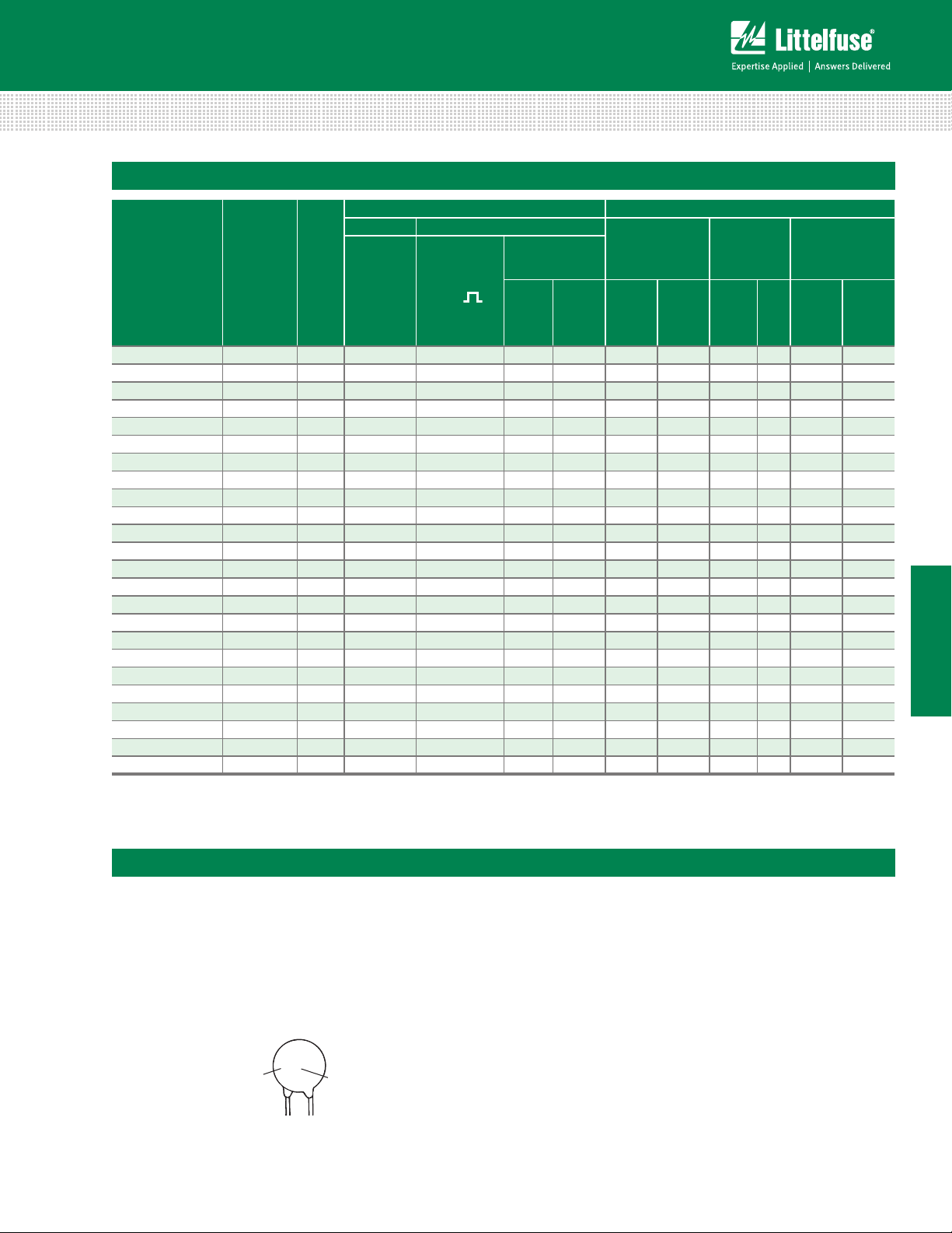
C-III Series Specifications (continued from previous page)
Maximum Ratings (85 °C) Specifications (25 °C)
Part Number Branding
Continuous Transient
Disc
Size
(mm)
Maximum
V
V
RMS
M(AC)
Withstanding
Energy (2ms)
W
(V)
TM
(J)
( )
Peak Current
(8/20μs)
I
TM1
1 Pulse
2 Pulses
(A)
Varistor Voltage
I
TM2
(A)
at 1mA DC Test
Current
V
N
Min
Max
(V)
V460LA40CP P460L40C 20 460 430 10000 7000 640 790 1190 100 20 120
V480LA10CP P480L10C 10 480 95 3500 3000 670 825 1240 25 2 20
V480LA40CP P480L40C 14 480 195 6500 5000 670 825 1240 50 10 80
V480LA80CP P480L80C 20 480 420 10000 7000 670 825 1240 100 20 120
V510LA10CP P510L10C 10 510 98 3500 3000 735 910 1350 25 2 20
V510LA40CP P510L40C 14 510 205 6500 5000 735 910 1350 50 10 80
V510LA80CP P510L80C 20 510 440 10000 7000 735 910 1350 100 20 120
V550LA10CP P550L10C 10 550 98 3500 300 780 970 1435 25 2 20
V550LA40CP P550L40C 14 550 210 6500 5000 780 970 1435 50 10 80
V550LA80CP P550L80C 20 550 450 10000 7000 780 970 1435 100 20 120
V575LA10CP P575L10C 10 575 100 3500 3000 815 1000 1500 25 2 20
V575LA40CP P575L40C 14 575 230 6500 5000 815 1000 1500 50 10 80
V575LA80CP P575L80C 20 575 460 10000 7000 815 1000 1500 100 20 120
V625LA10CP P625L10C 10 625 105 3500 3000 900 1100 1650 25 2 20
V625LA40CP P625L40C 14 625 235 6500 5000 900 1100 1650 50 10 80
V625LA80CP P625L80C 20 625 490 10000 7000 900 1100 1725 100 20 120
V660LA10CP P660L10C 10 660 110 3500 3000 940 1210 1820 25 2 20
V660LA50CP P660L50C 14 660 240 6500 5000 940 1210 1820 50 10 80
V660LA80CP P660L80C 20 660 510 10000 7000 940 1210 1820 100 20 120
V680LA10CP P680L10C 10 680 115 3500 3000 990 1240 1860 25 2 20
V680LA80CP P680L80C 14 680 240 6500 5000 990 1210 1820 50 10 80
V680LA100CP P680L100C 20 680 520 10000 7000 990 1130 1700 100 20 120
V1000LA80CP P1000L8C 14 1000 260 6500 5000 1500 1800 2700 50 10 80
V1000LA160CP P1000L16C 20 1000 530 10000 7000 1500 1800 2700 100 20 120
NOTES:
- Average power dissipation of transients not to exceed 0.6W and 1W for model sizes 14mm and 20mm, respectively.
- 7mm parts also available-contact factory for further information
- For additional or intermediar y voltage ratings contact factory
VN
(V)
Maximum
Clamping
Voltage
(8/20μs)
V
I
C
(V)
(A)
Surge Rating
3kA
(8/20μs)
p
Pulses
Duty Cycle
750A
(8/20μs)
#
Pulses
#
C–III Series
Phenolic Coating Option -- C-III Series Varistors for Hi-Temperature Operating Conditions:
• Phenolic Coated CIII Series devices are available with improved maximum operating maximum temperature 125ºC
• These devices also have improved temperature cycling performance capability.
• Ratings and Specifications are as per standard CIII Series except Hi–Pot
Encapsulation (Isolation Voltage Capability)=500V.
• To order: add X1347 to part number (e.g. V230LA40CPX1347)
• These devices are not UL, CSA, VDE or CECC certified.
• Contact factory for further details.
• Product marking:
LF 9
Lead-Free,
Halogen-Free
& RoHS Compliant
Indicator
© 2013 Littelfuse, Inc.
Specifications are subject to change without notice.
Please refer to www.littelfuse.com/series/c-iii.html for current information.
P230P40C
YYWW
Phenolic Coated
Option
Identifier
115
Revised: June 5, 2013
C-III Varistor Series
Page 4

Varistor Products
Radial Lead Varistors > C-III series
Current Energy and Power Dissipation Ratings
Should transients occur in rapid succession, the average
power dissipation is the energy (watt-seconds) per pulse
times the number of pulses per second. The power so
developed must be within the specifications shown on the
Device Ratings and Specifications Table for the specific
Figure 1A - Power Derating for Epoxy Coated
device. The operating values of a MOV need to be derated
at high temperatures as shown above. Because varistors
only dissipate a relatively small amount of average power
they are not suitable for repetitive applications that involve
substantial amounts of average power dissipation.
Figure 1B - Power Derating for Phenolic Coated
100
90
80
70
60
50
40
30
20
PERCENT OF RATED VALUE
10
0
-55 50 60 70 80 90 100 110 120 130 140 150
AMBIENT TEMPERATURE (
Peak Pulse Current Test Waveform
100
90
50
PERCENT OF PEAK VALUE
10
Figure 2
O
1
T
T
1
T
2
100
90
80
70
60
50
40
30
20
PERCENT OF RATED VALUE
10
0
o
C)
-55 50 60 70 80 90 100 110 120 130 140 150
AMBIENT TEMPERATURE (
o
C)
01 = Virtual Origin of Wave
T = Time from 10% to 90% of Peak
T1 = Rise Time = 1.25 x T
T2 = Decay Time
Example - For an 8/20 μs Current Waveform:
8μs = T1 = Rise Time
20μs = T2 = Decay Time
TIME
Transient V-I Characteristics Curves
Maximum Clamping Voltage for 10mm Parts
V130LA5C(P) – V625LA10C(P)
10000
10000
MODEL SIZE = 10MM
= -55oC TO 85oC
T
A
130 to 625V
625
1000
1000
MAXIMUM PEAK VOLTAGE (V)
MAXIMUM PEAK VOLTAGE (V)
100
100
0.001 0.01 0.1 1 10 100 1000 10000
0.001 0.01 0.1 1 10 100 1000 10000
Figure 3
C-III Varistor Series
RATING
M(AC)
510
550
460
130
MAXIMUM CLAMP
VOLTA GE
420
440
150
140
300
320
385
175
PEAK CURRENT (A)
PEAK CURRENT (A)
250
275
Pulse Rating Curves
Repetitive Surge Capability for 10mm Parts
V130LA5C(P)-V320LA10C(P)
10,000
1
2
15
230
1,000
100
2
10
3
10
∞
10
RATED PEAK SURGE CURRENT (A)
1
116
Revised: June 5, 2013
10 100 1,000 10,000
Figure 4
SURGE IMPULSE DURATION (μs)
Please refer to www.littelfuse.com/series/c-iii.html for current information.
MODEL SIZE = 10mm
= -55oC TO 85oC
T
A
4
10
5
10
6
10
© 2013 Littelfuse, Inc.
Specifications are subject to change without notice.
Page 5

Varistor Products
)
Radial Lead Varistors > C-III series
Transient V-I Characteristics Curves (continued)
Maximum Clamping Voltage for 14mm Parts
V130LA10C(P) – V420LA20C(P)
10,000
MODEL SIZE = 14mm
V460LA20C(P)
Figure 5
1,000
Maximum Voltage (V)
100
V275LA20C(P)
V250LA20C(P)
0.001 0.01 0.1 1
V320LA20C(P)
V300LA20C(P)
Peak Amperes (A)
V420LA20C(P)
V385LA20C(P)
V130LA10C(P)
10
V140LA10C(P)
100
V230LA20C(P)
V175LA10C(P)
V150LA10C(P)
1000
Maximum Clamping Voltage for 20mm Parts
V130LA5C(P) - V680LA10C (P)
Maximum Voltage (V)
Figure 7
10,000
MODEL SIZE = 20mm
V420LA40C(P)
V385LA40C(P)
1,000
V130LA20C(P)
100
0.001 0.01 0.1 1
V460LA40C(P)
V480LA80C(P)
V140LA20C(P)
V510LA80C(P)
V175LA20C(P)
V150LA20C(P)
Peak Amperes (A)
V660LA100C(P)
V625LA80C(P)
V575LA80C(P)
V230LA40C(P)
10
V680LA100C(P)
V250LA40C(P)
100
V320LA40C(P)
V300LA40C
V275LA40C(P)
1000
10000
(P)
10000
Pulse Rating Curves (continued)
Repetitive Surge Capability for 14mm Parts
V130LA10C(P)-V420LA20C(P)
10,000
15
1,000
100
3
10
4
10
∞
2
10
10
RATED PEAK SURGE CURRENT (A)
1
10 100 1,000 10,000
Figure 6
SURGE IMPULSE DURATION (μs)
MODEL SIZE = 14mm
1
2
T
A
= -55oC TO 85oC
Repetitive Surge Capability for 20mm Parts
V130LA20C(P)-V680LA100C(P)
10,000
15
2
10
3
10
1,000
100
4
10
∞
10
RATED PEAK SURGE CURRENT (A)
1
10 100 1,000 10,000
Figure 8
SURGE IMPULSE DURATION (μs)
1
2
MODEL SIZE = 20mm
T
= -55oC TO 85oC
A
C–III Series
Maximum Clamping Voltage for Low Clamping Voltage Parts
V130LA20CX325(P) - V300LA40CX245 (P)
© 2013 Littelfuse, Inc.
Specifications are subject to change without notice.
Please refer to www.littelfuse.com/series/c-iii.html for current information.
Figure 9
10,000
1,000
Maximum Voltage (V)
100
V230LA40CX570(P)
V130LA20CX325(P)
0.001
0.01 0.1
V250LA40CX620(P)
V140LA20CX340(P)
V300LA40CX745(P)
V275LA40CX680(P)
V150LA20CX360(P)
1
10
Peak Amperes (A
V300LA40CX810(P)
V175LA20CX425(P)
100
1000 10000
117
Revised: June 5, 2013
C-III Varistor Series
Page 6

Wave Solder Profile
TEMPERATURE
(
C)
TEMPERATURE
(ºC)
Varistor Products
Radial Lead Varistors > C-III series
Non Lead–free Profile
300
250
º
200
150
100
50
0
Figure 10
00.5 11.5 22.5 33.5 4
Maximum Wave 240C
TIME(MINUTE
S)
Physical Specifications
Lead Material Copper Clad Steel Wire
Soldering
Characteristics
Insulating Material
Device Labeling
Solderability per MIL–STD–202,
Method 208E
Cured, flame retardant epoxy polymer
meets UL94V–0 requirements
Marked with LF, voltage, UL/CSA Logos,
and date code
Lead–free Profile
300
250
200
150
100
50
0
Figure 11
00.511.522.533.54
Maximum Wave 260C
TIME(MINUTES)
Environmental Specifications
Operating/Storage
Temperature
Humidity Aging
Thermal Shock
Solvent Resistance MIL–STD–202, Method 215F
-55°C to +85°C/-55°C to +125°C
+85°C, 85% RH, 1000 hours
+/-10% typical voltage change
+85°C to -40°C, 5 times
+/-10% typical voltage change
Moisture Sensitivity Level 1, J–STD–020C
C-III Varistor Series
118
Revised: June 5, 2013
Please refer to www.littelfuse.com/series/c-iii.html for current information.
Specifications are subject to change without notice.
© 2013 Littelfuse, Inc.
Page 7

Varistor Products
Radial Lead Varistors > C-III series
AC Bias Reliability
The C-III Series MOVs were designed for use on the AC
line. The varistor is connected across the AC line and is
biased with a constant amplitude sinusoidal voltage. It
should be noted that the definition of failure is a shift in the
nominal varistor voltage (V
) exceeding +/-10%. Although
N
this type of varistor is still functioning normally after this
magnitude of shift, devices at the lower extremities of V
N
tolerance will begin to dissipate more power.
Because of this possibility, an extensive series of
statistically designed tests were performed to determine
the reliability of the C-III type of varistor under AC bias
combined with high levels of temperature stress. To
date, this test has generated over 50,000 device hours of
operation at a temperature of 125ºC, although only rated at
85ºC. Changes in the nominal varistor voltage, measured at
1mA, of less than 2% have been recorded, as displayed in
the diagram at right.
Transient Surge Current/Energy Transient Capability
The transient surge rating serves as an excellent figure
of merit for the C-III varistor. This inherent surge handling
capability is one of the C-III varistor’s best features.
The enhanced surge absorption capability results from
improved process uniformity and enhanced construction.
The homogeneity of the raw material powder and
improved control over the sintering and assembly
processes are contributing factors to this improvement.
In the low power AC mains environment, industry
standards (UL, IEC, NEMA and IEEE) all suggest that the
worst case surge occurrence will be 3kA. Such a transient
event may occur up to five times over the equipment life
time (approximately 10 years). While the occurences of
five 3kA transients is the required capability, the rated,
repetitive surge current for the C-III Series is 20 pulses
for the 20mm units and 10 pulses for the 14mm Series.
High Temperature Operating Life 125ºC for 1000 Hours
at Rated Bias
300
V130LA20C
250
200
AT 1mA (V)
150
NOM
V
100
0 100 200 300 400 500 600 700 800 900 1000
Figure 12
TIME (HOURS)
1100
Typical Repetitive Surge Current Capability of
C-III Series MOVs
500
450
400
350
CLAMPING VOLTAGE AT 3kA
300
Figure 13
(RATED FOR 20 PULSES)
0105 15 25 3020
NUMBER OF SURGES
V130LA20C
3kA (8/20μs)
C–III Series
As a measure of the inherent device capability, samples
of the 20mm V130LA20C devices were subjected to
a worst case repetitive transient surges test. After 20
pulses, each of 3kA, there was negligible change in
the device characteristics. Changes in the clamping
voltage, measured at 100A, of less than 3% were
recorded, as shown in the upper diagram at right.
Samples of the 20mm Series V175LA20C were subjected
to repetitive surge occurrences of 750A. Again, there was
negligible changes in any of the device characteristics
after 120 pulses, as shown in the lower diagram at right.
In both cases the inherent device capability is far
in excess of the expected worst case scenario.
© 2013 Littelfuse, Inc.
Specifications are subject to change without notice.
Please refer to www.littelfuse.com/series/c-iii.html for current information.
Figure 14
119
Revised: June 5, 2013
600
550
500
450
400
350
(RATED FOR 120 PULSES)
300
CLAMPING VOLTAGE AT 750A
010050150250300200
NUMBER OF SURGES
V175LA20C
750A (8/20μs)
C-III Varistor Series
Page 8

Product Dimensions (mm)
ØD
Varistor Products
Radial Lead Varistors > C-III series
A
25.4
Øb
(1.00)
e
e
1
E
SEATING
*
PLANE
CRIMPED AND TRIMMED LEADS
A
TRIM
CRIMPED AND TRIMMED LEAD
L
TRIM
Radial lead types can be supplied with combination preformed
crimp and trimmed leads. This option is supplied to the
dimensions shown below.
*Seating plane interpretation per IEC-60717
Dimension
V
RMS
Voltage
Model
10mm Size 14mm Size 20mm Size
Min. Max. Min. Max. Min. Max.
A All 12.0 (0.472) 16.0 (0.630) 13.5 (0.531) 20.0 (0.787) 17.5 (0.689) 28.0 (1.102)
ØD All 10.0 (0.394) 12.5 (0.492) 13.5 (0.531) 17.0 (0.669) 17.5 (0.689) 23.0 (0.906)
e All 6.5 (0.256) 8.5 (0.335) 6.5 (0.256) 8.5 (0.335) 6.5 (0.256) 8.5 (0.335)
130 - 320 1.5 (0.059) 5.5 (0.216) 1.5 (0.059) 4.5 (0.177) 1.5 (0.059) 4.5 (0.177)
e
1
385 - 680 2.5 (0.098) 7.5 (0.295) 2.5 (0.098) 7.5 (0.295) 2.5 (0.098) 7.5 (0.295)
> 680 4.5 (0.177) 9.5 (0.374) 4.5 (0.177) 9.5 (0.374) 4.5 (0.177) 9.5 (0.374)
130 - 320
E
385 - 680 11.0 (0.433) 11.0 (0.433) 11.0 (0.433)
-
7.3 (0.287)
7.3 (0.287)
-
-
> 680 14.0 (0.551) 14.0 (0.551) 14.0 (0.551)
Øb
A
All – 19.5 (0.768) – 23.5 (0.925) – 30.0 (1.18)
TRIM
L
TRIM
Dimensions are in millimeters (inches)
1. 10mm lead spacing also available. See additional lead st yle options.
2. 7mm and 12mm devices also available upon request. Contact factory for details.
130 - 625
>625 0.95 (0.037) 1.05 (0.041)
0.76 (0.030) 0.86 (0.034) 0.76 (0.030) 0.86 (0.034)
All 2.41 (0.095) 4.69 (0.185) 2.41 (0.095) 4.69 (0.185) 2.41 (0.095) 4.69 (0.185)
0.76 (0.030) 0.86 (0.034)
7.3 (0.287)
C-III Varistor Series
120
Revised: June 5, 2013
Please refer to www.littelfuse.com/series/c-iii.html for current information.
Specifications are subject to change without notice.
© 2013 Littelfuse, Inc.
Page 9

Varistor Products
Radial Lead Varistors > C-III series
Tape and Reel Specifications
• (available for voltage ratings up to 550V only)
CRIMPED LEADS "LT"
P2
SEATING
H1
PLANE
H0
D0
P1
P0
P
DP
C
b
STRAIGHT LEADS "LS"
P2
P
DP
Symbol Description
Model Size
10mm 14mm 20mm
P Pitch of Component 25.4 -/+1.0
P
Feed Hole Pitch 12.7 -/+ 0.2
E
DP
DH
DH
0
P
Feed Hole Center to Pitch 8.85 -/+ 0.8
1
Hole Center to Component
P
2
Center
12.7 -/+ 0.7
F Lead to Lead Distance 7.50 -/+ 0.8
h Component Alignment 2.00 Max
W1
W2W0
W
F
t
E
DP
DH
DH
W Tape Width 18.25 -/+ 0.75
W
Hold Down Tape Width 12.0 -/+ 0.3
0
W
Hole Position 9.125 -/+ 0.625
1
W
Hold Down Tape Position 0.5 Max
2
Height From Tape Center To
H
Component Base
H
Seating Plane Height 16.0 -/+ 0.5
0
H
Component Height 36 Max 40 Max
1
D
Feed Hole Diameter 4.0 -/+ 0.2
0
19.0 -/+1.0
t Total Tape Thickness 0.7 -/+ 0.2
p Component Alignment 3° Max
U Under crimp Width 8.0 Max
46.5
Max
C–III Series
H1
W1
W2
H
D0
P1
P0
b
F
W0
W
t
UNDER-CRIMPED LEADS "LU"
P2
1
Ho
D0
P1
P0
P
DP
b
F
E
DP
DH
DH
U
W1
W2
W0
W
t
© 2013 Littelfuse, Inc.
Specifications are subject to change without notice.
Please refer to www.littelfuse.com/series/c-iii.html for current information.
121
Revised: June 5, 2013
C-III Varistor Series
Page 10

Part Numbering System
Varistor Products
Radial Lead Varistors > C-III series
(See Ratings & Specifications tables and notes below)
BASE PART CODES
V XXXX LA C
For “VARISTOR”
V
M(AC)
(Three or four digits -- 130V to 1,000V)
SERIES + PACKAGING / LEAD STYLE
DESIGNATOR
(See BASE PART CODES notes below)
LA = Bulk Pack / Straight Leads (standard)
LC = Bulk Pack / Crimped and Trimmed Leads
LS = Tape and Reel / Straight Leads
LT = Tape and Reel / Crimped Leads
LU = Tape and Reel / Under-Crimped Leads
RELATIVE ENERGY INDICATOR
(One or Two Digits)
C-III SERIES DESIGNATOR
LEAD-FREE, HALOGEN-FREE AND
RoHS COMPLIANT INDICATOR
XX
OPTION CODES
(See notes below)
P
XXXXX
See OPTIONS CODES notes below
For standard parts, use the BASE PART designator only.
For parts with non-standard options (such as additional form, packaging
and lead space options), use BASE PART + OPTION CODE.
OPTION CODE items are subject to availability and minimum order
requirements. Please contact a Littelfuse products representative for
additional information or questions
Ordering Notes:
BASE PART CODES: OPTION CODES:
Series + Packaging / Lead Style Designators:
Ordering examples:
Straight
Lead
Bulk Pack
(standard)
V130LA20CP V130LS20CP V130LC20CP V130LU20CP
Straight
Lead
Tape & Reel
Crimped &
Trimmed
Lead
Bulk Pack
Under-Crimp
Lead
Tape & Reel
Crimped leads are standard on LA Series varistors supplied in
tape and reel, denoted with "LT."
"LC" style is supplied in bulk only.
"LU" style is supplied in tape & reel only.
For crimped leads without trimming and any varitions other than
that described above, please contact Littelfuse.
Packaging and Quantities:
Littelfuse C-III Series varistors are shipped standard in bulk pack
with straight leads and lead spacing outlined in the Package
Dimensions section of this data sheet.
Tape & Reel Quantities:
Device Size Voltage
10mm ALL 500 500 500
14mm
20mm
≤ 275V 500 500 500
≥ 275V 400 400 400
≤ 275V 500 500 500
≥ 275V 400 400 400
"T" Reel "S" Reel "U"Reel
Quantity Per Reel
X10: 10MM LEAD SPACING OPTION --
For 10 (-/+1)mm lead spacing (available on 20mm
diameter models only), append standard model
BASE PART number with "X10." Example:
Standard Model Order As
V130LA20CP V130LA20CPX10
X2855: Nickel Barrier COATED WIRE OPTION --
All standard parts use tinned copper clad steel wire.
Nickel Barrier Coated wire is available as an option,
consisting of Copper wire with a flashing of Nickel
followed by a top coating of Tin. To order append standard
model BASE PART number with "X2855." Example:
Standard Model Order As
V130LA20CP V130LA20CPX2855
X1347: Hi-Temperature phenolic coating option --
Phenolic Coated C-III Series devices are available with improved
maximum operating maximum temperature of 125°C.
To order, add X1347 to end of part number
(Example:
V230LA40CPX1347).
For additional information please refer to the section labeled
"Phenolic Coating Option" on the third page of this document
under the "Electrical Characteristics" table.
C-III Varistor Series
122
Revised: June 5, 2013
Please refer to www.littelfuse.com/series/c-iii.html for current information.
Specifications are subject to change without notice.
© 2013 Littelfuse, Inc.
 Loading...