

Page 1

Gas Discharge Tube (GDT) Products
AC and CG3 Series
AC and CG3 Series
Agency Approvals
AGENCY AGENCY FILE NUMBER
E320116
*NOTE: CG3 7.5 product UL approval is currently pending
*
Description
Littelfuse AC series two-electrode line protectors
provide a high degree of surge protection in AC line
applications. The two models, AC120 and AC240
are designed for use with 120VAC and 240VAC lines
respectively. They are able to extinguish AC follow-on
currents of at least 200A.
Littelfuse CG3 two electrode high voltage (1.0 - 7.5
KV) devices are designed for surge protection and
high isolation applications, and for applications
for which bias voltages or signal levels of several
hundred volts are normally present.
Features
• Rugged ceramic-metal
construction
• Low capacitance (<1.5
pF)
• Available in tape-andreel packaging
• Available with or
without leads
2 Electrode GDT Graphical Symbol
Applications
AC Series:
• Long branch circuits
(AC wall outlet)
• Short branch circuits
(at breaker box,
computer, etc)
CG3 Series:
• CRT terminals
• CATV equipment
• Antennas
• Power supplies
• Test equipment
• Submersible pumps
• Medical electronics
• Power supplies
• Medical electronics
©2013 Littelfuse, Inc.
Specifications are subject to change without notice.
Please refer to www.littelfuse.com for current information.
Customer should verify actual device performance in their specific applications.
AC and CG3 Series
Revised: February 19, 2013
Page 2

Gas Discharge Tube (GDT) Products
AC and CG3 Series
Electrical Characteristics
Device Specifications (at 25°C) Life Ratings
DC Breakdown
in Volts
(@100V/s)
Part
Number
1
AC120
1
AC240
CG3 1.0
CG3 1.1
CG3 1.2
CG3 1.3
CG3 1.5
CG3 2.0
CG3 2.5
CG3 2.7
CG3 3.0
CG3 3.3
CG3 4.0
CG3 4.5
CG3 5.0
CG3 6.2
CG3 6.5
CG3 7.5
NOTES:
1. Refer to Production Dimensions section, outline A devices
2. Refer to Production Dimensions section, outline B devices
3. Tested to UL1449 Third Edition -- 120V r.ms. for AC120, 230V r.m.s. all others.
Conducted with suitable MOV connected in series.
4. 10 x [5(+) and 5(-)] applications 5kA @ 8/20μs
5. 1 x [1(+) and 1(-)] application 10kA @ 8/20μs
6. CG3 7.5 product UL approval is currently pending
7. When ordering this item, use suffix code D004 when entering the part number.
The older product version without D004 suffix code has been discontinued.
Refer to Part Numbering System section for additional information.
Device Dimension Type
MIN TYP MAX MAX MIN MAX TYP
A 230 285 340 500 550
A 480 600 720 1100 1200
1
A 800 1000 1200 1400 1500
1
A 880 1100 1320 1600 1700
1
A 960 1200 1440 1700 1800
1
A 1040 1300 1560 1800 1900
1
A 1200 1500 1800 1800 2000
1
A 1600 2000 2400 2500 2750
1
A 2000 2500 3000 3200 3500
1
A 2160 2700 3240 3600 4000
1
A 2400 3000 3600 4000 4200
1
A 2640 3300 3960 4600 4700
2
B 3200 4000 4800 5800 6000
2
B 3600 4500 5400 6150 6500
2
B 4000 5000 6000 7500 8000
2,7
B 4960 6200 7440 8100 9500
2,7
B 5200 6500 7800 9500 10000
2,6,7
B 6000 7500 9000 10000 10600
Impulse
Break-
down
in Volts
(@100V/μs)
Impulse
Break-
down In
Volts
(@1 Kv/μsec)
Insulation
Resistance
(at 100V)
(at 100V)
*ȍ
*ȍ
Capaci-
tance
(@1MHz)
<1.5 pf ~ 25 V
<1.5 pf ~ 25 V
Arc
Voltage
(on state
Voltage)
@1Amp Min
Follow
Current
Amps
Amps
Product Characteristics
Materials
Product Marking
Glow to arc
transition current
Glow Voltage
Storage and
Operational
Temperature
Max
On
200
200
Nominal
AC
Discharge
3
Current
(10x1sec
@50-60Hz)
5 A 65 A
N/A N/A
AC
Discharge
Current
(1 x 50Hz
9 cycles)
Nominal
Impulse
Discharge
Current4
(@8/20μs)
10 shots
5kA
10 shots
5kA
Core Outline A & B items:
Device: Tin Plated 17.5±12.5 Microns
Axial Outline A & B items:
Device & Wire: Tin Plated 17.5±12.5 Microns
LF Logo, Voltage and date code;
Black ink positive print
< 0.5Amps
~ 140 Volts
-40 to +90
Max
Surge
Current
(@8/20μs)
1 shot
10kA
1 shot
10kA
5
AC and CG3 Series
Revised: February 19, 2013
Specifications are subject to change without notice.
Customer should verify actual device performance in their specific applications.
Please refer to www.littelfuse.com for current information.
©2013 Littelfuse, Inc.
Page 3
Gas Discharge Tube (GDT) Products
AC and CG3 Series
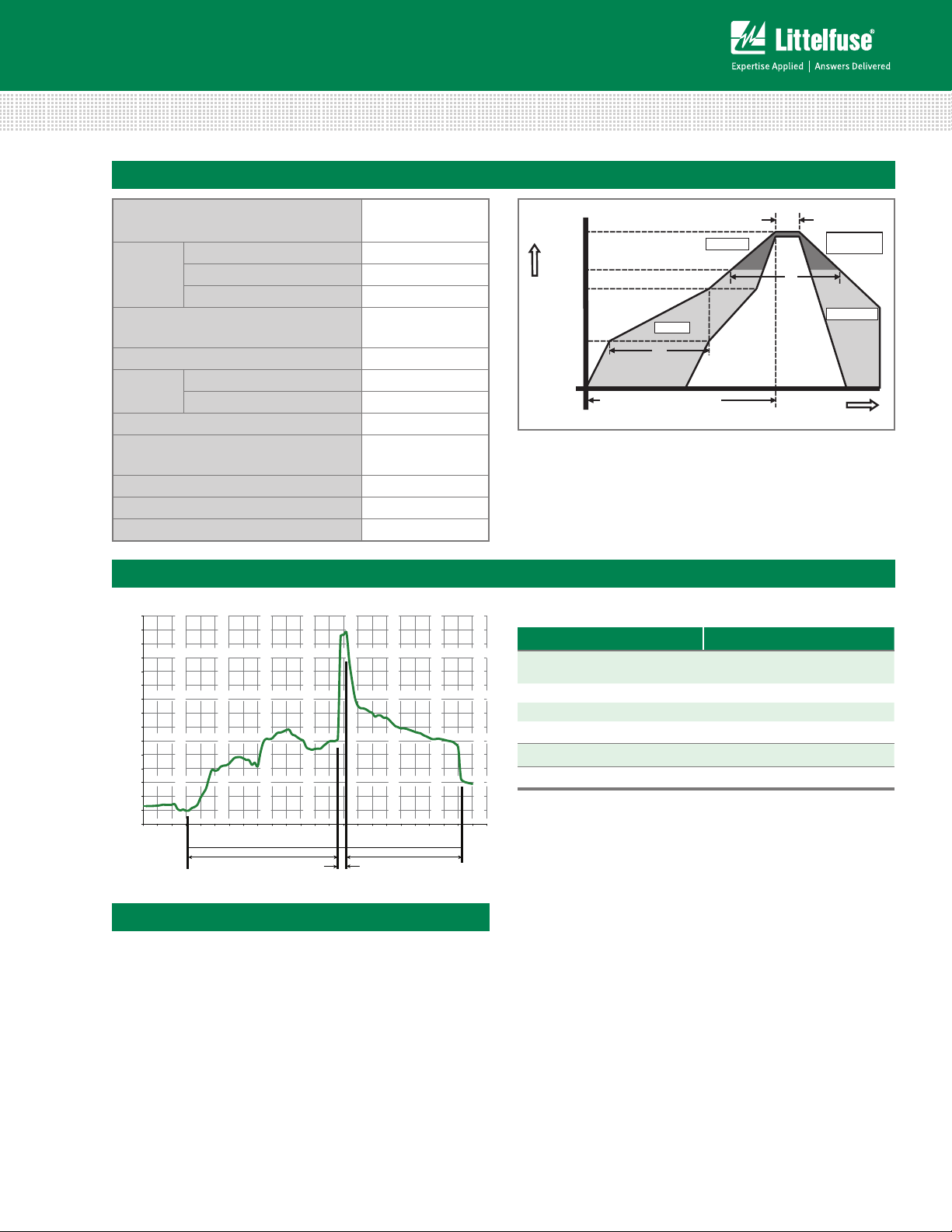
Soldering Parameters - Reflow Soldering (Surface Mount Devices)
Reflow Condition Pb – Free assembly
- Temperature Min (T
Pre Heat
- Temperature Max (T
- Time (Min to Max) (ts) 60 – 180 secs
Average ramp up rate (Liquidus Temp
(TL) to peak
T
to TL - Ramp-up Rate 5°C/second max
S(max)
Reflow
Peak Temperature (T
- Temperature (TL) (Liquidus) 217°C
- Temperature (t
) 60 – 150 seconds
L
) 260
P
Time within 5°C of actual peak
Temperature (t
)
p
Ramp-down Rate 6°C/second max
Time 25°C to peak Temperature (TP) 8 minutes Max.
Do not exceed 260°C
) 150°C
s(min)
) 200°C
s(max)
3°C/second max
+0/-5
°C
10 – 30 seconds
T
P
T
L
T
S(max)
T
S(min)
Temperature
25
Preheat
t
S
time to peak temperature
(t 25ºC to peak)
Ramp-up
t
P
Critical Zone
T
to T
L
P
t
L
Ramp-down
Time
Soldering Parameters - Wave Soldering (Thru-Hole Devices)
300
280
260
240
220
200
180
160
140
120
100
80
60
40
20
0
Temperature (°C) - Measured on bottom side of board
0
102030405060708090
Time (Seconds)
Preheat Time
100
110
120
130
140
150
160
170
180
190
200
210
220
230
Dwell Time
Cooling Time
Soldering Parameters - Hand Soldering
Solder Iron Temperature: 350° C +/- 5°C
Heating Time: 5 seconds max.
Recommended Process Parameters:
Wave Parameter Lead-Free Recommendation
Preheat:
(Depends on Flux Activation Temperature)
Temperature Minimum:
Temperature Maximum:
Preheat Time: 60-180 seconds
Solder Pot Temperature:
Solder Dwell Time: 2-5 seconds
240
(Typical Industry Recommendation)
100
° C
150
° C
° C Maximum
280
©2013 Littelfuse, Inc.
Specifications are subject to change without notice.
Please refer to www.littelfuse.com for current information.
Customer should verify actual device performance in their specific applications.
AC and CG3 Series
Revised: February 19, 2013
Page 4

Gas Discharge Tube (GDT) Products
AC and CG3 Series
Device Dimensions
Axial
PROFILE VIEW TOP VIEW
A
6.0 ± 0.2
[0.236 ± 0.008]
62 ± 2
[2.441 ± 0.079]
7.9 ± 0.3
[0.311 ± 0.012]
B
Core
PROFILE VIEW TOP VIEW
A
6.0 ± 0.2
[0.236 ± 0.008]
B
0.80 DIA. TYP.
[0.031]
0.80 DIA. TYP.
[0.031]
[0.314
[0.314
8.0 ± 0.2
[0.314
8.0 ± 0.2
[0.314
8.0 ± 0.2
± 0.008]
8.0 ± 0.2
± 0.008]
± 0.008]
± 0.008]
Part Numbering System and Ordering Information
Series
AC XXX XXX
AC Line Voltage
120 = 120V
240 = 240V
Lead / Packaging Option
= Core (no leads) / Bulk pack, 400 pcs per bag
L = Leaded / Bulk pack, 50 pcs per tray
LTR = Leaded / Tape & Reel, 500 pcs per reel
Series
CG3
Breakdown Voltage
1.0 = 1000V
1.1 = 1100V
1.2 = 1200V
1.3 = 1300V
1.5 = 1500V
2.0 = 2000V
2.5 = 2500V
2.7 = 2700V
3.0 = 3000V
3.3 = 3300V
4.0 = 4000V
4.5 = 4500V
5.0 = 5000V
6.2 = 6200V
6.5 = 6500V
7.5 = 7500V
Lead / Packaging Option
= Core (no leads) / Bulk pack, 400 pcs per bag
L = Leaded / Bulk pack, 50 pcs per tray
LTR = Leaded / Tape & Reel, 500 pcs per reel
Special Suffix Code
Enter this D004 special suffix code when placing orders
for CG36.2, CG36.5 and CG37.5 only
CG3 X.X XXX D004
7.9 ± 0.3
[0.311 ± 0.012]
Packaging Dimensions
For 'LTR' Option Code Axial Lead Items
<0.8 Max
52.4
[2.063]
22.8
[0.898]
6.4
[0.252]
5.0 Pitch
[0.197]
<1.2 Max. Lead Bend
80.0
[3.15]
254.0 - 356.0
[10.0 - 14.0]
Direction of Feed
AC and CG3 Series
Revised: February 19, 2013
Specifications are subject to change without notice.
©2013 Littelfuse, Inc.
Customer should verify actual device performance in their specific applications.
Please refer to www.littelfuse.com for current information.
 Loading...