

Page 1
Varistor Products
High Energy Industrial Disc Varistors > CA Series
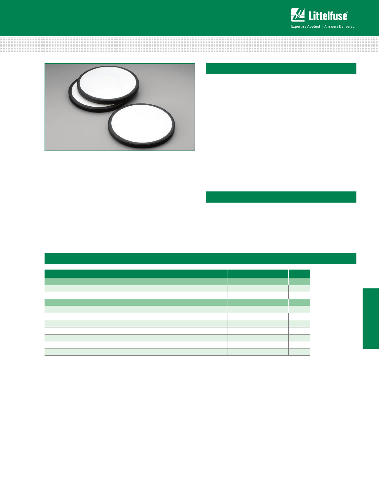
CA Varistor Series
Description
The CA Series of transient surge suppressors are industrial
high-energy disc varistors (MOVs) intended for special
applications requiring unique electrical contact or packaging
methods provided by the customer. The electrode finish
of these devices is solderable and can also be used with
pressure contacts. Discs of the same diameter may be
stacked.
This series of industrial disc varistors are nominal 60mm
diameter, with disc thickness ranging from 2.7mm to
32mm. The voltage range is 250V to 2800 V
(AC)RMS
.
For information on soldering considerations, refer to EC637
"Recommendations for Soldering Terminal Leads to MOV
Varistor Discs."
Features
• Standard disc size
nominal 60mm
diameter
• Discs have edge
passivation insulation
• High peak pulse
current range
50000A to 70000A
• Very high–energy
capability W
tm
880J to 10000J
Absolute Maximum Ratings
• For ratings of individual members of a series, see Device Ratings and Specifications chart
Continuous CA Series Units
Steady State Applied Voltage:
AC Voltage Range (V
DC Voltage Range (V
Transient:
Peak Pulse Current (ITM)
For 8/20μs Current Wave(See Figure 2) 20,000 to 70,000 A
Single-Pulse Energy Range
For 2ms Current Square Wave (W
Operating Ambient Temperature Range (T
Storage Temperature Range (T
Temperature Coefficient (V) of Clamping Voltage (V
CAUTION: Stresses above those listed in "Absolute Maximum Ratings" may cause permanent damage to the device. This is a stress only rating and operation
of the device at these or any other conditions above those indicated in the operational sections of this specification is not implied.
) - 55 to +85 °C
STG
) 250 to 2800 V
M(AC)RMS
) 330 to 3500 V
M(DC)
) 880 to 10,000 J
) -55 to +85 °C
A
TM
) at Specified Test Current <0.01 %/°C
C
MOV’S
CA Series
HI–ENERGY
© 2013 Littelfuse, Inc.
Specifications are subject to change without notice.
Please refer to www.littelfuse.com/series/ca.html for current information.
181
Revised: May 8, 2013
CA Varistor Series
Page 2
Varistor Products
High Energy Industrial Disc Varistors > CA Series
CA Series Ratings & Specifications
Maximum Rating (85°C) Specifications (25°C)
Continuous Transient
Part
Number
Device Branding
Size
Energy
(2ms)
WTM I
V
V
DC
M(DC)
V
RMS
V
M(AC)
Peak
Current
(8/20μs)
TM
Varistor Voltage at 1mA
DC Test Current
Min V
NOM
Max VC f = 1MHz
(mm) (V) (V) (J) (A) (V) (V) (V) (A) (pF)
V251CA60 60 250 330 880 50000 354 390 429 620 10000
V271CA60 60 275 369 950 50000 389 430 473 680 9000
V321CA60 60 320 420 1100 50000 462 510 561 760 7500
V421CA60 60 420 560 1500 70000 610 680 748 1060 6000
V481CA60 60 480 640 1600 70000 670 750 825 1160 5500
V511CA60 60 510 675 1800 70000 735 820 910 1300 5000
V571CA60 60 575 730 2100 70000 805 910 1000 1420 4500
V661CA60 60 660 850 2300 70000 940 1050 1160 1640 4000
V751CA60 60 750 970 2600 70000 1080 1200 1320 1880 3500
V881CA60 60 880 1150 3200 70000 1290 1500 1650 2340 2700
V112CA60
V142CA60
V172CA60
V202CA60
V242CA60
V282CA60
NOTE: Average power dissipation of transients should not exceed 2.5W for CA60 discs.
60
60
60
60
60
60
110 0
140 0
170 0
2000
2400
2800
140 0
1750
2150
2500
3000
3500
3800
5000
6000
7500
8800
10000
70000
70000
70000
70000
70000
70000
1620
2020
2500
2970
3510
4230
1800
2200
2700
3300
3900
4700
2060
2550
3030
3630
4290
5170
Max Clamping
Volt Vc at 200A
Current
(8/20μs)
2940
3600
4300
5200
6200
74 0 0
Typical
Capacitance
2200
1800
150 0
120 0
1000
800
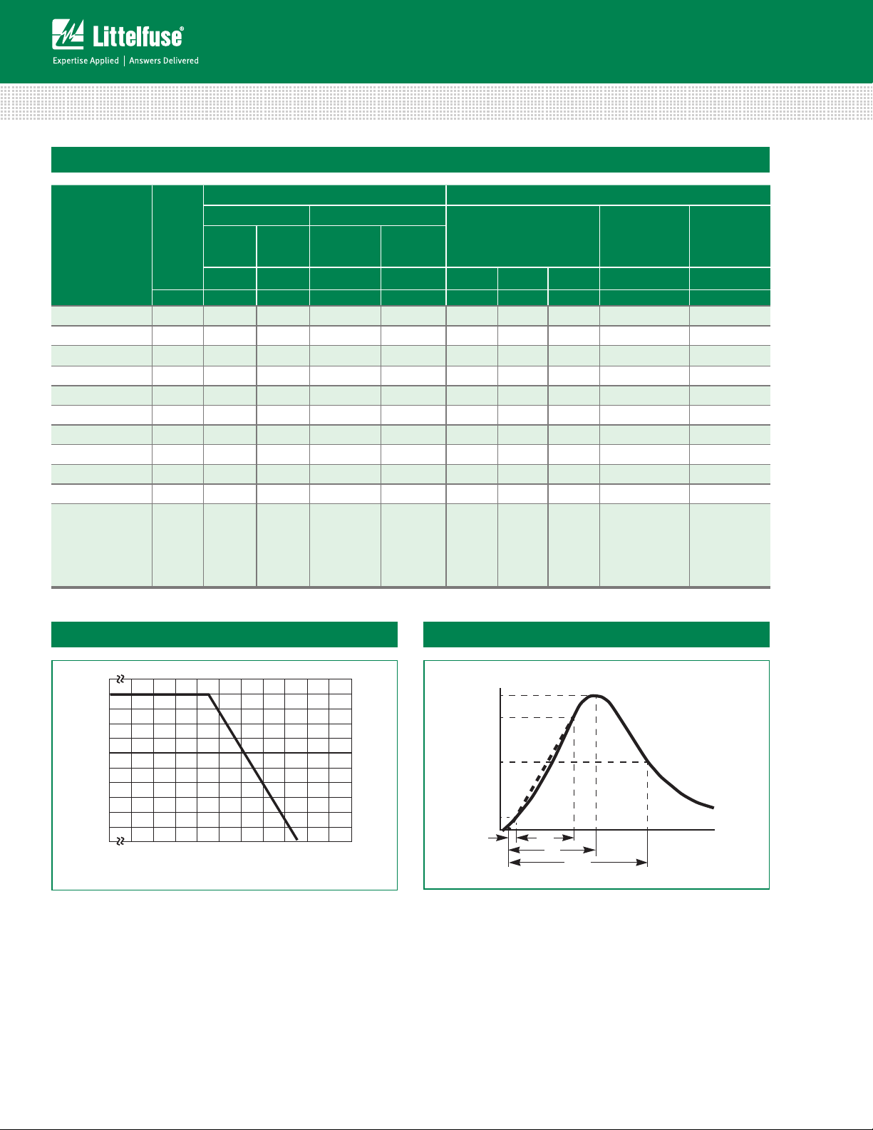
Power Dissipation Ratings
100
90
80
70
60
50
40
30
20
PERCENT OF RATED VALUE
10
0
-55 50 60 70 80 90 100 110 120 130 140 150
Figure 1
AMBIENT TEMPERATURE (
Should transients occur in rapid succession, the average power
dissipation result is the energy (watt-seconds) per pulse times
the number of pulses per second. The power so developed must
be within the specifications shown on the Device Ratings and
Specifications table for the specific device. Furthermore, the
operating values need to be derated at high temperatures as
shown in above. Because varistors can only dissipate a relatively
small amount of average power they are, therefore, not suitable
for repetitive applications that involve substantial amounts of
average power dissipation.
o
C)
Peak Pulse Current Test Waveform
100
90
50
10
O
1
Figure 2
01 = Virtual Origin of Wave
T = Time from 10% to 90% of Peak
T1 = Rise Time = 1.25 x T
T2 = Decay Time
Example - For an 8/20 μs Current Waveform:
8μs = T1 = Rise Time
20μs = T2 = Decay Time
T
T
1
T
2
TIME
CA Varistor Series
182
Revised: May 8, 2013
Please refer to www.littelfuse.com/series/ca.html for current information.
Specifications are subject to change without notice.
© 2013 Littelfuse, Inc.
Page 3

Varistor Products
High Energy Industrial Disc Varistors > CA Series
Maximum Clamping Voltage for 60mm Parts
V251CA60 - V881CA60
6,000
MAX CLAMPING VOLTAGE
5,000
DISC SIZE 60mm
4,000
250 TO 880V
3,000
T
= -55oC TO 85oC
A
2,000
V881CA60
V751CA60
V661CA60
V571CA60
1,000
900
800
700
V321CA60
600
V271CA60
500
V251CA60
MAXIMUM PEAK VOLTS (V)
400
300
200
-210-1100
10
Figure 3
V112CA60 - V282CA60
30,000
MAX CLAMPING VOLTAGE
DISC SIZE 60mm
1100 TO 2800V
20,000
T
= -55oC TO 85oC
A
10,000
9,000
8,000
7,000
6,000
V282CA60
5,000
V242CA60
V202CA60
4,000
MAX PEAK VOLTS (V)
V172CA60
3,000
V142CA60
V112CA60
2,000
-210-1100
10
Figure 5
RATING
M(AC)
PEAK AMPERES (A)
RATING
M(AC)
PEAK AMPERES (A)
10110210310410
10110210310410
V511CA60
V481CA60
V421CA60
Repetitive Surge Capability for 60mm Parts
V251CA60 - V321CA60
50,000
20,000
10,000
5,000
2,000
1,000
SURGE CURRENT (A)
5
Figure 4
V421CA60 - V282CA60
100,000
SURGE CURRENT (A)
5
Figure 6
NOTE: If pulse ratings are exceeded, a shift of V
+/-10% could result. This type of shift, which normally results in a decrease of V
result in the device not meeting the original published specifications, but does not prevent
the device from continuing to function, and to provide ample protection.
1
10
2
10
3
10
4
10
500
5
10
200
6
100
10
50
INDEFINITE
20
10
20
1
50,000
20,000
10
10,000
2
5,000
10
3
10
2,000
4
1,000
10
500
5
10
200
6
100
10
50
20
10
20 100 1,000 10,000
2
100
IMPULSE DURATION (μs)
2
INDEFINITE
IMPULSE DURATION (μs)
DISC SIZE 60mm
V251CA60 - V321CA60
1,000 10,000
DISC SIZE 60mm
V421CA60 - V282CA60
(at specified current) of more than
N(DC)
N(DC)
, may
MOV’S
CA Series
HI–ENERGY
© 2013 Littelfuse, Inc.
Specifications are subject to change without notice.
Please refer to www.littelfuse.com/series/ca.html for current information.
183
Revised: May 8, 2013
CA Varistor Series
Page 4

Varistor Products
High Energy Industrial Disc Varistors > CA Series
Physical Specifications
Soldering
Characteristics
Insulating Material glass passivation on edge only
Device Labeling none
Solderability per MIL–STD–202,
Method 208E
Product Dimensions (mm)
OPTIONAL
ELECTRODE
DIAMETER
(SEE TABLE)
2.5 mm
0.1 inch
Disc Diameter
Model
Size
Millimeters Inches
Min Max Min Max
60 58.0 62.0 2.283 2.441
Model
V
RMS
V
M(AC)
Millmeters Inches
Min. Max. Min. Max.
Disc Thickness
250 2.0 2.7 0.079 0.106
275 2.2 3.0 0.087 0.118
320 2.6 3.5 0.102 0.138
420 3.5 4.7 0.138 0.185
510 4.2 5.7 0.165 0.224
575 4.6 6.3 0.181 0.248
660 5.3 7.2 0.209 0.283
750 6.1 8.3 0.240 0.327
880 7.3 10.3 0.287 0.406
1100 9.2 13.0 0.362 0.512
1400 11.5 16.0 0.453 0.630
1700 14.0 19.0 0.551 0.748
2000 17.0 22.5 0.669 0.886
2400 20.0 27.0 0.787 1.063
2800 24.0 32.0 0.945 1.260
PASSIVATION
COLLAR
ELECTRODE
THICKNESS
Environmental Specifications
Operating/Storage
Temperature
Humidity Aging
Thermal Shock
Solvent Resistance MIL–STD–202, Method 215F
Moisture Sensitivity Level 1, J–STD–020C
-55°C to +85°C
+85°C, 85% RH, 1000 hours
+/-10% typical voltage change
+85°C to -55°C 10 times
+/-10% typical voltage change
Weight
Model Number
V251CA60 39
V271CA60 42
V321CA60 50
V421CA60 66
V481CA60 71
V511CA60 80
V571CA60 88
V661CA60 101
V751CA60 116
V881CA60 141
V112CA60 178
V142CA60 220
V172CA60 265
V202CA60 317
V242CA60 377
V282CA60 450
Typical Discweight
(Grams)
CA Varistor Series
184
Revised: May 8, 2013
Please refer to www.littelfuse.com/series/ca.html for current information.
Specifications are subject to change without notice.
© 2013 Littelfuse, Inc.
Page 5

Varistor Products
High Energy Industrial Disc Varistors > CA Series
Passivation Layer
The standard CA Series is supplied with passivation
layer around the outside perimeter of the disc forming
an electrical insulator as detailed in the dimensional
drawing. For other options contact factory. (See Ordering
Information)
Encapsulated Recommendations
After lead attachment, the disc/lead assembly may be
coated or encapsulated in a package to provide electrical
insulation and isolation from environmental contamination
as required by the application. Coating/Filler materials for
containers may include silicones, polyurethanes, and some
epoxy resins. Materials containing halogens, sulfides, or
alkalines are not recommended.
Stacking and Contact Pressure Recommendations
When applications require the stacking of CA60 discs,
or when an electrical connection is made by pressure
contacts, the pressure applied to the CA60 disc electrode
surface should be minimum 2.2kgs (5 pounds) and
maximum
4N/CM2 (5.7LBs/IN2).
Part Numbering System
Electrode Metallization
CA60 discs are supplied as standard with sintered Silver
electrodes. For other available options please contact
Littelfuse.
Recommended Reflow Temperature Profile
250
200
C)
o
150
100
TEMPERATURE (
50
0
0 100 200 300 400 500 600 700 800 900
TIME (SEC)
Packaging and Shipping
VARISTOR DESIGNATOR
MAX AC
(FIRST SIGNIFICANT DIGITS) V
V
M(AC)
SERIES DESIGNATOR
DISC SIZE (mm) DIAMETER
WORKING VOLTAGE
RMS
VOLTAGE DECADE MULTIPLIER
V 25 1 CA 60
M(AC)
The CA Series is supplied in bulk for shipment. Discs are
packaged in compartmentalized cartons to protect from
scratching or edge-chipping during shipment.
No branding or any other type of marking appears on the
CA disc itself.
CA60 discs are supplied as standard with sintered Silver
electrodes and glass passivation. For other available
options please contact factory.
MOV’S
CA Series
HI–ENERGY
© 2013 Littelfuse, Inc.
Specifications are subject to change without notice.
Please refer to www.littelfuse.com/series/ca.html for current information.
185
Revised: May 8, 2013
CA Varistor Series
 Loading...