

Page 1
Generator Control
LOAD
G GG
C6200
(Generator Control)
C6200
(Generator Control)
C6200
(Generator Control)
C6200
(Generator Control)
G GG
LOAD LOAD
BASIC
COMPACT
ADVANCED
BASIC
G GG G
C6200 C6200 C6200
C6200
C6200C6200C6200
C6200
(Generator Control)
C6200
(Generator Control)
LOAD LOAD
BASIC
COMPACT
ADVANCED
BASIC
G GG G
LOAD
G GG
C6200
(Generator Control)
C6200
(Generator Control)
C6200
(Generator Control)
LOAD LOAD
BASIC
COMPACT
ADVANCED
BASIC
G GG G
C6200
C6200C6200C6200
Basic and Advanced
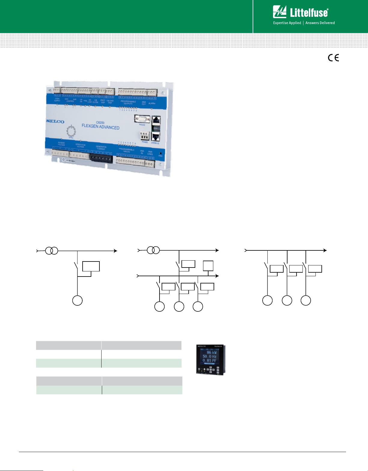
C6200 FLEXGEN SERIES
Generator Control
Description
FlexGen controllers are intended for paralleling of generators
with each other or with the grid. One FlexGen controller is
installed for each generator in the installation and handles all
electrical control.
There are two versions available, Basic and Advanced.
Both versions include basic functions such as autosynchronizing,
frequency control, active load sharing, dead bus monitoring and
reverse power protection. In addition the FlexGen Advanced
contains reactive load sharing, voltage matching, power factor
control, grid-parallel operation control, and protection against
excitation loss, RoCoF (df/dt), and vector shift. FlexGen Advanced
also contains over-current and short-circuit protection and power
management features like preferential load trip, load depending
start/stop and large consumer control.
Both models include MODBUS RTU interface enabling integration
with equipment from other manufacturers, for example, control
and monitoring from PC with a graphic SCADA interface. FlexGen
is type-approved by major marine classification societies and can
be used for marine power management systems.
Simplified Circuit Diagram
Grid Parallel Island ModeGrid Parallel with Local Bus
C6200
G
Ordering Information
ORDERING NUMBER MODEL NAME
C6200.0060 FlexGen Basic
C6200.0100 FlexGen Advanced
ACCESSORIES REQUIREMENT
C6500 Recommended
C6200
C6200C6200C6200
LOAD
C6200 C6200 C6200
G GG
G GG
Accessories
C6500 FlexGen UI User Interface Module
Provides indication of measurements, alarms,
alarm log and configuration of the generator
module.
The user interface is designed for mounting
in the switch panel door. It furnishes a large
back-lit display showing all electrical measurements and
control parameters.
g
User interface unit for any FlexGen controller
g
Separate LEDs provide clear indication
g
Valuable alarm log
g
Onsite configuration capability
g
Connects through the RS232 serial link
© 2013 Littelfuse Protection Relays & Controls
www.littelfuse.com/c6200
Rev: 4-A-050313
Page 2

Generator Control
Basic and Advanced
FlexGen Technical Data
FEATURES
3-phase true RMS measurement
Frequency control
Automatic synchronization
Active load sharing
Voltage control/Voltage matching
Reactive load sharing
Reverse power protection
Excitation loss protection
RoCoF protection (df/dt)
Vector shift protection
Overcurrent (I >) and
Overload protection (P>)
Short-circuit protection (I >>)
Overvoltage (U >)
Undervoltage (U <)
Overfrequency (F >)
Underfrequency (F <)
Dead bus monitoring /Black-out limiter
External circuit-breaker trip
Engine error trip
Preferential load trip (PM)
Load depending start/stop (PM)
Large consumer control (PM)
Dynamic grid-parallel operation control
Analog I/O
MODBUS RTU (RS485 interface)
Wiring Diagram
L1
L2
L3
BASIC ADVANCED
• •
• •
• •
• •
•
•
• •
•
•
•
•
•
• •
• •
• •
• •
• •
•
•
•
•
•
•
•
• •
Features & Benefits
FEATURES BENEFITS
3-phase true RMS
measurement
Analog outputs for speed
and voltage control
PWM outputs for speed
and voltage control
Pulse outputs for speed
and voltage control
10 programmable
Inputs and outputs
Type-approved by marine
classification societies
Reliable measurement, high noise immunity
Fits most electronic governors and ECUs
Compatible with e.g. CAT and Woodward
Compatible with conventional governors,
motorized potentiometers and some ECUs
Flexible configuration for a wide range of
applications such as marine PMS, on site
power or grid parallel applications
Approved for marine power management
Specifications
Auxiliary Supply 10 Vdc to 36 Vdc (24 Vdc-58%/+50%)
Generator Voltage 63 V-690 V
Generator Rated Frequency 50 Hz/60 Hz
C/T Secondary Current 5 A
Consumption 7 W
Burden C/T Input 0.4 VA at I
Ambient Temp Range –20°C to +70°C
Vibration IEC 60068-2-6
Humidity IEC 60068-2-30
EMC IEC 61000-4-3:2006, IEC 61000-4-6:2004,
IEC 61000-4-5:2005, IACS E10:2006 Test No.15,
CISPR 16-1:1999, CISPR 16-2:2002
Relay Contacts 230 Vac/2 A & 30 Vdc/2 A
External Communication MODBUS RTU
Enclosure IP20
Weight 1,5 Kg
Dimensions H 182 mm (7.2”); W 282 mm (11.1”);
D 50 mm (2.0”)
N
C/B
© 2013 Littelfuse Protection Relays & Controls
www.littelfuse.com/c6200
DG1
GND
1
31
2
29
40 41 42 43 44
GND
S1
C/B
L1 L2
+ -
Busbar
Aux.
Voltage
Supply
FLEX GEN GENERATOR CONTROL
C6200
Gen.
Gen.
Current
Voltage
S1/
S2/
L1 L2
ref pwm
L3
L3
5
14
6
13
32
Manual
alAn og O ut 1
Speed Control
33
Go verno r
Reset Alarm
Unload
Freq. Ctrl.
Disable
V/
mA
DC
34 35
45 46 47 48 49 50 51 52
C/B Close
Prg. Out. 1
ParallelLines
kW gnd
VAr
545556
26
27
28
Prot. Trip UnloadTrip
Prg. Out. 3
Prg. Out. 2
Alarm
66 67
65
53
C/B
GN D
2
1
L1
L2
Busbar
Voltage
Gen.
Voltage
L1
L2
6
5
S1
GND
29 31
42 43
40 41
44
Reset Alarm
Unload
C/B Block
C/B
Freq. Ctrl.
Disable
-
+
Aux.
Supply
FLEX GEN GENERATOR CONTROL
C6200
Gen.
Analog Out 1
Speed Control
ref
32
pwm
33
Go verno r
mA
34 35
ParallelLines
V/
kW
DC
26 27
Current
S2/
L3
13 14
S1/
L3
gnd
45
C/B Close
46
48 495051
47
52 53
Unload Trip
Prot. Trip
Prg.Out.3
Prg.Out.2
Prg.Out.1
545556
65 66
Alarm
67
VAr
28
DG2
Rev: 4-A-050313
 Loading...