

Page 1
Varistor Products
Radial Leaded Varistors > ATMOV Series
ATMOV Varistor Series
Epoxy Coated
Phenolic Coated
Agency Approvals
Agency Agency File Number
E320116 (only Epoxy coated)
Note: These parts are in compliance with AEC–Q200 (Table 10).
RoHS
Description
The Littelfuse ATMOV Series of low voltage, high surge current, radial leaded varistors provides an ideal circuit protection for load dump, jump start voltage transient conditions
specically for automotive applications.
The maximum peak surge current rating is rated up to 5kA
(8/20 μs pulse) to protect sensitive infotainment systems
from voltage transients. This AEC-Q200 (Table 10) compli
ant series is available in ve disc sizes: 5mm, 7mm, 10mm,
14mm and 20mm; it features a wide VDC voltage range from
16V to 50V.
Features
• Meets the stringent
quality standards of
AEC-Q200
(Table 10)
• Breakthrough in low
voltage varistor design
provides high peak
surge current rating
• Reduced footprint and
volume required for
surge protection
• Optional phenolic coating
for higher operating
temperature up to 125ºC
• Wide operating voltage
range: 14VAC to 42VAC
and 16VDC to 50VDC
• Five disc sizes available:
5, 7, 10, 14, and 20mm
• High resistance to
thermal cycles for
phenolic coating
• High energy absorption
particularly for automotive
load dump and jump start
• Lead–free, Halogen-Free
and RoHS compliant
• High peak surge
current rating up to
5kA (8/20 μs pulse)
-
Series
™
Applications
• Body Electronics Systems
• Powertrain Systems
• Infotainment Systems
• Automotive Control
Module Protection
• Motor or inductive load
transient suppression
Absolute Maximum Ratings
• For ratings of individual members of a series, see Device Ratings and Specications chart
Low Voltage Series Units
Continous:
Steady State Applied Voltage:
AC Voltage Range (V
DC Voltage Range (V
Transient:
Non-Repetitive Surge Current, 8/20µs Waveform (I
Non-Repetitive Energy Capability, 2ms Waveform (W
Operating Ambient Temperature Range (T
Operating Ambient Temperature Range (T
Storage Temperature Range (T
Storage Temperature Range (T
Temperature Coefficient (αV) of Clamping Voltage (V
Hi-Pot Encapsulation (Isolation Voltage Capability) for Epoxy coated 2500 V
Hi-Pot Encapsulation (Isolation Voltage Capability) for Phenolic coated 500 V
Epoxy Coating Insulation Resistance >1,000 MΩ
CAUTION: Stresses above those listed in "Absolute Maximum Ratings" may cause permanent damage to the device. This is a stress only rating and operation of
the device at these or any other conditions above those indicated in the operational sections of this specification is not implied.
© 2014 Littelfuse, Inc.
Specifications are subject to change without notice.
Revised: 02/18/14
) for Epoxy coated -40 to +125 °C
STG
) for Phenolic coated -40 to +150 °C
STG
) 14 to 42 V
M(AC)RMS
) 16 to 50 V
M(DC)
) 400 to 5,000 A
TM
) 1.0 to 140 J
) for Epoxy coated -40 to +85 °C
A
) for Phenolic coated -40 to +125 °C
A
) at Specified Test Current < 0.01% °C
C
TM
LV UltraMOV
1
Page 2
Varistor Products
Radial Leaded Varistors > ATMOV Series
ATMOV Series Device Ratings & Specifications
Epoxy
Coated
Models
Part Number
(Base part)
Branding
Phenolic
Coated
Models
Part Number
(Base part)
Branding
Max
Energy
Size
Disc
Dia.
(mm)
Max
Continuous
Voltage
V
RMSVDC
Varistor Voltage
at 1mA
Min Nom Max
Maximum
Clamping
Voltage
VCI
PKITM
Peak
Current
(8 x
20µs 1
pulse)
WTM
Rating
pulse)
(2ms,
1
Energy
Dump,
pulses)*
(V) (V) (V) (V) (V) (V) (A) (A) (J) (J) (V) (pF)
(Load
10
Jump
Start
DC
V
jump
(5
min)
Typical
Capaci-
tance
f =
1MHz
V05E14AUTO 5E14A V05P14AUTO 5P14A 5 14 16 19.8 22 24.2 43 1 400 1 6 25 110 0
V07E14AUTO 7E14A V07P14AUTO 7P14A 7 14 16 19.8 22 24.2 43 2.5 800 2.2 12 25 2450
V10E14AUTO 10E14A V10P14AUTO 10P14A 10 14 16 19.8 22 24.2 43 5 1500 5 25 25 4650
V14E14AUTO 14E14A V14P14AUTO 14P14A 14 14 16 19.8 22 24.2 43 10 3000 10 50 25 10200
V20E14AUTO 20E14A V20P14AUTO 20P14A 20 14 16 19.8 22 24.2 43 20 5000 28 10 0 25 22200
V05E17AUTO 5E17A V05P17AUTO 5P17A 5 17 20 24.3 27 29.7 53 1 400 1. 4 6 30 950
V07E17AUTO 7E17A V07P17AUTO 7P17A 7 17 20 24.3 27 29.7 53 2.5 800 2.8 12 30 2 10 0
V10E17AUTO 10E17A V10P17AUTO 10P17A 10 17 20 24.3 27 29.7 53 5 150 0 6.5 25 30 3900
V14E17AUTO 14E17A V14P17AUTO 14P17A 14 17 20 24.3 27 29.7 53 10 3000 13 50 30 8700
V20E17AUTO 20E17A V20P17AUTO 20P17A 20 17 20 24.3 27 29.7 53 20 5000 35 10 0 30 18750
V05E25AUTO 5E25A V05P25AUTO 5P25A 5 25 28 35.1 39 42.9 77 1 400 2.5 6 40 750
V07E25AUTO 7E25A V07P25AUTO 7P25A 7 25 28 35.1 39 42.9 77 2.5 800 5.5 12 40 1500
V10E25AUTO 10E25A V10P25AUTO 10P25A 10 25 28 35.1 39 42.9 77 5 150 0 13 25 40 2900
V14E25AUTO 14E25A V14P25AUTO 14P25A 14 25 28 35.1 39 42.9 77 10 3000 25 50 40 6200
V20E25AUTO 20E25A V20P25AUTO 20P25A 20 25 28 35.1 39 42.9 77 20 5000 77 10 0 40 13500
V05E30AUTO 5E30A V05P30AUTO 5P30A 5 30 34 42.3 47 51.7 93 1 400 3.1 6 45 650
V07E30AUTO 7E30A V07P30AUTO 7P30A 7 30 34 42.3 47 51.7 93 2.5 800 7 12 45 1350
V10E30AUTO 10E30A V10P30AUTO 10P30A 10 30 34 42.3 47 51.7 93 5 1500 15.5 25 45 2550
V14E30AUTO 14E30A V14P30AUTO 14P30A 14 30 34 42.3
47 51.7 93 10 3000 32 50 45 5550
V20E30AUTO 20E30A V20P30AUTO 20P30A 20 30 34 42.3 47 51.7 93 20 5000 90 10 0 45 12000
V05E42AUTO 5E42A V05P42AUTO 5P42A 5 42 50 61.2 68 74.8 135 1 400 5 6 55 500
V07E42AUTO 7E42A V07P42AUTO 7P42A 7 42 50 61.2 68 74.8 135 2.5 800 11 12 55 1000
V10E42AUTO 10E42A V10P42AUTO 10P42A 10 42 50 61.2 68 74.8 135 5 1500 25 25 55 1850
V14E42AUTO 14E42A V14P42AUTO 14P42A 14 42 50 61.2 68 74.8 135 10 3000 50 50 55 4000
V20E42AUTO 20E42A V20P42AUTO 20P42A 20 42 50 61.2 68 74.8 135 20 5000 140 10 0 55 8500
Note: 1. Average power dissipation of transients not to exceed 0.2W, 0.25W, 0.4W, 0.6W or 1W for model sizes 5mm, 7mm, 10mm, 14mm and 20mm, respectively.
*2. Energy rating (auto load dump) for impulse duration of 40ms minimum to one half of peak current, 60sec interval (ISO7637-2 5a).
3. The shift of Vnom ( Varistor Volatge ) may be to +/-15% for Load dump or Jump Start test.
2
Specifications are subject to change without notice.
© 2014 Littelfuse, Inc.
Revised: 02/18/14
Page 3
Varistor Products
100
90
80
70
60
50
40
30
20
10
0
-55 50 60 70 80 90 100110 120130 14 0150
AMBIENT TEMPERATURE (
o
C)
PERCENT OF RATED VALUE
100
90
80
70
60
50
40
30
20
10
0
-55 50 60 70 80 90 100110 120130 140150
AMBIENT TEMPERATURE (
o
C)
PERCENT OF RATED VALUE
Radial Leaded Varistors > ATMOV Series
Current Energy and Power Dissipation Ratings
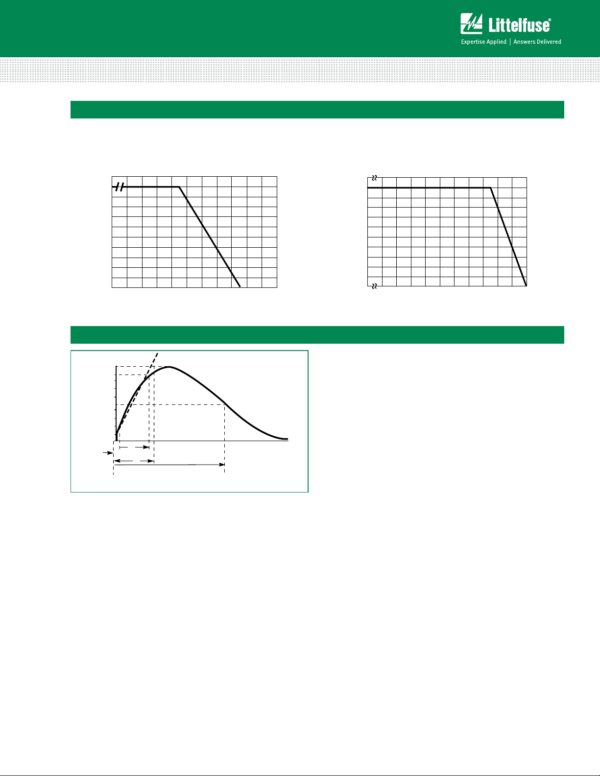
Figure 1A - Power Derating for Epoxy Coated
For applications exceeding 85ºC ambient temperature,
the peak surge current and energy ratings must be
reduced as shown below.
Peak Pulse Current Test Waveform for Clamping Voltage
100
50
Figure 1B - Power Derating for Phenolic Coated
For applications exceeding 125ºC ambient temperature,
the peak surge current and energy ratings must be
reduced as shown below.
Series
™
PERCENT OF PEAK VALUE
0
O
1
t
t
1
Figure 2: Peak Pulse Current Test Waveform for Clamping Voltage
01 = Virtual Origin of Wave
t = Time from 10% to 90% of Peak
t1 = Virtual Front Time = 1.25 x t
t2 = Virtual Time to Half-Value (Impulse Duration)
Example - For an 8/20 µs Current Waveform:
8µs = t1 = Virtual Front Time
20µs = t2 = Virtual Time to Half-Value
© 2014 Littelfuse, Inc.
Specifications are subject to change without notice.
Revised: 02/18/14
LV UltraMOV
TIME
t
2
3
Page 4

Varistor Products
500
400
300
200
100
90
80
70
60
50
40
30
20
10
MAXIMUM PEAK VOLTS (V)
10
-3
10
-2
10
-1
10
0
10
1
10
2
10
3
MAXIMUM CLAMPING VOLTAGE
PEAK AMPERES (A)
V07x42AUTO
V07x30AUTO
V07x25AUTO
V07x17AUTO
V07x14AUTO
MODEL SIZE 7mm
600
500
400
300
200
100
90
80
70
60
50
40
30
20
MAXIMUM PEAK VOLTS (V)
PEAK AMPERES (A)
10
-2
10
-1
10
0
10
1
10
2
10
3
MAXIMUM CLAMPING VOLTAGE
MODEL SIZE 5mm
10
V05x42AUTO
V05x30AUTO
V05x25AUTO
V05x17AUTO
V05x14AUTO
10
-3
500
400
300
200
100
90
80
70
60
50
40
30
20
10
MAXIMUM PEAK VOLTS (V)
10
-3
10
-2
10
-1
10
0
10
1
10
2
10
3
MAXIMUM CLAMPING VOLTAGE
PEAK AMPERES (A)
V07x42AUTO
V07x30AUTO
V07x25AUTO
V07x17AUTO
V07x14AUTO
MODEL SIZE 7mm
V07x14AUTO - V07x42AUTO
500
400
300
200
100
90
80
70
60
50
40
30
20
10
MAXIMUM PEAK VOLTS (V)
10
-3
10
-2
10
-1
10
0
10
1
10
2
10
3
MAXIMUM CLAMPING VOLTAGE
PEAK AMPERES (A)
V07x42AUTO
V07x30AUTO
V07x25AUTO
V07x17AUTO
V07x14AUTO
MODEL SIZE 7mm
500
400
300
200
100
90
80
70
60
50
40
30
20
10
MAXIMUM PEAK VOLTS (V)
10
-3
10
-2
10
-1
10
0
10
1
10
2
10
3
PEAK AMPERES (A)
V10x42AUTO
V10x30AUTO
V10x25AUTO
V10x17AUTO
V10x14AUTO
MAXIMUM CLAMPING VOLTAGE
MODEL SIZE 10mm
600
500
400
300
200
100
90
80
70
60
50
40
30
20
10
-3
10
-2
10
-1
10
0
10
1
10
2
10
3
PEAK AMPERES (A)
MAXIMUM PEAK VOLTS (V)
V14x42AUTO
V14x30AUTO
V14x25AUTO
V14x17AUTO
V14x14AUTO
MAXIMUM CLAMPING VOLTAGE
MODEL SIZE 14mm
CLAMPING VOLTAGE FOR V05x14AUTO - V05x42AUTO
600
500
400
300
200
100
90
80
70
60
50
40
30
20
MAXIMUM PEAK VOLTS (V)
PEAK AMPERES (A)
10
-2
10
-1
10
0
10
1
10
2
10
3
MAXIMUM CLAMPING VOLTAGE
MODEL SIZE 5mm
10
V05x42AUTO
V05x30AUTO
V05x25AUTO
V05x17AUTO
V05x14AUTO
10
-3
CLAMPING VOLTAGE FOR
V07x14AUTO - V07x42AUTO
500
400
300
200
100
90
80
70
60
50
40
30
20
10
MAXIMUM PEAK VOLTS (V)
10
-3
10
-2
10
-1
10
0
10
1
10
2
10
3
MAXIMUM CLAMPING VOLTAGE
PEAK AMPERES (A)
V07x42AUTO
V07x30AUTO
V07x25AUTO
V07x17AUTO
V07x14AUTO
MODEL SIZE 7mm
600
500
400
300
200
100
90
80
70
60
50
40
30
20
10
-3
10
-2
10
-1
10
0
10
1
10210
3
PEAK AMPERES (A)
MAXIMUM PEAK VOLTS (V)
V14x42AUTO
V14x30AUTO
V14x25AUTO
V14x17AUTO
V14x14AUTO
MAXIMUM CLAMPING VOLTAGE
MODEL SIZE 14mm
CLAMPING VOLTAGE FOR
V07x14AUTO - V07x42AUTO
V10x14AUTO - V10x42AUTO
V14x14AUTO - V14x42AUTO
500
400
300
200
100
90
80
70
60
50
40
30
20
10
MAXIMUM PEAK VOLTS (V)
10
-3
10
-2
10
-1
10
0
10
1
10
2
10
3
MAXIMUM CLAMPING VOLTAGE
PEAK AMPERES (A)
V07x42AUTO
V07x30AUTO
V07x25AUTO
V07x17AUTO
V07x14AUTO
MODEL SIZE 7mm
500
400
300
200
100
90
80
70
60
50
40
30
20
10
MAXIMUM PEAK VOLTS (V)
10
-3
10
-2
10
-1
10
0
10
1
10
2
10
3
PEAK AMPERES (A)
V10x42AUTO
V10x30AUTO
V10x25AUTO
V10x17AUTO
V10x14AUTO
MAXIMUM CLAMPING VOLTAGE
MODEL SIZE 10mm
600
500
400
300
200
100
90
80
70
60
50
40
30
20
10
-3
10
-2
10
-1
10
0
10
1
10
2
10
3
PEAK AMPERES (A)
MAXIMUM PEAK VOLTS (V)
V14x42AUTO
V14x30AUTO
V14x25AUTO
V14x17AUTO
V14x14AUTO
MAXIMUM CLAMPING VOLTAGE
MODEL SIZE 14mm
CLAMPING VOLTAGE FOR V05x14AUTO - V05x42AUTO
600
500
400
300
200
100
90
80
70
60
50
40
30
20
MAXIMUM PEAK VOLTS (V)
PEAK AMPERES (A)
10
-2
10
-1
10
0
10
1
10
2
10
3
MAXIMUM CLAMPING VOLTAGE
MODEL SIZE 5mm
10
V05x42AUTO
V05x30AUTO
V05x25AUTO
V05x17AUTO
V05x14AUTO
10
-3
MAXIMUM PEAK VOLTS (V)
PEAK AMPERES (A)
10-210-110010110210310
4
10
-3
10-510
-4
10
-6
CLAMPING VOLTAGE FOR
CLAMPING VOLTAGE FOR CLAMPING VOLTAGE FOR
10
20
30
40
50
60
70
80
90
600
700
800
900
100
200
300
400
500
1000
MAXIMUM CLAMPING VOLTAGE
MODEL SIZE 20mm
V20x14AUTO
V20x17AUTO
V20x25AUTO
V20x30AUTO
V20x42AUTO
Radial Leaded Varistors > ATMOV Series
Maximum Clamping Voltage for 5mm Parts
V05x14AUTO - V05x42AUTO
Maximum Clamping Voltage for 10mm Parts
V10x14AUTO - V10x42AUTO
Maximum Clamping Voltage for 7mm Parts
V07x14AUTO - V07x42AUTO
Maximum Clamping Voltage for 14mm Parts
V14x14AUTO - V14x42AUTO
Maximum Clamping Voltage for 20mm Parts
V20x14AUTO - V20x42AUTO
4
Specifications are subject to change without notice.
© 2014 Littelfuse, Inc.
Revised: 02/18/14
Page 5

Varistor Products
10 100 1000 10000
5MM V05E14...E42AUTO
Surge Current (A)
Impulse Duration (µs)
7MM V07E14....E42AUTO
1
10
100
1000
10000
1x
2x
15x
10
2
x
10
3
x
10
4
x
10
5
x
10
6
x
7MM V07E14....E42AUTO
10 100 1000 10000 10 100 1000 10000
Surge Current (A)
Impulse Duration (µs)
5MM V05E14...E42AUTO
Surge Current (A)
Impulse Duration (µs)
7MM V07E14....E42AUTO
1
10
100
1000
10000
10MM V10E14...E42AUTO
Surge Current (A)
Impulse Duration (µs)
14MM V14E14...E42AUTO
1x
2x
15x
10
2
x
10
3
x
10
4
x
10
5
x
10
6
x
0.1
1
10
100
1000
1
10
100
1000
10000
10 100 1000 10000
1x
2x
15x
10
2
x
10
3
x
10
4
x
10
5
x
10
6
x
1x
2x
15x
10
2
x
10
3
x
10
4
x
10
5
x
10
6
x
Surge Current (A)
Impulse Duration (µs)
7MM V07E14....E42AUTO
14MM V14E14...E42AUTO
1
10
100
1000
10000
1x
2x
15x
10
2
x
10
3
x
10
4
x
10
5
x
10
6
x
10 100 1000 10000 10 100 1000 10000
Surge Current (A)
Impulse Duration (µs)
5MM V05E14...E42AUTO
Surge Current (A)
Impulse Duration (µs)
7MM V07E14....E42AUTO
1
10
100
1000
10000
1
10
100
1000
10000
Surge Current (A)
Impulse Duration (µs)
10MM V10E14...E42AUTO
Surge Current (A)
Impulse Duration (µs)
14MM V14E14...E42AUTO
20MM V20E14...E42AUTO
1x
2x
15x
10
2
x
10
3
x
10
4
x
10
5
x
10
6
x
0.1
1
10
100
1000
1
10
100
1000
10000
10 100 1000 10000
10 100 1000 10000
1x
2x
15x
10
2
x
10
3
x
10
4
x
10
5
x
10
6
x
1x
2x
15x
10
2
x
10
3
x
10
4
x
10
5
x
10
6
x
1x
2x
15x
10
2
x
10
3
x
10
4
x
10
5
x
10
6
x
Radial Leaded Varistors > ATMOV Series
Repetitive Surge Capability for 5mm Parts
V05x14AUTO – V05x42AUTO
Repetitive Surge Capability for 7mm Parts
V07x14AUTO – V07x42AUTO
1000
1x
2x
15x
100
2
10
x
3
10
x
4
x
10
5
x
10
6
10
x
10
Repetitive Surge Capability for 10mm Parts
V10x14AUTO – V10x42AUTO
1
Surge Current (A)
0.1
10 100 1000 10000
Impulse Duration (µs)
Surge Current (A)
Repetitive Surge Capability for 14mm Parts
V14x14AUTO – V14x42AUTO
10000
1000
Surge Current (A)
1x
2x
15x
2
10
x
3
10
x
4
100
10
x
5
10
x
6
x
10
10
1
10 100 1000 10000
Impulse Duration (µs)
Repetitive Surge Capability for 20mm Parts
V020x14AUTO – V20x42AUTO
10000
1000
Surge Current (A)
100
1x
2x
15x
2
10
x
3
x
10
4
10
x
5
x
10
6
10
x
10
1
10 100 1000 10000
Impulse Duration (µs)
NOTE: If pulse ratings are exceeded, a shift of V
more then +/-10% could result. This type of shift, which normally results in a
decrease of V
specications, but does not prevent the device from continuing to function,
and to provide ample protection.
Surge Current (A)
10000
1000
100
1x
2x
15x
2
x
10
3
10
x
4
10
x
5
10
x
6
10
x
10
1
10 100 1000 10000
Impulse Duration (µs)
10000
1x
2x
15x
1000
100
2
10
x
3
x
10
4
10
x
5
10
x
6
10
x
10
1
10 100 1000 10000
Impulse Duration (µs)
(at specied current) of
N(DC)
, may result in the device not meeting the original published
N(DC)
Series
™
LV UltraMOV
© 2014 Littelfuse, Inc.
Specifications are subject to change without notice.
Revised: 02/18/14
5
Page 6

Wave Solder Profile
300
S)
TEMPERATURE (ºC)
300
TEMPERATURE (ºC)
Varistor Products
Radial Leaded Varistors > ATMOV Series
Non Lead–free Profile
250
200
150
100
50
0
00.5 11.5 22.5 33.5 4
Maximum Wave 240C
TIME(MINUTE
Physical Specifications
Lead Material Copper Clad Steel Wire
Soldering
Characteristics
Insulating Material
Solderability per MIL–STD–202,
Method 208E
Cured, ame retardant epoxy polymer
meets UL94V–0 requirements
Lead–free Profile
250
200
150
100
50
0
00.5 11.5 22.5 33.5 4
Maximum Wave 260C
TIME(MINUTES)
Environmental Specifications
Humidity Aging
Thermal Shock
Solvent Resistance MIL–STD–202, Method 215F
+85°C, 85% RH,1000 hours
+/-10% typical voltage change
+85°C to -40°C 10 times
+/-10% typical voltage change
Device Labeling Marked with LF, voltage and date code
Moisture Sensitivity Level 1, J–STD–020C
6
Specifications are subject to change without notice.
© 2014 Littelfuse, Inc.
Revised: 02/18/14
Page 7

Varistor Products
Radial Leaded Varistors > ATMOV Series
Product Dimensions (mm)
øD
A
e
V
RMS
Model
øb
e1 e1
L
E
Dimen-
sion
Voltage
A All -
A1 All -
ØD All -
e All
11 - 30
e
1
35 - 40
11 - 30 -
E
35 - 40 -
Øb All
L All
L
TRIM
All 2.41 (0.095)
øD
A1
SEATING
PLANE
L
E
øb
e
5mm Size 7mm Size 10mm Size 14mm Size 20mm Size
Min.
mm (in)
4
(0.157)6 (0.236)4 (0.157)6 (0.236)
1
(0.039)3 (0.118)1 (0.039)3 (0.118)1 (0.039)3 (0.118)
1. 5
(0.059)
0.585
(0.023)
25.4
(1.00)
Max.
mm (in)
10
(0.394)
13
(0.512)
7
(0.276)
3.5
(0.138)
5.0
(0.197)
5.6
(0.220)
0.685
(0.027)
-
4.69
(0.185)
Min.
mm (in)
-
-
-
1.5
(0.059)
-
-
0.585
(0.023)
25.4
(1.00)
2.41
(0.095)
Max.
mm (in)
12
(0.472)
15
(0.591)
9
(0.354)
3.5
(0.138)
5.0
(0.197)
5.6
(0.220)
0.685
(0.027)
-
4.69
(0.185)
Min.
mm (in)
-
-
-
6.5
(0.256)
1.5
(0.059)
-
-
0.76
(0.030)
25.4
(1.00)
2.41
(0.095)
Max.
mm (in)
16
(0.630)
19.5
(0.768)
12.5
(0.492)
8.5
(0.335)
3.5
(0.138)
5.0
(0.197)
5.6
(0.220)
0.86
(0.034)
-
4.69
(0.185)
Min.
mm (in)
-
-
-
6.5
(0.256)
Max.
mm (in)
20
(0.787)
22.5
(0.886)
17
(0.669)
8.5
(0.335)
Min.
mm (in)
-
-
-
6.5
(0.256)
1
(0.039)3 (0.118)1 (0.039)3 (0.118)
1.5
(0.059)
-
-
0.76
(0.030)
25.4
(1.00)
2.41
(0.095)
3.5
(0.138)
5.0
(0.197)
5.6
(0.220)
0.86
(0.034)
-
4.69
(0.185)
1.5
(0.059)
-
-
0.76
(0.030)
25.4
(1.00)
2.41
(0.095)
Max.
mm (in)
26.5
(1.043)
29
(1.142)
23
(0.906)
8.5
(0.335)
3.5
(0.138)
5.0
(0.197)
5.6
(0.220)
0.86
(0.034)
-
4.69
(0.185)
Series
™
LV UltraMOV
© 2014 Littelfuse, Inc.
Specifications are subject to change without notice.
Revised: 02/18/14
7
Page 8

Tape and Reel Specifications
P1
P0
W0
E
DP
DH
DH
W1
W
F
t
W2
P
DP
C
Db
H0
DD0
H1
SEATING
PLANE
P2
Crimped Leads "ZT"
Crimped Leads "ZT"
P1
P0
E
DP
DH
DH
W1
W
F
t
W2W0
P
DP
C
Db
H0
DD0
H1
SEATING
PLANE
P2
P1
P0
W0
E
DP
DH
DH
W1
W
F
t
W2
P
DP
C
Db
H0
DD0
H1
SEATING
PLANE
P2
DH
E
DH
DP
W1
W
F
t
W2
P
DP
Db
H
DD0
H1
P1
P2
W0
Crimped Leads "ZT"
P1
P0
W0
E
DP
DH
DH
W1
W
F
t
W2
P
DP
C
Db
H0
DD0
H1
SEATING
PLANE
P2
Crimped Leads "ZT"
Crimped Leads "ZT"
Straight Leads "ZS"
Straight Leads "ZS"
P1
P0
E
DP
DH
DH
W1
W
F
t
W2W0
P
DP
C
Db
H0
DD0
H1
SEATING
PLANE
P2
P1
P0
W0
E
DP
DH
DH
W1
W
F
t
W2
P
DP
C
Db
H0
DD0
H1
SEATING
PLANE
P2
P0
DH
E
DH
DP
W1
W
F
t
W2
P
DP
Db
H
DD0
H1
P1
P2
W0
P1
P0
P2
DH
E
DH
DP
W1
W
F
t
W2W0
P
DP
Db
H
DD0
H1
H
P0
U
DH
E
DH
DP
W1
W
F
t
W2
P
DP
Db
Ho
DD0
H1
P2
W0
P1
Crimped Leads "ZT"
Straight Leads "ZS"
P1
P0
W0
E
DP
DH
DH
W1
W
F
t
W2
P
DP
C
Db
H0
DD0
H1
SEATING
PLANE
P2
P0
DH
E
DH
DP
W1
W
F
t
W2
P
DP
Db
H
DD0
H1
P1
P2
W0
5 and 7mm Devices 10, 14 and 20mm Devices
STRAIGHT LEADS "L1" STRAIGHT LEADS "L1"
P2
P
DP
Varistor Products
Radial Leaded Varistors > ATMOV Series
E
DP
DH
DH
P2
P
DP
E
DP
DH
DH
H1
DD0
H1
DD0
1
DD0
H1
W1
H
P1
Db
P0
F
t
W2W0
W
H
DD0
P1
P0
Db
F
CRIMPED LEADS "L2" CRIMPED LEADS "L2"
P2
SEATING
PLANE
H0
P1
P0
P
DP
C
Db
F
E
DP
DH
DH
W1
W2W0
W
t
H1
H0
DD0
SEATING
PLANE
P2
P1
P0
P
DP
C
Db
F
UNDER CRIMPED / IN-LINE LEADS "L3" UNDER CRIMPED / IN-LINE LEADS "L3"
P2
Ho
P1
P
DP
P0
Db
F
E
DP
DH
DH
U
W1
W2W0
W
t
H1
Ho
DD0
P2
P1
P0
P
DP
Db
F
W0
W1
W2
W
t
E
DP
DH
DP
DH
DH
W1
W2
W0
W
t
E
DH
U
W0
W1
W2
W
t
Refer to next page for dimension measurement specifics.
8
© 2014 Littelfuse, Inc.
Specifications are subject to change without notice.
Revised: 02/18/14
Page 9

Varistor Products
Radial Leaded Varistors > ATMOV Series
Tape and Reel Specifications (continued)
NOTES:
• Radial devices on tape are supplied with crimped leads, straight leads, or under-crimped leads
• Leads are offset by product dimension e1
• Conforms to ANSI and EIA specications
• Can be supplied to IEC Publication 286-2
SYMBOL DESCRIPTION
P Pitch of Component 12.7 +/- 1.0 12.7 +/- 1.0 25.4 +/- 1.0 25.4 +/- 1.0 25.4 +/- 1.0
Feed Hole Pitch 12.7 +/- 0.2 12.7 +/- 0.2 12.7 +/- 0.2 12.7 +/- 0.2 12.7 +/- 0.2
P
0
Feed Hole Center to Pitch 3.85 +/- 0.7 3.85 +/- 0.7 8.85 +/- 0.7 8.85 +/- 0.7 8.85 +/- 0.7
P
1
Hole Center to Component Center 6.35 +/- 1.0 6.35 +/- 1.0 12.7 +/- 0.7 12.7 +/- 0.7 12.7 +/- 0.7
P
2
F Lead to Lead Distance 5.0 +/- 1.0 5.0 +/-1.0 7.5 +/- 1.0 7.5 +/- 1.0 7.5 +/- 1.0
h Component Alignment 2.0 Max 2.0 Max 2.0 Max 2.0 Max 2.0 Max
W Tape Width 18.0 +1.0 / -0.5 18.0 +1.0 / -0.5 18.0 +1.0 / -0.5 18.0 +1.0 / -0.5 18.0 +1.0 / -0.5
Hold Down Tape Width 12.0 +/- 0.3 12.0 +/- 0.3 12.0 +/- 0.3 12.0 +/- 0.3 12.0 +/- 0.3
W
0
Hole Position 9.0 +0.75 / -0.50 9.0 +0.75 / -0.50 9.0 +0.75 / -0.50 9.0 +0.75 / -0.50 9.0 +0.75 / -0.50
W
1
Hold Down Tape Position 0.5 Max 0.5 Max 0.5 Max 0.5 Max 0.5 Max
W
2
Height from Tape Center to
H
Component Base
Seating Plane Height 16.0 +/- 0.5 16.0 +/- 0.5 16.0 +/- 0.5 16.0 +/- 0.5 16.0 +/- 0.5
H
0
Component Height 29.0 Max 32.0 Max 36.0 Max 40.0 Max 46.5 Max
H
1
Feed Hole Diameter 4.0 +/- 0.2 4.0 +/- 0.2 4.0 +/- 0.2 4.0 +/- 0.2 4.0 +/- 0.2
D
0
t Total Tape Thickness 0.7 +/- 0.2 0.7 +/- 0.2 0.7 +/- 0.2 0.7 +/- 0.2 0.7 +/- 0.2
U Undercrimp Width 8.0 Max 8.0 Max 8.0 Max 8.0 Max 8.0 Max
p Component Alignment 3° Max 3º
5mm 7mm 10mm 14mm 20mm
18.0 +2.0 / -0.0 18.0 +2.0 / -0.0 18.0 +2.0 / -0.0 18.0 +2.0 / -0.0 18.0 +2.0 / -0.0
Max 3° Max 3° Max 3° Max
MODEL SIZE
Series
™
LV UltraMOV
Part Numbering System
V05E
Littelfuse Varistor
Disc Size
05, 07, 10, 14 or 20 mm
Coating
E: Epoxy
P: Phenolic
VM(AC)RMS
14V to 42V
ATMOV Series
Lead-Free, RoHS and
Halogen free Compliant
© 2014 Littelfuse, Inc.
Specifications are subject to change without notice.
Revised: 02/18/14
14 XXXXX
AUTO L1 B
Other
Non-Standard Options
Packaging
Blank or B: Bulk Pack
T: Ta pe and Reel
A: Ammo Pack
Lead Formation
Blank or L1: Straight
L2: Crimped
L3: In-Line
L4: Trim/Crimp (Bulk pack only)
9
 Loading...