

Page 1
Transient Voltage Suppression Diodes
Axial Leaded – 10kA > AK10 series
AK10 Series
Agency Approvals
AGENCY AGENCY FILE NUMBER
E128662
Maximum Ratings and Thermal Characteristics
=25°C unless otherwise noted)
(T
A
Parameter Symbol Value Unit
Operating Junction Temperature
Range
Operating Junction Temperature
Range
Current Rating
Note: 1. Rated IPP measured with 8/20μs pulse.
1
T
STG
T
J
I
PP
(-)55 to 150 °C
(-)55 to 150 °C
10 kA
RoHS
Description
The AK10 series of high current transient suppressors have
been specially designed for use in A.C. line protection and
any demanding applications (AC or DC).They offer superior
clamping characteristics over standard S.A.D. technologies
by virtue of the Littelfuse Foldbak technology. Therefore,
any voltage rise due to increased current conduction is
contained to a minimum, providing the best possible
protection level. They can also be connected in series and/
or parallel to create very high capacity protection solutions.
Features
• Verylowclampingvoltage
• Ultracompact:less
than one-tenth the size
of traditional discrete
solutions
• Sharpbreakdownvoltage
• Lowsloperesistance
• Bi-directional
• Foldbaktechnologyfor
superior clamping factor
• Symmetricinleadswidth
for easier soldering during
• IEC-61000-4-2ESD
15kV(Air), 8kV (Contact)
• ESDprotectionofdata
lines in accordance with
IEC 61000-4-2 (IEC801-2)
• EFTprotectionofdata
lines in accordance with
IEC 61000-4-4 (IEC801-4)
• Halogen-free
• RoHScompliant
• Glasspassivatedjunction
assembly
Additional Information
Functional Diagram
Bi-directional
Electrical Characteristics (T
Part
Numbers
AK10 - 030C
AK10 - 058C
AK10 - 066C
AK10 - 076C
AK10 - 170C
AK10 - 190C
AK10 - 240C
AK10 - 380C
AK10 - 430C
AK10 - 530C
Note: Using 8/20µS wave shaped defined in IEC 61000-4-5.
© 2014 Littelfuse, Inc.
Specifications are subject to change without notice.
Revised: 03/04/14
Marking
10-015C 30 10 15 32 37 10 58 10,000 0.1 11.0 X
10-058C 58 10 15 64 70 10 110 10,000 0.1 6.5 X
10-066C 66 10 15 72 80 10 120 10,000 0.1 6.5 X
10-076C 76 10 15 85 95 10 140 10,000 0.1 6.5 X
10-170C 170 10 15 180 220 10 260 10,000 0.1 2.8 X
10-190C 190 10 15 200 245 10 290 10,000 0.1 2.5 X
10-240C 240 10 15 250 285 10 340 10,000 0.1 2.2 X
10-380C 380 10 15 401 443 10 520 10,000 0.1 2.0 X
10-430C 430 10 15 440 490 10 625 10,000 0.1 1.4 X
10-530C 530 10 15 560 619 10 750 10,000 0.1 1.0 X
Part
Standoff
Voltage
(VSO)
Volts
=25°C unless otherwise noted)
A
Max.
Reverse
Leakage
(I
) @VSO
R
µA
Typical
IR @
85°C
(µA)
Datasheet
Resources
Samples
Max.
Reverse
Breakdown
Voltage (VBR) @ I
Min Volts Max Volts (mA) VCL Volts IPP Amps (%/°C) (nF)
Current
T
Test
Max. Clamping Voltage
VCL @ Ipp Peak Pulse
I
Current (IPP) (Note 1)
T
Max. Temp
Coefficient
OF V
BR
Capaci-
tance
0 Bias
10kHz
Agency
Approval
Page 2
Transient Voltage Suppression Diodes
0
20
40
60
80
100
0255075 100 125
Percent of Rated Value
T - AMBI ENT TEMPERATURE (°C)
A
Current (kA)
Voltage (V)
0
50
100
150
200
250
300
0 0.5 1 1.5 2 2.5 3 3.5 4
TIME(MINUTES)
TEMPERATURE
(
º
C)
Maximum W ave 240C
0
50
100
150
200
250
300
0 0.5 1 1.5 2 2.5 3 3.5 4
TIME(MINUTES)
TEMPERATURE
(ºC)
Maximum W ave 260C
Axial Leaded – 10kA > AK10 series
Physical Specifications
Weight Contact manufacturer
Case Epoxy encapsulated
Terminal
Silver plated leads, solderable per
MIL-STD-750, Method 2026
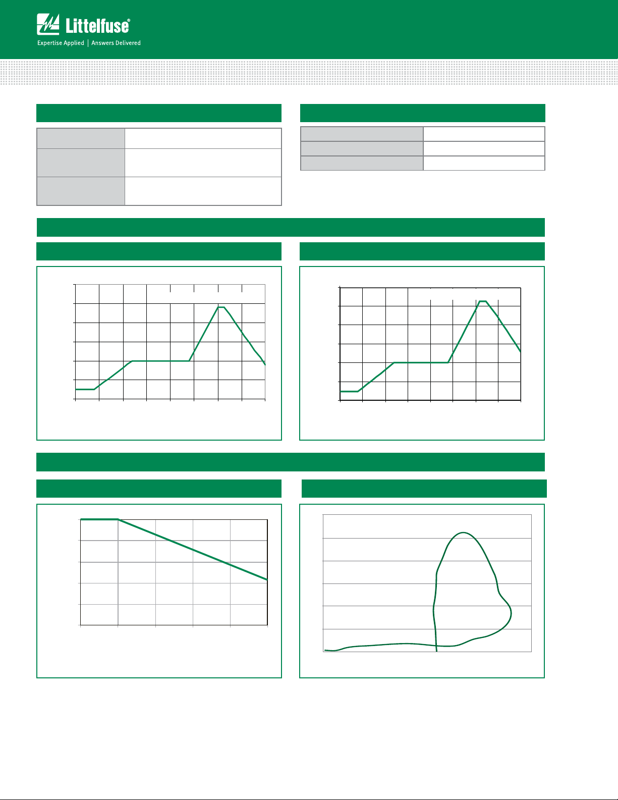
Wave Solder Profile
Figure 1 - Non Lead-free Profile
Flow/Wave Soldering (Solder Dipping)
Peak Temperature : 265°C
Dipping Time : 10 seconds
Soldering : 1 time
Figure 2 - Lead-free Profile
Ratings and Characteristic Curves
Figure 3 - Peak Power Derating
(T
=25°C unless otherwise noted)
A
Figure 4- Surge Response
continues on next page.
Specifications are subject to change without notice.
© 2014 Littelfuse, Inc.
Revised: 03/04/14
Page 3
Transient Voltage Suppression Diodes
A
C
50
100
0
t
r
t
d
0
Peak
Value
Half Value
t – Time (µs)
I
PP
– Peak Pulse Current – %I
PP
tr = rise time to peak value
t
d
= decay time to half value
t
r
x t
d
=8/20µs
1
10
100
100000
0.00001 0.0001 0.001
P
PPM
-Peak Pulse Power (kW)
td-Pulse Width (sec.)
1000
AK10-430C
10000
AK10-076C
8/20µs
10/350µs
10/1000µs
-8
-6
-4
-2
0
2
4
6
8
10
12
-50 -25025 50 75 100 125
Percent of V
BR
Change
Junction Temperature(Tj )
Axial Leaded – 10kA > AK10 series
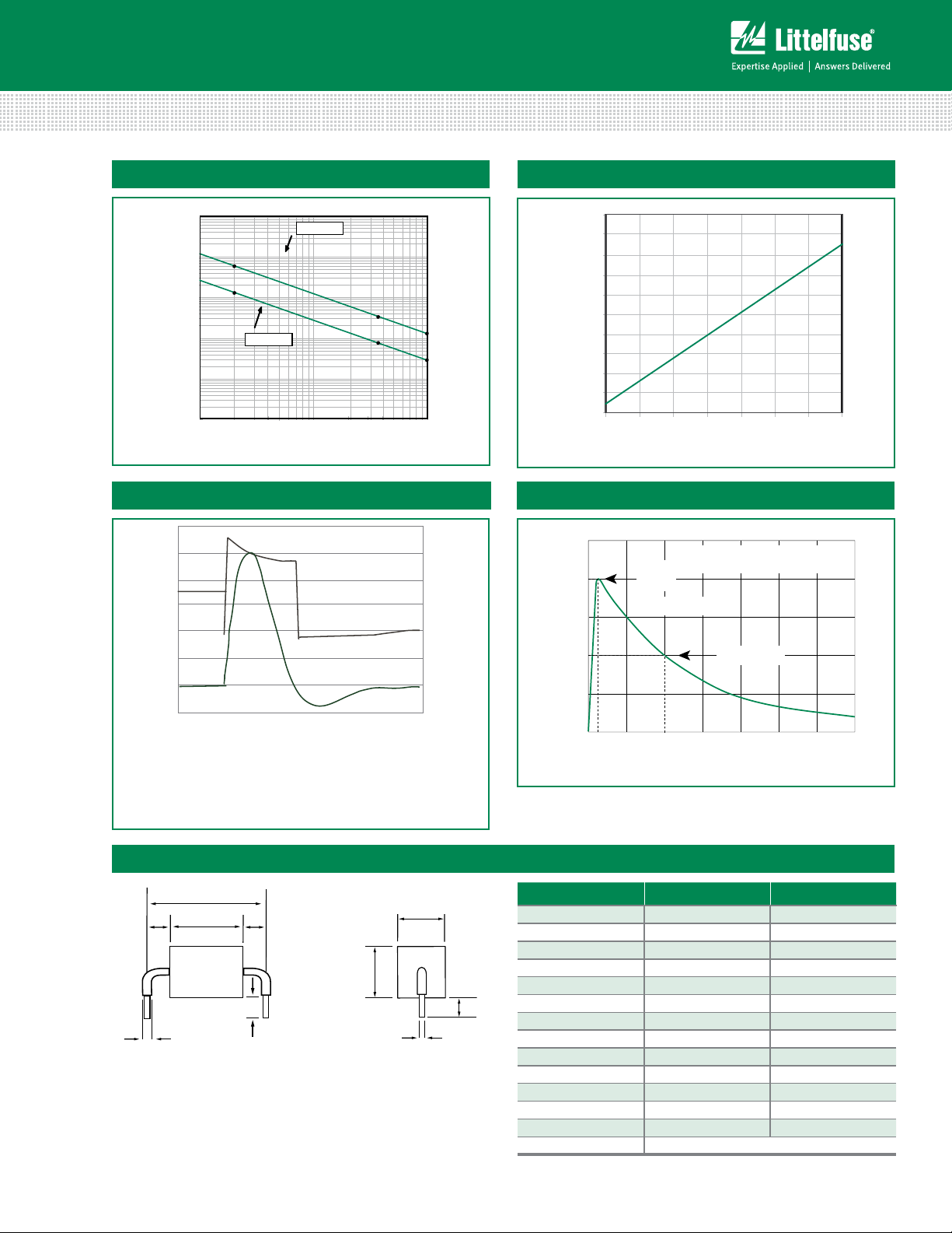
Figure 5 - Typical Peak Pulse Power Rating Curve Figure 6 - Typical V
Figure 7 - Surge Response (8/20 Surge current waveform)
Voltage
Figure 8 - Pulse Waveform
Vs Junction Temperature
BR
Notes:
The power dissipation causes a change in avalanche
voltage during the surge and the avalanche voltage
eventually returns to the original value when the
transient has passed
Dimensions
G
L2
© 2014 Littelfuse, Inc.
Specifications are subject to change without notice.
Revised: 03/04/14
B
Current
L1
Time (µs)
F
A 0.950 +/- 0.04 24.15 +/- 1.00
A - 530C 1.370 +/- 0.08 34.70 +/- 2.00
B 0.095 +/- 0.024 2.40 +/- 0.60
Dimensions Inches Millimeters
D
C 0.236 +/- 0.04 6.00 +/- 1.00
D 0.570 max. 14.48 max.
C
E 0.050 +/- 0.002 1.27 +/- 0.05
F 0.500 max. 12.70 max.
E
G - 030C 0.167 +/- 0.04 4.23 +/- 1.00
G - 058C/066C/076C 0.200 +/- 0.04 5.08 +/- 1.00
G - 170C/190C 0.362 +/- 0.04 9.20 +/- 1.00
G - 240C 0.420 +/- 0.04 10.67 +/- 1.00
G - 380C/430C 0.650 +/- 0.04 16.50 +/- 1.00
G - 530C 1.060 +/- 0.06 27.00 +/- 1.50
L1/L2 L1 = L2 tolerance +/- 0.04 inch (1.0 mm)
Page 4
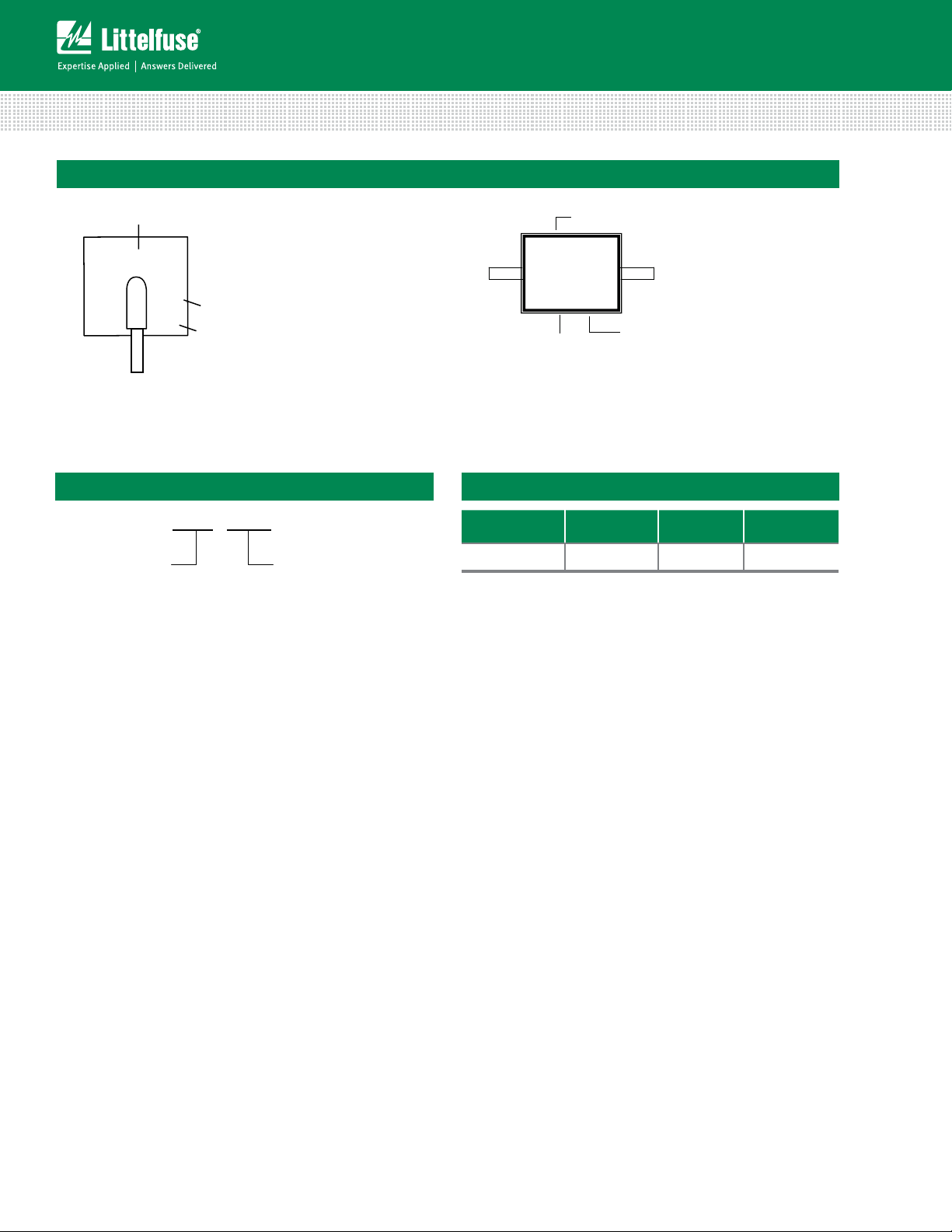
Part Marking System
Characteristics Chart)
AK10 XXXX
Transient Voltage Suppression Diodes
Axial Leaded – 10kA > AK10 series
Part Marking
10-XXXX
L
F
YWW
Littelfuse Logo
Trace Code Marking
Y:Year Code
WW: Working Week Code
Type 1 - Side View
Part Numbering System
Series Type
Apply to P/N listed below:
AK10-030C
AK10-058C
AK10-066C
AK10-076C
Stand Off Voltage
(Please Refer to Electrical
Littelfuse Logo
L
10-xxxx
F
YWW
Trace Code Marking
Y:Year Code
WW: Working Week Code
Type 2- Top View
Part Marking
Apply to P/N listed below:
AK10-170C
AK10-190C
AK10-240C
AK10-380C
AK10-430C
AK10-530C
Packing Options
Part Number
AK10-XXXX AK Package 56 Bulk
Component
Package
Quantity
Packaging
Option
Specifications are subject to change without notice.
© 2014 Littelfuse, Inc.
Revised: 03/04/14
 Loading...