

Page 1
AF0100
ARC-FLASH RELAY
Instruction Manual
REVISION 0-B-013118
E-mail: techline@littelfuse.com
Tel: +1-800-832-3873
www.littelfuse.com/AF0100
Document Number: PM-1430-EN
Copyright © 2018 Littelfuse
All rights reserved.
Page 2

AF0100 Arc-Flash Relay
This page intentionally left blank.
Page i
REV. 0-B-013118
Page 3

AF0100 Arc-Flash Relay
TABLE OF CONTENTS
1 KEY FEATURES ......................................................1
1.1 Easy Installation ......................................1
1.2 Fail-Safe Operation .................................. 1
1.3 Fast Error and Fault Location ................... 1
1.4 USB Interface ........................................... 1
2 ARC-FLASH PROTECTION SYSTEM DESIGN
3 SENSOR PLACEMENT
........................................... 5
3.1 General Guidelines ..................................5
3.2 Switchgear Protection .............................5
3.3 Transformer Protection ............................5
3.4 Generator Protection ...............................5
4 OPTICAL SENSORS
...............................................6
4.1 PGA-LS10 Photoelectric Point Sensor
with Sensor Check ................................... 7
4.1.1 PGA-LS10 Connection .............................8
4.1.2 PGA-LS10 Installation .............................9
4.2 PGA-LS20 and PGA-LS30
Fiber-Optic Sensors with
Sensor Check ......................................... 10
4.2.1 Fiber Connection ....................................10
4.2.2 Receiver Wiring Connections ................10
4.2.3 Transmitter Wiring Connections ...........10
4.2.4 PGA-LS20 and PGA-LS30 Connection ....
4.2.5 Fiber-Optic Sensor Adjustment .............12
4.2.6 Sensor Adjustment For a Fiber Length
Other Than 60 cm (24 in) ....................... 12
...... 3
11
Page ii
REV. 0-B-013118
7 USER INTERFACE
................................................ 18
7.1 Reset Button .......................................18
7.2 LED Indication and
Relay Operation ..................................18
7.3 USB Conguration Software ...............20
7.3.1 USB Conguration Software –
Screen Examples .................................21
7.4 Firmware Upgrade ..............................24
8 COMMISSIONING
............................................... 25
8.1 Conguration of Installed Sensors .....25
8.2 Testing the Sensors ............................ 25
8.3 Testing the TRIP 1 and TRIP 2 Outputs
and Associated Circuit Breakers ........26
8.4 Full Operation Test..............................26
9 SUPPORT RESOURCES
.......................................27
9.1 Sending Information for Support ................27
10 SPECIFICATIONS
................................................. 28
10.1 AF0100 ...............................................28
10.2 EMC Tests ..........................................29
10.3 Environmental Tests ........................... 29
10.4 Safety ................................................. 30
10.5 Certication ........................................ 30
10.6 Sensors ...............................................31
10.7 Ordering Information ..........................32
10.8 Related Products ................................32
10.9 Warranty ............................................32
5 APPLICATION EXAMPLES
................................... 13
5.1 Basic Scenario: One Sensor –
One Circuit Breaker ...............................13
5.2 Total Clearing Time ...............................14
5.2.1 Arc-Detection Delay ..............................14
5.2.2 Circuit Breaker Operating Time .............14
5.2.3 Total Clearing Time Examples ...............14
6 INSTALLATION AND TERMINALS
6.1 Power Supply.......................................16
6.1.1 Line AC Supply (optional) .................... 16
6.1.2 Station Battery DC Supply (optional) ..16
6.1.3 Auxiliary DC Supply ............................. 16
6.1.4 Supply Surveillance ............................. 16
6.2 Inputs and Outputs .............................. 17
6.2.1 ERROR Signal Relay ............................17
6.3 Sensors ................................................17
6.3.1 Light Immunity Adjustment ................. 17
6.3.2
Extending or Shortening Cable Length ....
..................... 15
17
Page 4

AF0100 Arc-Flash Relay
Page iii
REV. 0-B-013118
APPENDIX A: INSTALLATION LOG SHEET
.............34
APPENDIX B: REDUNDANT TRIP
CIRCUIT DESCRIPTION
APPENDIX C: AF0100 REVISION HISTORY
.............................................35
.............36
LIST OF FIGURES
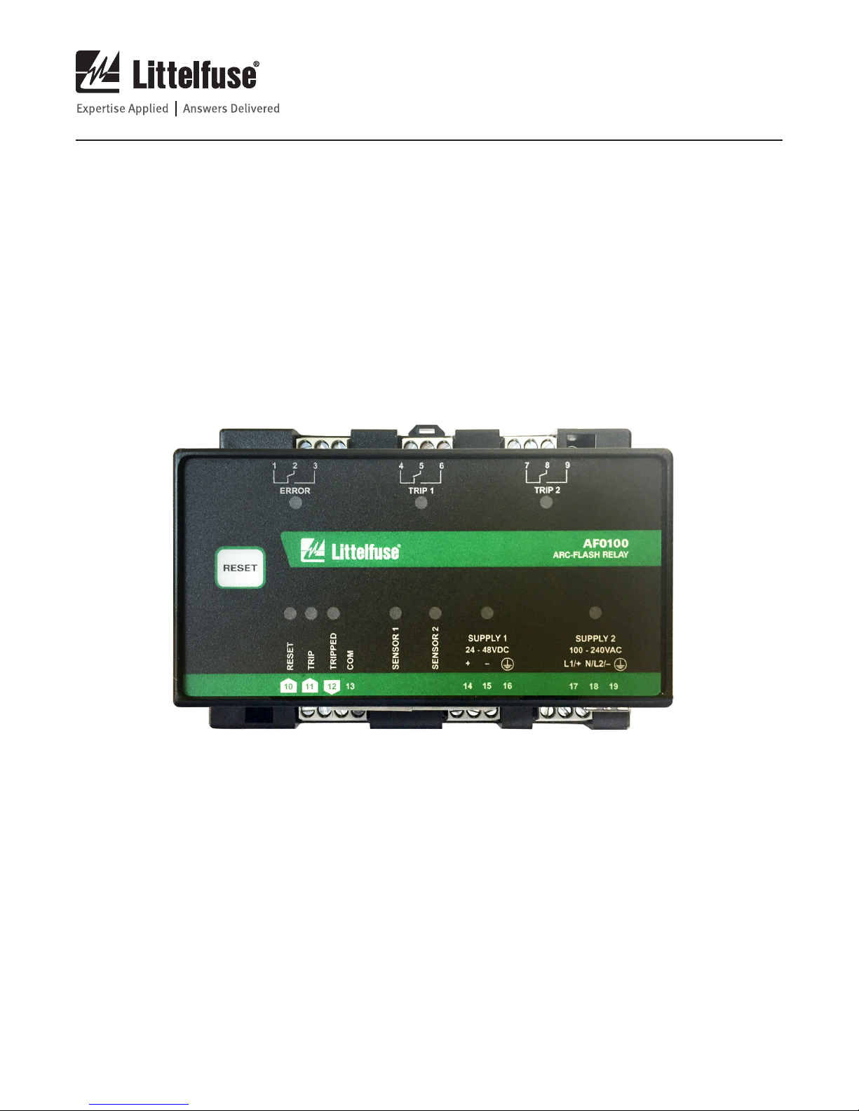
1 AF0100 Top View (ordering option
AF0100-00 shown) ....................................... 2
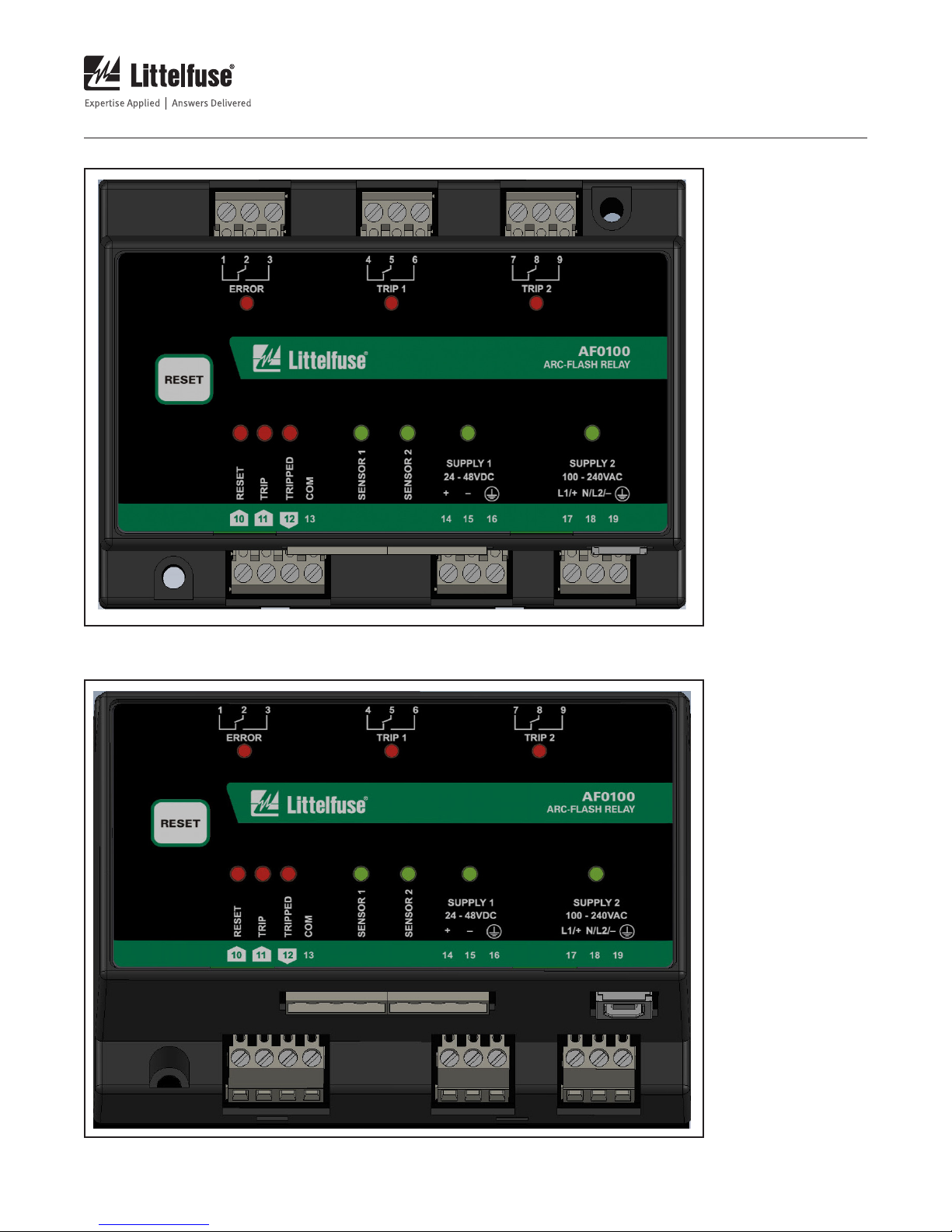
2 AF0100 with Sensor and USB View
(ordering option AF0100-00 shown) ............ 2
3 AF0100 Typical Wiring Diagram ..................4
4
PGA-LS10 Detection Range for a
3 kA Fault .........................................................
5 PGA-LS10 Connection Diagram ...................8
6 PGA-LS10 Mounting Detail .........................9
7 PGA-LS20 and PGA-LS30
Connection Diagram .................................. 11
8 Basic AF0100 Conguration ......................13
9 AF0100 Outline And
Mounting Details ....................................... 15
10 TRIP and ERROR Relays
Maximum Switching Capacity ....................33
7
LIST OF TABLES
1 Circuit Breaker Operating Time .................14
2 AF0100 Firmware Upgrade Sequence ......24
3
Sample Table for Testing a System
............26
Page 5

AF0100 Arc-Flash Relay
Page 1
REV. 0-B-013118
1 KEY FEATURES
The AF0100 Arc-Flash Relay is a high-speed, arc-detection
device for electrical power-distribution systems. The AF0100
has two Form-C Trip relays, and has inputs for up to two
optical sensors for optimal arc detection. The inputs support
both point sensors and fiber-optic line sensors, which cover
a larger area.
Using optical sensors rather than relying strictly on current
measurement allows a much faster detection time than
overcurrent relays or a circuit breaker alone can typically
provide, as the light from the arc is unique to arc faults,
whereas current pulses above the nominal level are part of
normal operation for many systems.
On the occurrence of an arc fault, the AF0100 detects the
fault and activates the trip relays, which trips the circuit
breaker(s) supplying the fault. In a typical system, a trip occurs
within 5ms. The total arcing time is effectively reduced to
the mechanical opening time of the circuit breaker, typically
between 30 and 75 milliseconds. This reduces the energy of
the arc fault significantly, increasing worker safety, reducing
fault damage, and improving uptime.
The AF0100 can be used on ac or dc electrical systems and
can be powered from either an ac or dc supply, or both. For
all available ordering options, see section 10.7.
1.1 Easy Installation
The relay will automatically learn which sensors and
power supplies are connected, and will indicate an alarm
if a previously connected wire breaks or is unplugged. If a
configuration change is needed, the redetection process
can be triggered by pressing the Reset button for 20 s, see
section 7.1.
1.2 Fail-Safe Operation
The AF0100 continuously monitors its internal circuitry as
well as the connected optical sensors. Any system faults,
including a sensor-cable fault, are indicated by an Error relay
and the Error LED on the front panel.
A redundant trip circuit ensures that the AF0100 will trip
the circuit breaker on an arc flash even if a primary tripcircuit component fails (shunt trip mode only). The design
of the redundant trip circuit also provides a significantly
faster response to an arc on power-up (for example, after
maintenance during a shutdown) than is possible with
microprocessor-only relays, which is an advantage in smaller
self-powered systems.
1.3 Fast Error and Fault Location
The optical sensors used with the AF0100 have built-in LED’s
for indication of health and for easy location of arc faults.
The AF0100 also has one LED per optical sensor on the front
panel to indicate which sensor(s) have caused a trip and for
indicating problems in the installation.
The AF0100 includes two sensor inputs, two trip relays,
one error relay, and a digital input and output interface
which makes it possible to connect additional AF0100 or
AF0500 units. See Fig. 1. The complete configuration and
“programming” of the system can be done by simply wiring
the inputs and outputs marked with green arrows – no
external software is needed.
A system with multiple zones and upstream circuit breakers
can be implemented such that in many applications, the
switchboard wiring diagram can completely describe how
the arc-flash system works.
1.4 USB Interface
A USB interface on the lower panel of the AF0100 provides
easy PC access to configuration settings. No PC driver or
software installation is required.
Page 6
AF0100 Arc-Flash Relay
Page 2
REV. 0-B-013118
FIGURE 1. AF0100 Top View (ordering option AF0100-00 shown).
FIGURE 2. AF0100 with Sensor and USB View (ordering option AF0100-00 shown).
Page 7

AF0100 Arc-Flash Relay
Page 3
REV. 0-B-013118
2 ARC-FLASH PROTECTION SYSTEM DESIGN
In order to find the necessary components and configuration
for protecting a system, a single line diagram and knowledge
of the physical configuration of the system is needed.
1. Start by identifying the number and type of sensors
that are needed to have coverage of the complete
system. In order to have complete coverage, all
bus bar sections, circuit breaker connection points,
and bolted connections must have a sensor nearby.
Typically, a single point sensor per enclosed
switchgear compartment is sufficient, but if a large
internal component is blocking the line-of-sight, an
additional sensor may be necessary. A fiber sensor
can be threaded along a bus bar to protect many
compartments, but only if they are interrupted by
the same circuit breaker. The fiber sensor can also
be used to improve coverage of compartments with
many bulky components.
2. Identify which circuit breakers to open in order to
completely interrupt all current to each sensor. If
more sensors are isolated by the same set of circuit
breakers, these are said to be in the same zone – an
arc-flash event on any of these sensors will open the
same set of circuit breakers.
4. Based on the number of sensors and zones, the
necessary number of outputs and sensors can be
found. Each AF0100 provides one zone (one or two
circuit breaker outputs) and two sensor inputs, which
can be bundled into larger zones by a single wire, and
which can combine fiber and point sensors completely
as needed.
5. Now, place one AF0100 trip output for each circuit
breaker in the system. If there are more than two
sensors per zone, connect additional AF0100 or
AF0500 zones together by connecting the “TRIP” and
“TRIPPED” terminals in all zones. Zones can also be
made larger by using a sensor covering a larger area,
i.e. by changing point sensors to fiber sensors. Place
the sensors in the cabinets, and connect them to the
zone inputs. The sensor cables, which use copper
wire, can be shortened or extended as needed.
3. Identify if the system needs coordinated tripping – if
upstream circuit breakers, which trips the incoming
feeder for several downstream circuit breakers, are
present in the system, a decision must be made to
either merge all the smaller zones and trip all circuit
breakers at once (fast and inexpensive, but may trip
more outgoing feeders than necessary), or to only
trip the upstream circuit breaker if the downstream
circuit breaker fails to interrupt the current (slower
and costlier, but trips only what is necessary).
Page 8
AF0100 Arc-Flash Relay
N
L1 L1
N N
Protection
Active
G
Tri p
R
L1
A B C
x x x
Tri p
Coil
Page 4
REV. 0-B-013118
A B C
Reset
L1 L1
Protection
G
Active
N
Tri p
R
N N
L1
Tri p
Coil
N
x x x
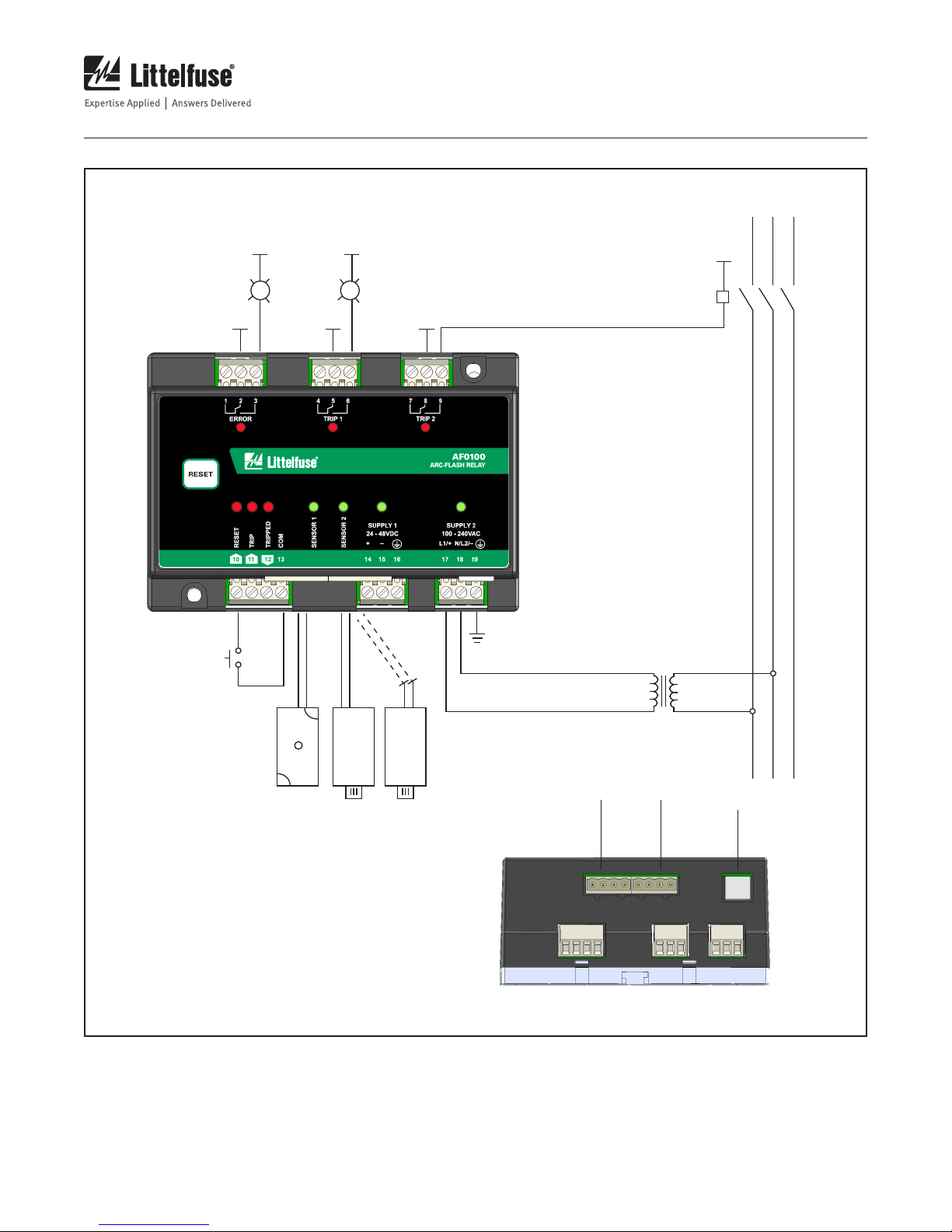
PGA-LS10
Point Sensor
NOTES:
1. RELAY OUTPUTS SHOWN DE-ENERGIZED.
2. A TOTAL OF TWO POINT OR FIBER-OPTIC SENSORS
CAN BE CONNECTED.
3. USB ‘B’ CONNECTOR. FOR CONFIGURATION, SEE
SECTION 7.3.
FIGURE 3. AF0100 Typical Wiring Diagram.
PGA-LS20/PGA-LS30
Fiber Optic Sensor
Sensor 1 Sensor 2
L1
USB
Note 3
Page 9

AF0100 Arc-Flash Relay
Page 5
REV. 0-B-013118
3 SENSOR PLACEMENT
3.1 General Guidelines
Optical sensors should have line-of-sight to points being
monitored. Ensure that the point sensors and fiber are not
blocked by fixed or moveable objects. Areas that will be
accessed for maintenance or with moveable parts (such
as draw-out circuit breakers) should be considered a high
priority for installation. Do not place sensors or cables on
bare components that will be energized and avoid sharp
bends in the cable, particularly when using the PGA-LS20
and PGA-LS30 fiber-optic sensors. The electrical cables and
sensors should be considered to be at ground potential when
determining electrical clearances.
Sensors should be mounted in a location that will minimize
the chance of debris or dust build-up and with easy access
for maintenance if needed. A point sensor mounted at the
top of an enclosure and facing down is optimal for reducing
dust build-up. It should be noted that most enclosures are
metallic and the reflectivity combined with the high intensity
of an arc mean that even a moderately dusty sensor will
collect adequate light.
In dusty environments, sensor cleaning should be part of a
regular maintenance schedule and can be performed using
compressed air or a dry cloth.
3.3 Transformer Protection
The AF0100 can also be used for the protection of transformers.
Two or more point sensors should be used per transformer to
monitor the primary and secondary connection terminals. For
the placement of the sensors, the same considerations apply
as for switchgear protection.
3.4 Generator Protection
The main area of concern for protecting the generator is the
conductors between the generator and the generator breaker.
A fault in this area is not protected by the generator breaker
from overcurrent or arc flash. Often, one or two sensors are
enough to monitor the breaker and bus connection back to
the generator. If other electrical equipment is installed on
the generator, it should also be considered in an arc-flash
risk assessment. When protecting the generator to a breaker
connection, it is important to disconnect all sources of energy
for the arc flash. Open the generator breaker to disconnect
from the utility or other parallel generators, and connect
to the automatic voltage regulator (AVR), emergency stop
or other control circuit to turn off the generator. The two
trip relays on the AF0100 are isolated so that the breaker
and control circuit can both be tripped using independent
voltages if necessary.
3.2 Switchgear Protection
The sensors used for arc-flash detection are optical sensors.
Line-of-sight between the points where an arc could occur
and the sensor is optimal, but the reflectivity of metallic
compartments will help in distributing the light from an arc
fault in the entire cabinet.
Often one point sensor is sufficient to monitor a complete
switchgear compartment. However, if there are large
components such as circuit breakers that cast shadows over
wider areas, more than one point sensor is required.
Page 10
AF0100 Arc-Flash Relay
Page 6
REV. 0-B-013118
4 OPTICAL SENSORS
The AF0100 has two inputs for optical arc-fault sensors.
Two sensor types are supported:
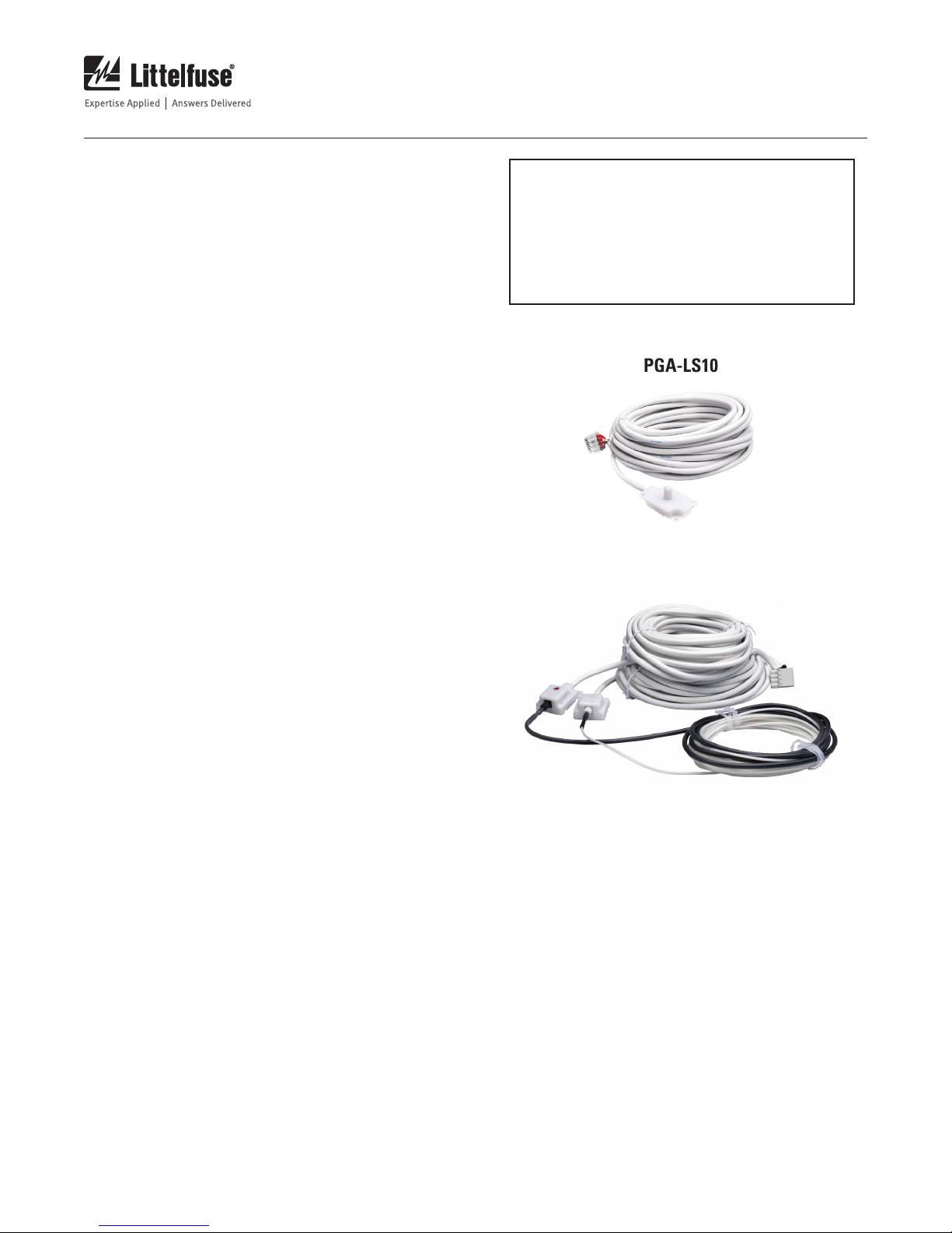
• PGA-LS10 Photoelectric Point Sensors with sensor check
• PGA-LS20 and PGA-LS30 Fiber-Optic Sensors with
sensor check
The sensors can be used together, in any combination.
Both sensor types have LED indication of sensor health and
fault location. A sensor-check circuit tests the sensor to verify
that the sensor assembly is functioning correctly. A healthy
sensor will flash its internal red LED every few seconds. A
sensor that has detected an arc will indicate solid red until
the trip is reset.
The sensors connect to the AF0100 with shielded three-wire
20 AWG (0.5 mm2) electrical cable. Each sensor includes 10 m
(33 ft) of cable which can be shortened or extended up to 50 m
(164 ft). These cables should be considered to be at ground
potential when determining electrical clearances in the
cabinet.
NOTE: Inserting and removing a sensor cable can
cause a trip, depending on which terminals make
contact first. To guard against nuisance tripping,
remove the trip coil terminal blocks before
connecting and disconnecting sensors, or perform
the maintenance while the system is de-energized.
PGA-LS10
PGA-LS20 / PGA-LS30
Any connected optical sensor with circuit check will be
automatically detected and cause the AF0100 to report an
error if it is subsequently disconnected.
Page 11
AF0100 Arc-Flash Relay
Page 7
REV. 0-B-013118
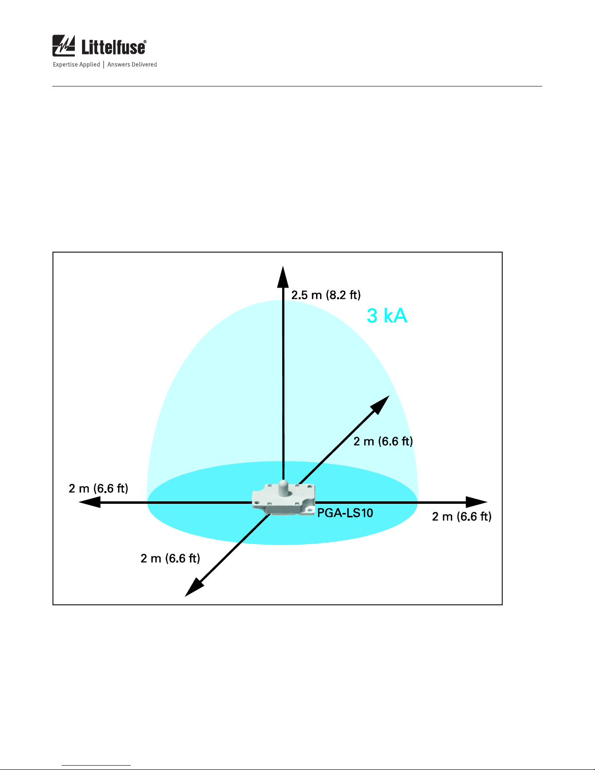
4.1 PGA-LS10 Photoelectric Point Sensor with
Sensor Check
This sensor has a detection area of a 2-m (7-ft) half-sphere
for arcs of 3 kA or more.
A built-in LED enables the AF0100 to verify the function of
the light sensor, wiring, and electronics. If the sensor does
not detect the sensor-check LED, a sensor-fail alarm will
occur – the ERROR relay will change state and the sensor
indication LED will begin to flash. See Section 7.
The sensor includes 10 m (33 ft) of shielded three-wire
electrical cable which can easily be shortened or extended to
a maximum of 50 m (164 ft). For more information on sensor
cabling, see Section 6.3.2.
FIGURE 4. PGA-LS10 Detection Range for a 3 kA Fault.
Page 12
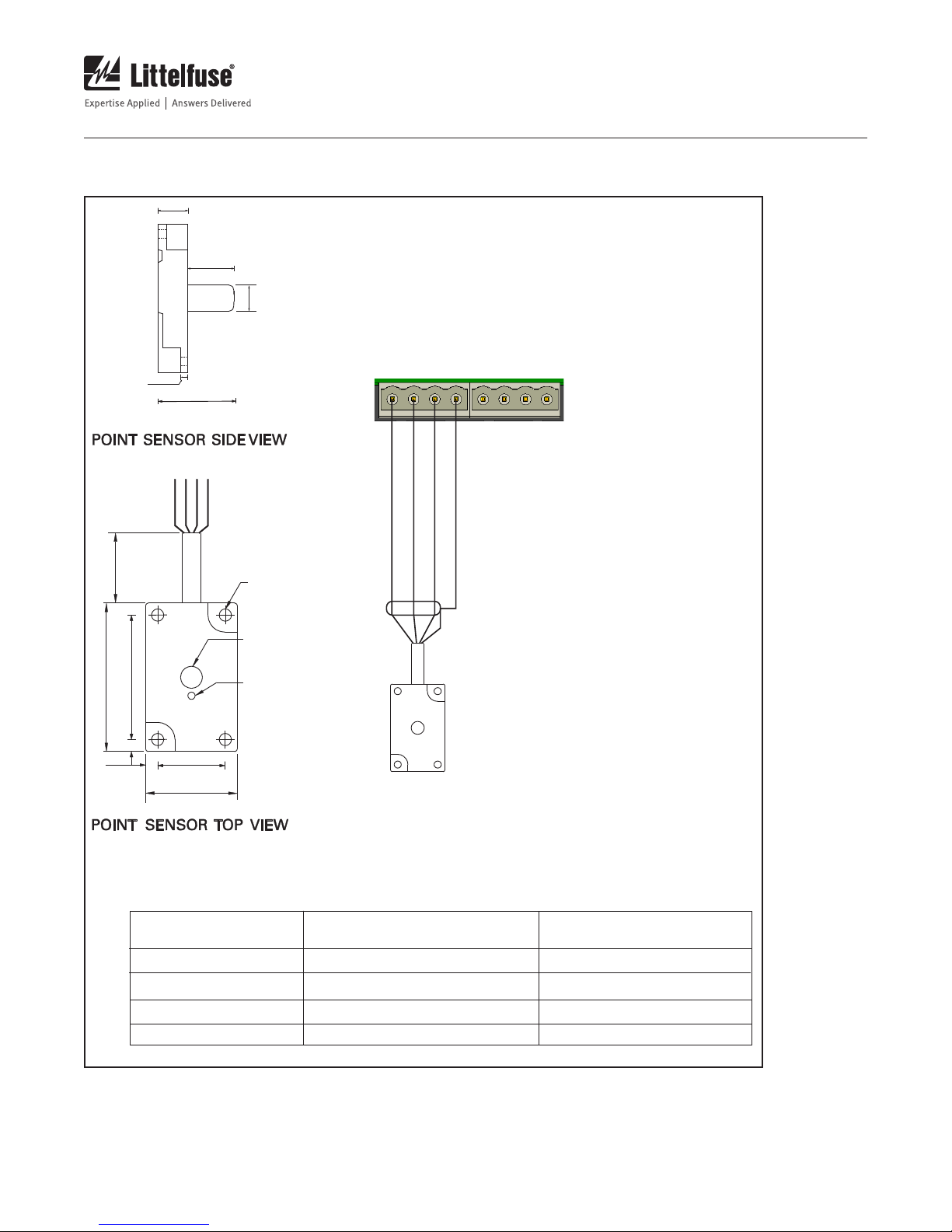
4.1.1 PGA-LS10 Connection
9.6
(0.38)
14.2
(0.56)
8.3
(0.33)
2.4
(0.09)
23.8
(0.94)
AF0100 Arc-Flash Relay
SENSOR 1 SENSOR 2
5V TX RX 0V
5V TX RX 0V
Page 8
REV. 0-B-013118
52.0
(0.16)
10 m
4.0
(32.8 ft)
44.0
(2.05)
RED
WHITE
SHIELD / BLACK
YELLOW
(1.73)
24.0
(0.94)
32.0
(1.26)
Ø4.25(0.167)
MOUNTING HOLES
Ø8.3(0.33)
SENSOR LENS
RED LED FOR
CIRCUIT CHECK AND
VISUAL DIAGNOSTICS
RED
WHITE
SHIELD / BLACK
YELLOW
NOTE 2
NOTES
1. DIMENSIONS IN MILLIMETERS (INCHES) UNLESS OTHERWISE STATED.
2. UP TO 2 PGA-LS10 PHOTOELECTRIC POINT SENSORS WITH BUILT-IN
CIRCUIT CHECK CAN BE CONNECTED.
3. THE PGA-LS10 SENSOR SHIPS ASSEMBLED WITH A PLUG-IN CONNECTOR.
IT MAY BE NECESSARY TO DISCONNECT THE PLUG-IN CONNECTOR
DURING INSTALLATION.
TERMINAL FUNCTION COLOR
5V
TX
RX
0V
SUPPLY
CIRCUIT CHECK TRANSMIT
RECEIVE
SHIELD
RED
WHITE
YELLOW
BLACK/COPPER
FIGURE 5. PGA-LS10 Connection Diagram.
Page 13

AF0100 Arc-Flash Relay
REV. 0-B-013118
4.1.2 PGA-LS10 Installation
The PGA-LS10 point sensor includes an adhesive-backed drill template for easy surface or panel-mount installation.
Page 9
FIGURE 6. PGA-LS10 Mounting Detail.
Page 14

AF0100 Arc-Flash Relay
Page 10
REV. 0-B-013118
4.2 PGA-LS20 and PGA-LS30 Fiber-Optic Sensors
with Sensor Check
The PGA-LS20 and PGA-LS30 sensors have a 360° detection
zone along the fiber’s length. A built-in LED enables the
AF0100 to verify the function of the light sensor, wiring, and
electronics. If the sensor does not detect the sensor-check
LED, a sensor-fail alarm will occur. The ERROR output will
change state, and both the LED on the front panel and the
indicator LED in the sensor itself will begin to flash red. See
Section 7.
The PGA-LS20 and PGA-LS30 sensors have three components:
1. A fiber-optic cable, with one end covered with a black
sleeve.
• PGA-LS20 has 8 m (26 ft) of active fiber and 2 m (7
ft) of covered fiber.
• PGA-LS30 has 18 m (59 ft) of active fiber and 2 m
(7 ft) of covered fiber.
2. A transmitter with a white enclosure and a white
thumb nut.
3. A receiver with a white enclosure, a black thumb nut,
and an adjustment screw behind an access hole.
Both the receiver and the transmitter connect to one AF0100
input using shielded three-wire electrical cable. All three
components are monitored to ensure correct operation.
4.2.1 Fiber Connection
Connect the black-sleeve-covered end to the receiver using
the black thumb nut, and the white uncovered end to the
transmitter using the white thumb nut. Ensure the fiber is
inserted completely into the transmitter and receiver and the
nuts are tightened. Pull gently on the cable to verify a secure
connection. The maximum pull strength of the fiber is 30 N
(6.7 lbf).
The fiber should not be sharply bent or pinched. The minimum
bending radius is 5 cm (2 in). Ensure that any drilled holes
are free of any sharp edges or burrs. Use grommets for
further protection.
NOTE: Removing the fiber from the transmitter
can cause a trip if the fiber end is pointed towards
a light source, since the fiber conducts light. This
can also happen if the receiver is pointing directly
towards a light source without a fiber connected.
To guard against nuisance tripping, remove the
trip coil terminal blocks before connecting and
disconnecting sensors and fibers, or perform the
maintenance while the system is de-energized.
4.2.2 Receiver Wiring Connections
Connect the red wire to 5V.
Connect the yellow wire to RX.
Connect the white wire and the shield to 0V.
The fiber is the light-collecting element of the PGA-LS20
and PGA-LS30. It must be installed so it has line-of-sight
to all current-carrying parts. In some cases this may be
accomplished by following the bus bars along the back wall
of the cabinets.
Drill holes using the included drill template and fasten the
transmitter and receiver to the cabinet walls using rivets or
screws. Connect the attached cables to the AF0100. The
wires of the transmitter and receiver must be connected as
shown in Fig. 7.
4.2.3 Transmitter Wiring Connections
Connect the red wire to 5V.
Connect the white wire to TX.
Connect the shield to 0V.
The yellow wire is not used.
Page 15

AF0100 Arc-Flash Relay
Page 11
REV. 0-B-013118
4.2.4 PGA-LS20 and PGA-LS30 Connection
The sensor is shipped with the wires mounted in a terminal
block. See Fig 7.
The transmitter and receiver include 10 m (33 ft) of shielded
three-wire electrical cable which can be shortened or
extended up to 50 m (164 ft). Transmitter and receiver cables
can be different lengths and must be independently shielded.
SENSOR 1 SENSOR 2
5V TX RX 0V
RED
SHIELD / BLACK
WHITE
RED
5V TX RX 0V
SHIELD / BLACK
YELLOW
WHITE
Failure to independently shield transmitter and receiver
cables can lead to an incorrect circuit check – a faulty sensor
could be falsely detected as continuous. However, if there is
no sensor fault, arc-flash detection will function normally in
this condition. For more information on sensor cabling, see
Section 6.3.2.
2.0
(0.08)
46.0
(1.81)
18.8
(0.74)
(PGA-LS20: 8 m, 26.2 ft)
(PGA-LS30: 18 m, 59 ft)
FIBER
BLACK SLEEVE
(PGA-LS20: 2 m, 6.5 ft)
(PGA-LS30: 2 m, 6.5 ft)
NOTES
1. DIMENSIONS IN MILLIMETERS (INCHES) UNLESS OTHERWISE
STATED.
2. UP TO 2 PGA-LS20 / PGA-LS30 FIBER-OPTIC SENSORS
WITH BUILT-IN CIRCUIT CHECK CAN BE CONNECTED.
3. THE PGA-LS20 AND PGA-LS30 SENSORS SHIP
ASSEMBLED WITH A PLUG-IN CONNECTOR. IT MAY BE NECESSARY
TO DISCONNECT THE PLUG-IN CONNECTOR DURING INSTALLATION.
TERMINAL FUNCTION COLOR
5V
SUPPLY (TRANSMITTER AND
RECEIVER)
TX
RX
0V
SENSOR CHECK (TRANSMITTER)
SIGNAL (RECEIVER)
SENSOR CHECK (RECEIVER) AND
BOTH SHIELDS
46.0
(1.81)
4.0
(0.16)
42.0
4.0
(0.16)
(1.65)
32.0
(1.26)
24.0
(0.94)
Ø4.25(0.167)
MOUNTING HOLES
RECEIVER
SENSITIVITY
ADJUSTMENT
SCREW
DECREASE
SENSITIVITY
THUMB NUT
RED
WHITE
YELLOW
BLACK/COPPER
FIGURE 7. PGA-LS20 and PGA-LS30 Connection Diagram.
Page 16

AF0100 Arc-Flash Relay
Page 12
REV. 0-B-013118
4.2.5 Fiber-Optic Sensor Adjustment
The sensor is calibrated at the factory for 60 cm (24 in) of fiber
in each monitored compartment. When using a fiber-optic
sensor in compartments with less than 60 cm (24 in) of fiber,
the sensitivity may have to be adjusted. The sensor is unable
to differentiate between 10,000 lux on 60 cm (24 in) of fiber
and 30,000 lux on 20 cm (8 in) of fiber – the same amount
of light is transmitted through the fiber to the receiver. To
achieve the desired sensitivity, the receiver (with the black
thumb nut) must be adjusted.
4.2.6 Sensor Adjustment For a Fiber Length Other
Than 60 cm (24 in)
To adjust the fiber length, a powerful light source of at least
100 lumen (e.g. 500 W halogen lamp) and a spare point
sensor is required. Use the following procedure to calibrate
the sensor:
1. Remove the trip coil connector to avoid tripping the
circuit breaker while testing.
2. Use a point sensor to find the distance to the lamp
at which the sensor just trips. Note the distance
between the lamp and the point sensor (typically
15-40 cm (5.9-15.7 in), depending on the lamp).
3. Adjust the receiver (black thumb nut) sensitivity
level to the minimum by turning the small metal
screw clockwise until it begins to click. This may be
too low to detect the sensor-check signal and may
cause the related LED on the relay to flash red to
signal the error. This has no implication for the rest
of the procedure, since the trip signal is transmitted
anyway.
4. Place the lamp facing the fiber in the compartment
closest to the transmitter end (white thumb nut) of
the fiber. This allows for loss along the full length
of the fiber. The distance between the lamp and the
fiber should be the same as the distance observed
in step 2.
5. Slowly turn the metal screw on the receiver counterclockwise until the AF0100 sensor-indicator LED for
that sensor changes to red, indicating a trip.
6. Press reset on the relay, and check that the sensor
indicator LED turns green, indicating that the
sensor-check signal is detected, and that the fiber
is thus protected by circuit check.
If the system compartment is very small, it may not be
possible to adjust the fiber to provide sufficient sensitivity.
Contact Littelfuse for support.
Page 17

AF0100 Arc-Flash Relay
5 APPLICATION EXAMPLES
5.1 Basic scenario: One Sensor – One Circuit Breaker
No configuration necessary.
Page 13
REV. 0-B-013118
AF010 0
Trip 1
Sensor
1 or 2
+24
Circuit
Breaker
Sensor
Incoming
FIGURE 8. Basic AF0100 Configuration.
Page 18

AF0100 Arc-Flash Relay
Page 14
REV. 0-B-013118
5.2 Total Clearing Time
The AF0100 is capable of tripping a circuit breaker in less
than 5 ms (typical) from when light hits the sensor. This is not
the same as the clearing time for the fault. The arc fault will
continue until the current to the fault has stopped flowing,
which happens when the circuit breaker connected to the
unit has reacted.
5.2.1 Arc-Detection Delay
The AF0100’s default arc-flash detection intentional delay
time is 1 ms, but can be configured between 0 and 10 ms via
the USB configuration software.
The total operating time will be the intentional delay plus the
relay operating time based on wiring and configuration. The
AF0100 operating times with no intentional delay are shown
below.
OPERATING MODE
Shunt
(Non-fail-safe)
Undervoltage
(Fail-safe)
CONTACT
CONFIGURATION
N.O.
(Normally Open)
N.C.
(Normally Closed)
N.O.
(Normally Open)
N.C.
(Normally Closed)
TRIP TIME
< 5 ms
< 3 ms
< 3 ms
< 8 ms
The total clearing time is:
Total Clearing Time = Arc-Detection Delay + Local Circuit
Breaker Operating Time
With the AF0100, the dominating time by far is the circuit
breaker operating time.
5.2.3 Total Clearing Time Examples
Example: Total Clearing Time with a 3-cycle circuit
breaker
A 3-cycle circuit breaker at 50 Hz tripping due to light on an
AF0100 sensor will have a total clearing time of:
5 + 60 = 65 ms
It is possible to reduce the total clearing time by installing
special devices, which shunt the current away from the arc
fault. These can be found with clearing times down to 1-2
ms, reducing the total clearing time down to less than 7 ms.
5.2.2 Circuit Breaker Operating Time
Circuit breakers have a predetermined operating time,
dependent on the type of circuit breaker. Older circuit breakers
have clearing times up to eight cycles, while modern circuit
breakers are able to open in one to five cycles. Refer to the
specifications of the installed circuit breaker.
TABLE 1. CIRCUIT BREAKER OPERATING TIME.
CIRCUIT BREAKER OPERATING TIME 50 HZ 60 HZ
8 cycles 160 ms 133 ms
5 cycles 100 ms 83 ms
3 cycles 60 ms 50 ms
2 cycles 40 ms 33 ms
1½ cycles 30 ms 25 ms
1 cycle 20 ms 17 ms
Page 19

AF0100 Arc-Flash Relay
TOP
2 MOUNTING HOLES
TOP
REVISION
NO.BYDATE
JR
0
INITIAL RELEASE
127.6
5.03
95.2
3.75
76.6
3.02
16.2
0.64
16.2
0.64
6.3
0.25
6.3
0.25
89.2
3.51
FRONT
TOP
PURCHASER
PROJECT IDENT.
PURCHASE ORDER NO.
EQUIPMENT NO.
REFERENCE DWG. NO.
REVISION
NO.BYDATE
JR
0
INITIAL RELEASE
Confidential and Proprietary
The information and know-how shown in this drawing are the property of Littelfuse Startco
and may not be copied or reproduced without the written permission of Littelfuse Startco nor
may they be used in any manner directly
or indirectly detrimental to the interest of Littelfuse Startco.
127.6
5.03
2 MOUNTING HOLES
5.2
0.20
95.2
3.75
76.6
3.02
16.2
0.64
16.2
0.64
6.3
0.25
6.3
0.25
89.2
3.51
FRONT
BOTTOM
35.3
1.39
59.8
2.36
SIDE
TOP
NOTES:
DIMENSIONS IN MILLIMETERS [INCHES].
1.
MOUNT USING DIN RAIL OR TWO #6 SCREWS
2.
PURCHASER
PROJECT IDENT.
PURCHASE ORDER NO.
EQUIPMENT NO.
REFERENCE DWG. NO.
DES D.
DWN.
PROJECT NO.
REVISION
INITIAL RELEASE
The information and know-how shown in this drawing are the property of Littelfuse Startco
and may not be copied or reproduced without the written permission of Littelfuse Startco nor
or indirectly detrimental to the interest of Littelfuse Startco.
127.6
5.03
2 MOUNTING HOLES
5.2
0.20
95.2
3.75
76.6
3.02
16.2
0.64
16.2
0.64
6.3
0.25
89.2
3.51
FRONT
TOP
Page 15
REV. 0-B-013118
6 INSTALLATION AND TERMINALS
The AF0100 can be surface mounted using two #6 screws
(19mm or longer), or it can be DIN-rail mounted.
NOTES:
DIMENSIONS IN MILLIMETERS [INCHES].
1.
MOUNT USING DIN RAIL OR TWO #6 SCREWS
2.
59.8
2.36
35.3
1.39
Ensure there is enough clearance around the module to allow
the plug-in terminals to be removed and inserted.
Do not install modules which have been damaged in transport.
TOP
127.6
5.03
16.2
0.64
95.2
3.75
16.2
0.64
6.3
76.6
0.25
3.02
89.2
3.51
SIDE
89.2
3.51
6.3
76.6
6.3
0.25
3.02
0.25
16.2
0.64
127.6
5.03
95.2
3.75
MOUNTING DETAIL
FIGURE 9. AF0100 Outline and Mounting Details.
16.2
0.64
5.2
0.20
FRONT
BOTTOM
6.3
0.25
Page 20

AF0100 Arc-Flash Relay
Page 16
REV. 0-B-013118
6.1 Power Supply
The AF0100 Arc-Flash Relay can be supplied by either a high
voltage ac or dc supply, an auxiliary low voltage supply, or
both.
6.1.1 Line AC Supply (optional)
Connect an ac supply to terminals 17 and 18. The supply
voltage must be 100 to 240 Vac.
6.1.2 Station Battery DC Supply (optional)
6.1.3 Auxiliary DC Supply
Connect a dc supply to terminals 14 and 15, ensuring correct
polarity. The supply voltage must be 24 to 48 Vdc.
6.1.4 Supply Surveillance
The AF0100 will automatically learn which supplies to
expect, and will indicate an error if one of the supplies is
missing or out of nominal range. This is useful to make sure
that a failure in a redundant supply is detected.
Connect a dc supply to terminals 17 and 18. The supply
voltage must be 100 to 240 Vdc.
The error will auto-reset when the supply is re-established or
can be cleared by holding the RESET button for 20 seconds.
This will redetect any connected sensors and power supplies.
See Section 7.1 for more information on the RESET button.
Page 21

AF0100 Arc-Flash Relay
Page 17
REV. 0-B-013118
6.2 Inputs and Outputs
An LED provides visual indication of each input and output
status. The output contacts are shown on the front panel in
the de-energized state.
6.2.1 ERROR Signal Relay
The ERROR output signals the health of the arc-flash relay
and its connected sensors and supplies.
The ERROR output consists of an insulated electromechanical
change-over contact (Form C / SPDT) on terminals 1, 2, and
3. In the fail-safe mode, the ERROR relay will be energized
when there are no alarms. The ERROR relay mode can
be configured with the USB configuration software.
See Section 7.3
If an error is currently active and an additional error occurs,
the ERROR output will briefly change state. This is to
communicate to connected equipment the error state has
changed, but there are outstanding errors.
If possible, an LED on the front panel will indicate where
the error is by flashing. Otherwise, the USB configuration
software will show an overview of the current errors.
The ERROR relays of several units can be combined into
one fail-safe signal by daisy-chaining terminals 2 and 3 (all
ERROR relays must be configured for fail-safe mode). In that
way, if just one of the linked units experiences an error, the
connection between the ends will be broken. Likewise, if the
wire breaks, an alarm will be raised.
6.3 Sensors
Two optical sensors can be used with the AF0100. Sensor
locations are identified as SENSOR 1 or SENSOR 2 on the top
of the AF0100. See Section 4.
6.3.1 Light Immunity Adjustment
By default, the sensors will signal an arc-fault event if the
light intensity is above approximately 10 klux. The light
intensity from an arc fault is very high, typically in the area
of 1 Mlux, and the choice of 10 klux is mostly a compromise
between being sufficiently above normal light levels (about 1
klux in a very well lit office environment) and the need to be
able to test the system with a manageable light source such
as a flashlight.
The immunity level can be changed up to 25 klux via the
USB configuration software. For information on using the
USB configuration software, see Section 7.3.
This may be required for applications with powerful work
lights or regulation requirements for the trip level.
The light sensors are not usable outdoors or in direct
sunlight, as the intensity of direct sunlight will saturate the
sensors.
6.3.2 Extending or Shortening Cable Length
Both point and fiber sensors are delivered with 10 m (33 ft) of
three-wire shielded cable. If the installation requires it, these
cables can be shortened or extended up to 50 m (164 ft). See
Sections 4.1 and 4.2.4. Use Belden 85240 or equivalent cable
(wire colors may vary).
Do not combine several sensor cables within the same
shield. Do not combine the cables to transmitter and
receiver for the fiber sensors within the same shield.
Page 22

AF0100 Arc-Flash Relay
Page 18
REV. 0-B-013118
7 USER INTERFACE
7.1 Reset Button
The RESET button on the front panel of the AF0100 has two
functions: A momentary press will reset any trip events or
errors, and holding the button will initiate additional reset
functions as described below.
Pressing the reset button will reset trip indications and
error indications for any existing error. The error indication
will remain if the error is still present and cannot be reset,
e.g. if a sensor is missing or a supply voltage is outside the
specification.
Holding the reset button for 10 seconds will reset the
internal drive to factory defaults. This does not affect the
configuration.
Holding the reset button for 20 seconds will redetect any
connected sensors and power supplies which will clear
the alarms. Do not do this until the reason for the alarm is
known, and has been rectified.
If password protection is enabled in the USB configuration,
resetting the list of connections is not allowed. In this case,
use the USB configuration software to reset the alarm.
7.2 LED Indication and Relay Operation
Input LED’s follow the input state. Since the TRIPPED digital
output is pulsed, its LED will indicate if the output has been
activated since the last reset. Blinking LED’s on the front
panel indicate errors e.g. an expected sensor is missing, etc.
To reset the expected state, use the RESET button.
SUPPLY 1 and 2 (Terminals 14 to 16 and 17 to 19,
respectively)
On, green Supply voltage is connected.
Flashing green Supply voltage on this terminal has
previously been detected, but is now
missing, or the connected supply is
outside the specifications.
Off Supply voltage is not connected.
ERROR Relay (Terminals 1 to 3)
On, red An error has been detected, and the
ERROR relay has been de-energized
(fail-safe mode) or energized (nonfail-safe mode). If another LED
is flashing, use this to localize the
error and correct the problem. The USB
configuration software can also be used to
show the cause for any standing alarm,
see section 7.3.
Off No errors detected.
The LED will not always follow the internal contacts. The
ERROR relay will be in the state shown on the front panel
when power is not connected.
In the fail-safe mode, the ERROR relay will energize if no
errors are detected, and will de-energize on errors, or if
power is removed.
In the non-fail-safe mode, the ERROR relay will de-energize
if no errors are detected or if power is removed, and will
energize on errors.
The ERROR relay will also pulse for one second if an additional
error is detected while errors are already present.
Page 23

AF0100 Arc-Flash Relay
Page 19
REV. 0-B-013118
TRIP 1 and TRIP 2 (Terminals 4 to 6 and 7 to 9,
respectively)
On, red A TRIP output is or has been active due
to an arc-flash event. Press RESET to
clear the trip.
Off No unacknowledged trips.
The LED will not always follow the status of the internal
contacts. The trip relays are shown on the front panel in their
de-energized state.
In the fail-safe mode, trip relays will energize when not in a
tripped state, and will de-energize when in a tripped sate, or
if power is removed.
In the non-fail-safe mode, the trip relays will de-energize
when not in a tripped sate, or if power is removed, and will
energize when in a tripped state.
RESET Input (Terminal 10)
On, red RESET input or another reset source
(RESET button) is active.
Off RESET input is inactive.
If the RESET input is permanently activated, errors and trips
will be reset as soon as they are cleared or completed.
TRIP Input (Terminal 11)
Sensors
On, green The sensor input is active and has a
functional sensor connected.
On, red The sensor caused a trip event. The LED
in the sensor will also be solid red. Press
the RESET button to clear the trip.
Flashing red The circuit check of the sensor failed;
check the wiring and that fiber sensors
are fully seated in the thumb screws. If
possible, the LED in the sensor will also
be flashing red. If a sensor has been
removed temporarily or on purpose,
press and hold the RESET button for a
20 seconds to redetect any connected
sensors.
Off The input has not detected a connected
sensor. The input will by default still be
active.
PGA-LS10, PGA-LS20 and PGA-LS30
Flashing Red The sensor is operating normally.
On, red (brief
flashing red
every 2 s) The sensor caused a trip event.
On, red TRIP input is active.
Off TRIP input is inactive.
TRIPPED Output (Terminal 12)
On, red The TRIPPED output is or has been
active. Press RESET to clear the trip.
Off The TRIPPED output is inactive.
Off The sensor is unplugged or faulty, or
the AF0100 is without power (check the
wiring and that fiber sensors are fully
seated in the thumb screws).
Page 24

AF0100 Arc-Flash Relay
Page 20
REV. 0-B-013118
7.3 USB Conguration Software
To access the configuration software, plug in a USB connector
and connect to a Windows1 computer.
After a few seconds, the following will appear:
Open the Configuration drive, and double click on the file
named ’config.hta’
The configuration software will now open.
Tabs show each logical section of the relay.
Hovering above each setting will display the valid limits for
the setting.
Press the Save button and remove the USB connector to
apply the new configuration.
NOTE:
1
All Microsoft Windows versions from and including
Windows XP are supported. Some corporate networks may
disallow HTA applications, in which case you should contact
your system administrator to allow local HTA files to run.
Page 25

AF0100 Arc-Flash Relay
Page 21
REV. 0-B-013118
It is not possible to view live data from the unit via USB.
The values shown for e.g. sensor state are the values at
the moment the USB connector was plugged in. Setting the
7.3.1 USB Conguration Software – Screen Examples
password in the USB configuration software will prevent
the list of connected devices from being reset via the reset
button on the front panel.
Page 26

AF0100 Arc-Flash Relay
Page 22
REV. 0-B-013118
Page 27

AF0100 Arc-Flash Relay
The USB configuration software also shows the cause of any standing alarms in clear text.
Page 23
REV. 0-B-013118
Page 28

AF0100 Arc-Flash Relay
Page 24
REV. 0-B-013118
7.4 Firmware Upgrade
NOTE: The AF0100 will restart during the firmware
upgrade process. The TRIP and ERROR relays may
change state. Ensure the equipment is in a safe
state prior to starting the upgrade process. Do not
interrupt the firmware upgrade process.
NOTE: The redundant trip circuit is active during
the firmware upgrade process, but will operate
in a shunt-trip mode only. Once the firmware
upgrade process has completed,normal operation
will continue as previously configured via the
configuration software. See Appendix B for more
information.
Product information, including hardware and firmware details,
can be reviewed in the About tab as shown in Section 7.3.1.
Follow the procedure below to perform a firmware upgrade:
1. Contact Littelfuse at relays@littelfuse.com to obtain the
newest firmware file.
4. Disconnect the USB cable. The firmware upgrade will
begin. Progress will be shown on the front panel as
outlined below. The firmware upgrade can take up to five
minutes.
TABLE 2. AF0100 FIRMWARE UPGRADE SEQUENCE.
Sensor 1 Sensor 2 Description
Sensor 2 flashing
Sensor 1 flashing
Sensor 1 ON,
Sensor 2 flashing
Sensor 1 flashing,
Sensor 2 ON
Unit reset AF0100 will reset
Sensor 1 and 2 flashing green for
3 seconds – Upgrade passed
or
Sensor 1 and 2 flashing red for
3 seconds – Upgrade failed
2. Connect the AF0100 to a computer using a USB cable.
See Section 7.3.
3. Copy the AF0100.bin and AF0100.md5 files to the AF0100
Configuration drive.
Unit reset AF0100 will reset
Firmware upgrade process complete.
Legend:
OFF FLASHING ON
5. The AF0100 will restart twice when the firmware
upgrade has been completed.
6. Close the Configuration Software screen (HTA file).
7. Reconnect the AF0100 to the computer as in Step 2.
8. Confirm that the firmware revision shown in the About
tab is correct.
Page 29

AF0100 Arc-Flash Relay
Page 25
REV. 0-B-013118
8 COMMISSIONING
With no manual configuration, a freshly unpacked and wired
AF0100 will work using the factory default settings. It will
trip the TRIP 1 and TRIP 2 outputs if light applied to any
sensors connected to SENSOR 1 or SENSOR 2 exceeds the
default setting of 10 klux, even if a circuit check is reporting
a cable to be broken.
The digital I/O (TRIP and RESET inputs, TRIPPED output) will
also be enabled.
Littelfuse recommends always doing a full system test on all
sensors and outputs to ensure that any errors in the cabling
or configuration will be detected and can be corrected before
the system is put into normal operation.
CAUTION: Make sure that the area is safe before this
test. Ensure that loads and power are disconnected at
the transformers, etc.
8.1 Conguration of Installed Sensors
The AF0100 will auto-detect sensors as they are connected.
To reset any errors (shown as blinking red LED in a position
where no sensor is attached), e.g. after moving a sensor to
another position on the unit, press and hold the RESET button
for 20 seconds. This will redetect any connected sensors and
power supplies.
8.2 Testing the Sensors
To test the tripping of point sensors, the intensity of light
at the sensors needs to rise above 10 klux (or the defined
light immunity setting, if changed). The LED flash on most
phones are not sufficient, nor are most LED flashlights. Most
incandescent flashlights (e.g. Mini Maglite with Xenon bulb
or larger) can be used, if the beam can be focused to a very
small circle and the flashlight is brought right next to the
sensor. A normal AC light bulb can also be used.
For fiber sensors, the light intensity needs to be above 10 klux
on a much larger area, which is not possible with a flashlight
or standard light bulbs. To test fiber sensors, a 300-500 W
halogen lamp or a powerful photo flash with a guide number
of at least 15 m (50 ft) is needed. See Section 10.7.
1. Unplug the TRIP outputs to avoid tripping the circuit
breakers. If the AF0100 output is connected to other
devices, disconnect these connectors as well.
2. Confirm that there is a solid green LED for each
connected optical sensor. This confirms that sensors
are connected and healthy.
3. Confirm that a short red flashing light occurs
periodically in each sensor. This indicates that the
sensor circuit is being checked.
4. Point the light source at a sensor and check that
the LED on the sensor and the front panel of the
AF0100 turns red continuously. The TRIPPED LED
will also turn on. If this does not happen, the light
source may not be powerful enough, especially for
fiber sensors.
5. Repeat for the remaining sensors.
6. Check that the indicator LED’s on the front panel of
the unit have turned red for all connected sensors.
7. Press the RESET button to clear the trip indication.
Replace any connectors removed to re-establish protection.
Page 30

AF0100 Arc-Flash Relay
Page 26
REV. 0-B-013118
8.3 Testing the TRIP 1 and TRIP 2 Outputs and
Associated Circuit Breakers
To ensure the system is ready to test, the system should
only have supply power. The TRIP 1 and TRIP 2 outputs will
be tripped during this procedure. Also be aware that other
devices connected to the trip outputs will also trip, unless
the connection is removed for the test.
1. Reset the AF0100. Ensure there are no trips or
errors present.
2. Connect the TRIP input to COM using a piece of
wire, terminals 11 to 13.
3. Observe that the connected trip coil operates.
4. Press the RESET button to reset the trip indication.
Reset the tripping device if necessary.
5. Replace any connectors removed to re-establish
protection.
6. Repeat for each TRIP 1 and TRIP 2 output.
8.4 Full Operation Test
2. Make a table with a row for each sensor, and mark
which circuit breakers should trip in order to remove
power completely from the area. See Table 2.
3. Confirm that there is a solid green LED for each
connected optical sensor. This confirms that sensors
are connected and healthy.
4. Confirm that a short red flashing light occurs
periodically in each sensor. This indicates that the
sensor circuit is being checked.
5. Move a light source towards the sensor. Confirm
that the TRIP1 and TRIP 2 outputs trip and that the
LED’s of the TRIP outputs and sensor change to red.
Confirm that all circuit breakers which supply the
area which the sensor can see have tripped. Note
the result in the table.
6. Press RESET on all affected units, and reset the
tripping device if necessary.
7. Repeat steps 3 to 6 for the remaining sensors.
To ensure the system is ready to test, the system should only
have supply power. The TRIP outputs will change state during
this procedure.
1. Use the system diagram to find out which circuit
breakers should trip for each sensor. Generally, the
system should be set up so that light on a sensor
removes power from any conductor that the sensor
can see.
TABLE 3. SAMPLE TABLE FOR TESTING A SYSTEM.
SENSOR: SHOULD TRIP THESE CIRCUIT BREAKERS: OBSERVED TRIPS:
Unit 1, sensor 1
Placed on Busbar
Unit 1, sensor 2
Placed in Circuit Breaker 2 Cabinet
Unit 2, sensor 1
Placed in Circuit Breaker 3 Cabinet
Etc.
Incoming Circuit Breaker 1
Incoming Circuit Breaker 1
Circuit Breaker 2
Page 31

AF0100 Arc-Flash Relay
Page 27
REV. 0-B-013118
9 SUPPORT RESOURCES
The most up-to-date manuals, data sheets, instruction
videos, etc. can be found on the AF0100 site at
www.littelfuse.com/AF0100.
The AF0100 is supported through the Littelfuse network of
technical sales and distributors. For installation help and
support, please contact your sales representative. Include
detailed information about the installation and application.
See Section 2.
9.1 Sending Information For Support
A picture or video of the installation makes it much easier to
provide assistance. Also, the configuration and log files can
be very helpful, as is the serial number of the unit.
Attaching the files to the support email can be done as
follows:
Plug in a USB connector and connect to a computer.
After a few seconds, one new drive appears.
From the CFG drive, select and attach the CONFIG.CFG,
AF0100.LOG, and AF0100.TXT files.
Provide a single line diagram of the installation if possible.
Page 32

AF0100 Arc-Flash Relay
Page 28
REV. 0-B-013118
10 SPECIFICATIONS
10.1 AF0100
Supply:
Supply 1:................. .................... 4 W, 24 to 48 Vdc
(+10%, -25%)
Supply 2:... ................ ................. 10 VA, 100 to 240 Vac
AF0100-00 only
Optical Settings:
External Sensors: .......................2 Light sensors
Sensor Types: .............................PGA-LS10, PGA-LS20, and
PGA-LS30, all with sensor
Immunity
Adjustment: ...............................Trip above 10 to 25 klux
Intentional Trip
Delay Settings: .......................... 0 to 10 ms
TRIP 1 and TRIP 2 Outputs:
Configuration: ............................ Change-over (Form C)
UL Rating ................................... 6 A resistive 240 Vac,
Supplemental Ratings:
Make/Carry 0.2 s: ...............30 A
Rating Code: .......................B300, R300
Minimum Switching Load ...100 mA, 5 Vdc
Maximum Switching
Capacity...............................Fig. 17
Break:
dc: ..................................28 W Resistive
ac: .................................1500 VA (PF=1.0)
360 VA (PF=0.4)
Subject to maximums of
Operating Mode: ....... ................ . Shunt trip (non-fail-safe)
(+10%, -20%) 50/60 Hz,
5 W, 100 to 250 Vdc
(+10%, -20%)
check
0 ms intentional delay
results in a maximum 0.8
ms total delay (plus relay
operate time)
isolated contact
6 A resistive 30 Vdc
6 A and 250 V (ac or dc)
or undervoltage trip
(fail-safe), independently
configurable
Isolation:.....................................1,600 Vac
Trip Time (with 0 ms intentional delay):
Mode:
Shunt Trip (non-fail-safe):
Normally open contact:
.......<
Normally closed contact:
....
5 ms
.< 3 ms
Undervoltage Trip (fail-safe):
Normally open contact:
......
Normally closed contact:
.< 3 ms
.....<
8 ms
Error Output:
Configuration:
............................. Change-over (Form C)
isolated contact
UL Rating: .................................. 6 A resistive 240 Vac,
6 A resistive 30 Vdc
Supplemental Ratings:
Make/Carry 0.2 s................30 A
Rating Code: .......................B300, R300
Minimum Switching Load ..100 mA, 5 Vdc
Maximum Switching
Capacity...............................Fig. 17
Break:
dc:.................................28 W Resistive
ac:................................ 1500 VA (PF=1.0)
360 VA (PF=0.4)
Subject to maximums of 6
A and 250 V (ac or dc)
Operating Mode: ........ ................Fail-Safe or Non-Fail-Safe
Isolation: ....................................1,600 Vac
Redundant Circuit Trip Time.............. 10 ms max,
Shunt Trip Operation Only
See Appendix B.
Terminals............................... ............Wire Clamping, 22-12
AWG (0.14 to 2.5 mm2)
copper conductors
Torque:................................ .... ...........7 lbf∙in (0.79 N∙m)
Local Interface: ................................. USB 2.0 Full speed Mass
storage device
Dimensions:
Height: ................................90 mm (3.5 in)
Width: ................................128 mm (5.0 in)
Depth: .................................60 mm (2.4 in)
Shipping Weight: ..............................0.9 kg (2 lb)
Page 33

AF0100 Arc-Flash Relay
Page 29
REV. 0-B-013118
Mounting: .......................................... 35 mm DIN rail or
surface mount
Environment:
Operating Temperature:
............... -40 to 70°C
(-40 to 158°F)
Storage Temperature: ................ -40 to 70°C
(-40 to 158°F)
Humidity: .................. ................93% Non-condensing
Enclosure Rating ........................IP20
Altitude:
Below 2,000 m (6,500 ft): ........... Normal Operation
Above 2,000 m (6,500 ft): ........... 24 Vdc supply only
Above 4,000 m (13,000 ft): ......... Contact Littelfuse
for further
information.
10.2 EMC Tests
Verification tested in accordance with EN 60255-26:2013.
Radiated and Conducted
Emissions:.......................................... CISPR 11:2009,
CISPR 22:2008,
EN 55022:2010
Class A
Current Harmonics and
Voltage Fluctuations .......................... IEC 61000-3-2
and IEC 61000-3-3
Class A
Electrostatic Discharge ..................... IEC 61000-4-2 ± 6 kV
contact discharge
(direct and indirect) ± 8
kV air discharge
Radiated RF Immunity .......... ............. IEC 61000-4-3
10 V/m, 80-1,000 MHz,
80% AM (1 kHz)
10 V/m, 1.0 to 2.7 GHz,
80% AM (1 kHz)
Fast Transient ....................... ............. IEC 61000-4-4 Zone B
± 2 kV (power supply
port), ± 1 kV (all other-
ports)
Surge Immunity ................................ IEC 61000-4-5
Zone B
± 1 kV differential mode
± 2 kV common mode
Conducted RF Immunity ....... ............ IEC 61000-4-6
10 V, 0.15-80 MHz,
80% AM (1 kHz)
Magnetic Field Immunity.................. IEC 61000-4-8
50 Hz and 60 Hz
30 A/m and 300 A/m
Power Frequency3 ............................ IEC 61000-4-16
Zone A: differential mode
100 Vrms
Zone A: common mode
300 Vrms
1 MHz Burst ..................................... IEC 61000-4-18
± 1 kV differential mode
(line-to-line)
± 2.5 kV common mode
Voltage Interruption ......................... IEC 61000-4-11,
IEC 61000-4-29
0% for 10, 20, 30,
50 ms (dc)
0% for 0.5, 1, 2.5,
5 cycles (60 Hz)
IEC 61000-4-17
Level 4, 15% of rated
dc value
Surge Withstand: .............................. ANSI/IEEE C37.90.1-2002
(Oscillatory and Fast
Transient)
10.3 Environmental Tests
Cold:.................................................. IEC 60068-2-1:2007
Test Temperature:........................-40°C
Duration:......................................16 hours
Dry Heat:...........................................IEC 60068-2-2:2007
Test Temperature:........................70°C
Duration:......................................16 hours
Humidity:......................................50% RH
Damp Heat Cyclic.............................IEC 60068-2-30:2005
Lower Temperature:
Humidity Range:..........................95 – 100 % RH
Upper Temperature:
Humidity Range:..........................90 – 96 % RH
Number of Cycles:.......................2
Vibration:
EN60225-21-1............................. Vibration, Shock, and
EN60225-21-2.............................Shock and Bump
......................25°C
......................55°C
Seismic
Page 34

AF0100 Arc-Flash Relay
Page 30
REV. 0-B-013118
10.4 Safety
Safety: ............................ IEC 61010-1: 2010 + AMD1:2016
3rd Edition
Safety Requirements for Electrical
Equipment for Measurement, Control,
and Laboratory Use – Part I
UL508 Industrial Control Equipment
10.5 Certication
Certification:
UL508 Industrial Control Equipment
Australia, Regulatory Compliance Mark (RCM)
CE, European Union
EMC directive 2014/30/EU: Certified to
IEC/EN 60255-26:2013
Low voltage directive 2014/35/EU: Certified to
IEC/EN 61010-1:2010 + AMD1:2016
1
FCC Part 15, Subpart B, Class A –
Unintentional Radiators
Page 35

AF0100 Arc-Flash Relay
10.6 Sensors
PGA-LS10 PGA-LS20 and PGA-LS30
Type: Point sensor Fiber-optic sensor
Page 31
REV. 0-B-013118
Detection Zone:
Output:
Electrical Cable:
180 x 360° (half sphere)
0-35 mA
Shielded 3-wire 20 AWG (0.5 mm2) electrical cable
360° along fiber
0-35 mA
Shielded 3-wire 20 AWG (0.5 mm2)
electrical cable
PGA-LS20:
8 m (26 ft) active;10 m (33 ft) total
(2 m (7 ft) shielded),
Factory Cable Length: 10 m (33 ft) electrical cable
2 x 10 m electrical cable
PGA-LS30:
18 m (59 ft) active; 20 m (66 ft) total
(2 m (7 ft) shielded),
2 x 10 m (33 ft) electrical cable
Max. Elec. Cable Length: 50 m (164 ft) 50 m (164 ft)
Sensor Check: Built-in LED for visual feedback Built-in LED for visual feedback
Transmitter and Receiver:
32 x 56 x 19 mm
(1.3 x 2.2 x 0.7 in)
Dimensions:
32 x 52 x 24 mm
(1.3 x 2.0 x 0.9 in)
Enclosure: IP 30 IP 30
Page 36

AF0100 Arc-Flash Relay
Page 32
REV. 0-B-013118
10.7 Ordering Information
AF0100-
Accessories:
PGA-LS10 Point Sensor
PGA-LS20 Fiber-Optic Sensor, 8 m (26 ft)
active length
PGA-LS30 Fiber-Optic Sensor, 18 m (59 ft)
active length
PGA-FLSH-00 Photo Flash for commissioning testing
PGA-FLSH-01 Photo Flash, CE and RoHS
0 -
Conformal Coating
Blank - No Conformal Coating
CC - Full Conformal Coating
Supply:
0: Dual Supply (100-240 Vac/100-250 Vdc,
24-48 Vdc)
1: Single Supply (24-48 Vdc)
10.8 Related Products
AF0500 Stand-alone Arc-Flash Relay with 4 sensor inputs,
2 trip coil outputs, 2 zones
PGR-8800 Stand-alone Arc-Flash Relay with 6 sensor inputs,
1 trip coil output, current inputs
10.9 Warranty
The AF0100 Arc-Flash Relay is warranted to be free from
defects in material and workmanship for a period of five
years from the date of purchase.
Littelfuse will (at Littelfuse’s option) repair, replace, or refund
the original purchase price of a AF0100 that is determined
by Littelfuse to be defective if it is returned to the factory,
freight prepaid, within the warranty period. This warranty
does not apply to repairs required as a result of misuse,
negligence, an accident, improper installation, tampering,
or insufficient care. Littelfuse does not warrant products
repaired or modified by non-Littelfuse personnel.
NOTES:
1. The AF0100 Arc-Flash Relay is currently listed as a
protective relay (UL category NRGU) and complies with the
UL508 Industrial Control Equipment standard. UL did not
evaluate the functionality of the arc-fault protection afforded
by this product. A file review will occur when the requirements
for investigation of arc detection and mitigation systems are
developed and additional tests will be performed if required.
2. The AF0100 uses the open source component FreeMODBUS
internally. For license, version, and source-code information
please contact opensource@littelfuse.com.
3. Remote-reset wiring is limited to 10 m (32 ft).
Page 37

10.0
Remote-Indication Relay
Maximum Switching Capacity
CURRENT, A
9.0
8.0
7.0
6.0
5.0
4.0
3.0
2.0
1.0
Page 33
AF0100 Arc-Flash Relay
REV. 0-B-013118
AC Resistive
Load
DC Resistive
Load
.9
.8
.7
.6
.5
.4
.3
.2
.
1
304050
10
20
FIGURE 10. TRIP and ERROR Relays Maximum Switching Capacity.
708090
60
100
VOLTAGE, V
200
250
300
400
500
600
700
800
900
1000
Page 38

AF0100 Arc-Flash Relay
APPENDIX A INSTALLATION LOG SHEET
GENERAL INSTALLATION SETTINGS MIN DEFAULT MAX UNIT COMMENTS
Date Installed
Operator
Comment 1
Comment 2
GENERAL
System Name
Description Of This Unit AF0100 Arc-Flash Relay
LIGHT SENSORS
Common Settings
Light Immunity Lower Limit 10 10 25 klux _________ klux
Page 34
REV. 0-B-013118
Arc Detection Time Before Tripping
Light Sensor 1
Sensor Status
Sensor Description Sensor 1
Change Configuration No Change
Light Sensor 2
Sensor Status
Sensor Description Sensor 2
Change Configuration No Change
COMMON CONTROL BLOCK
Trip Input
Enabled Enabled
Trip Output
Circuit Breaker Type
ADVANCED
Possibility To Reset Configuration And
Drive – No Setup Parameters
ALARMS
Shows Currently Standing Alarms
0
(Effective 0.8)
1 10 ms _________ ms
Shunt Coil (Trips When
Powered)
q Sensor Present
q No Sensor Detected
q Sensor Missing
q Sensor Tripped
q No Change
q No Sensor Expected
q Sensor Expected
q Sensor Present
q No Sensor Detected
q Sensor Missing
q Sensor Tripped
q No Change
q No Sensor Expected
q Sensor Expected
q Enabled q Disabled
Shunt Coil (Trips When Powered)
q Undervoltage Coil (Closed While
Powered)
Page 39

AF0100 Arc-Flash Relay
APPENDIX B REDUNDANT TRIP CIRCUIT
DESCRIPTION
The AF0100 includes a redundant trip circuit which is active
any time the CPU is not actively monitoring. Two conditions
in which the CPU is not actively monitoring are during
initialization (approximately 500ms following application of
power) and in the extremely rare event that an internal CPU
failure is detected.
When the CPU is active, it assumes control over the trip
circuitry. When the CPU is inactive or initializing the AF0100
behaves as follows:
• Light Sensor Programmed Delay – the redundant trip
circuit is hard wired and includes no delay, the
programmed sensor delay is ignored
• Trip Relay Mode – the fail-safe/non-fail-safe
setting is ignored, and trip relays operate in shunt
or non-fail-safe mode, so a trip condition causes the
trip relays to be energized
Page 35
REV. 0-B-013118
• Sensor Detection – sensor detection and failure
reporting is inactive, but light intensity is monitored
• TRIP Input – the TRIP 1 and TRIP 2 relays are
energized while the TRIP Input is active
• TRIPPED Output – the TRIPPED output is active
while light is detected or while the TRIP Input
is active
• RESET Input – the reset input is ignored
• RESET Button – the reset button is ignored
• ERROR Relay – the error relay is de-energized
• LEDs – all LEDs are off
NOTE: When under software control, the outputs
operate in their configured operating mode (shunt
trip or undervoltage trip). When controlled via redundant hardware, they are held statically as long
as the sensor reports light over the threshold, and
will operate only in the shunt trip mode.
Page 40

AF0100 Arc-Flash Relay
APPENDIX C
AF0100 REVISION HISTORY
Page 36
REV. 0-B-013118
MANUAL RELEASE
DATE
January 31, 2018 0-B-013118
December 5, 2017 0-B-120517
March 1, 2017 0-A-030117 1.00.01
MANUAL REVISION
HARDWARE REVISION
(REVISION NUMBER ON
PRODUCT LABEL)
0
MANUAL REVISION HISTORY
Revision 0-B-013118
Section 10.9
Updated warranty information.
Revision 0-B-120517
Section 10
Updated certification information.
Revision 0-A-030117
Initial release.
HARDWARE REVISION HISTORY
Hardware Revision 0
Initial release.
FIRMWARE REVISION HISTORY
Firmware Revision 1.00.02
The RESET function was corrected to properly
reset an external TRIP.
Firmware Revision 1.00.01
Initial release.
FIRMWARE REVISION
1.00.02
1.00.02
 Loading...