

Page 1
72R Series
POLYFUSE® Resettable PTCs
Radial Leaded > 72R Series
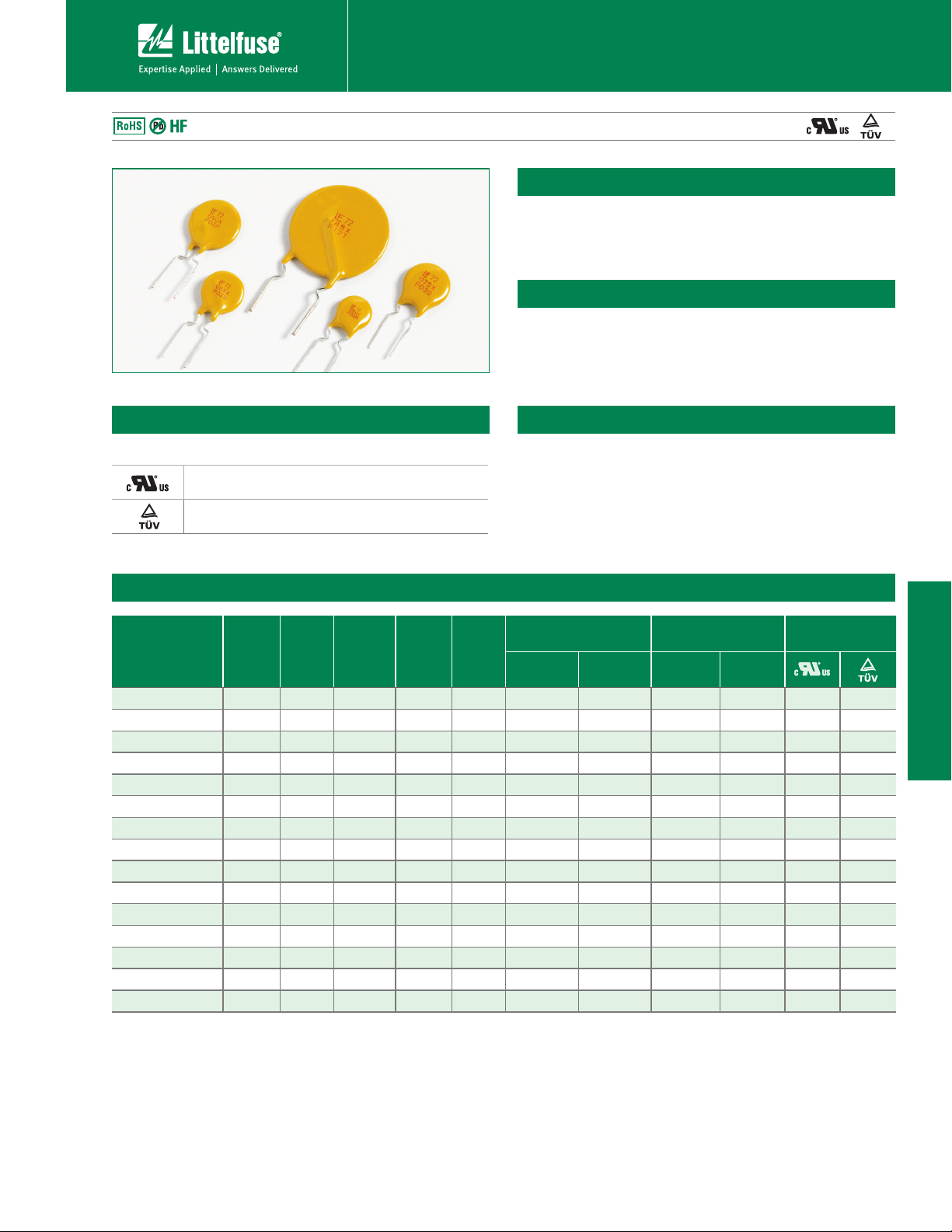
Description
The 72R Series is designed to provide overcurrent
protection to 72Vdc maximum voltage with a maximum
40A short circuit rating.
Features
t7EDNBYWPMUBHFXNBY
40A short circuit rating
t3P)4DPNQMJBOU-FBE'SFF
and Halogen Free*
Agency Approvals
AGENCY AGENCY FILE NUMBER
E183209
R50119318
Applications
t-PBEQSPUFDUJPOPOXJEF
range of low voltage power
supplies
t$PNQVUFST
Electrical Characteristics
Maximum Time
To Trip
Current
(A)
Time
(Sec.)
Part Number
I
hold
(A)
I
(A)
trip
V
max
(Vdc)
I
(A)
max
Pd
typ.
(W)
72R020X 0.20 0.40 72 40 0.41 1.00 2.20 1.830 4.400
72R025X 0.25 0.50 72 40 0.45 1.25 2.50 1.250 3.000
72R030X 0.30 0.60 72 40 0.49 1.50 3.00 0.880 2.100
72R040X 0.40 0.80 72 40 0.56 2.00 3.80 0.550 1.290
72R050X 0.50 1.00 72 40 0.77 2.50 4.00 0.500 1.170
72R065X 0.65 1.30 72 40 0.88 3.25 5.30 0.310 0.720
72R075X 0.75 1.50 72 40 0.92 3.75 6.30 0.250 0.600
72R090X 0.90 1.80 72 40 0.99 4.50 7.20 0.200 0.470
72R110X 1.10 2.20 72 40 1.50 5.50 8.20 0.150 0.380
72R135X 1.35 2.70 72 40 1.70 6.75 9.60 0.120 0.300
72R160X 1.60 3.20 72 40 1.90 8.00 11.40 0.090 0.220
72R185X 1.85 3.70 72 40 2.10 9.25 12.60 0.080 0.190
72R250X 2.50 5.00 72 40 2.50 12.50 15.60 0.050 0.130
72R300X 3.00 6.00 72 40 2.80 15.00 19.80 0.040 0.100
72R375X 3.75 7.50 72 40 3.20 18.75 24.00 0.030 0.080
Resistance
R
min
(Ω)
t3FTFUUBCMFGFBUVSF
t*EFBMGPSBCSPBESBOHFPG
general electronics using a
low voltage power supply
t$PNQVUFSQFSJQIFSBMT
t(FOFSBMFMFDUSPOJDT
Agency
Approvals
R
1max
(Ω)
XX
XX
XX
XX
XX
XX
XX
XX
XX
XX
XX
XX
XX
XX
XX
72R Series
I
= Hold current: maximum current device will pass without tripping in 23°C still air.
hold
= Trip current: minimum current at which the device will trip in 23°C still air.
I
trip
= Maximum voltage device can withstand without damage at rated current (I max)
V
max
= Maximum fault current device can withstand without damage at rated voltage (V
I
max
= Power dissipated from device when in the tripped state at 23°C still air.
P
d
= Minimum resistance of device in initial (un-soldered) state.
R
min
* Effective January 1, 2010, all 72R PTC products will be manufactured Halogen Free (HF). Existing Non-Halogen Free 72R PTC products may continue to be sold, until supplies are depleted.
© 2010 Littelfuse, Inc
Specifications are subject to change without notice.
Please refer to www.littelfuse.com/series/72R.html for current information.
)
max
Revised: July 12, 2010
= Maximum resistance of device at 23°C measured one hour after tripping or reflow
R
1max
soldering of 260°C for 20 sec.
Caution: Operation beyond the specified rating may result in damage and possible arcing
and flame.
91
72R Series
Page 2
POLYFUSE® Resettable PTCs
Radial Leaded > 72R Series
Temperature Rerating
Ambient Operation Temperature
-40°C -20°C 0°C 23°C 40°C 50°C 60°C 70°C 85°C
Part Number Hold Current (A)
72R020X 0.31 0.27 0.24 0.20 0.16 0.14 0.13 0.11 0.08
72R025X 0.39 0.34 0.30 0.25 0.20 0.18 0.16 0.14 0.10
72R030X 0.47 0.41 0.36 0.30 0.24 0.22 0.19 0.16 0.12
72R040X 0.62 0.54 0.48 0.40 0.32 0.29 0.25 0.22 0.16
72R050X 0.78 0.68 0.60 0.50 0.41 0.36 0.32 0.27 0.20
72R065X 1.01 0.88 0.77 0.65 0.53 0.47 0.41 0.35 0.26
72R075X 1.16 1.02 0.89 0.75 0.61 0.54 0.47 0.41 0.30
72R090X 1.40 1.22 1.07 0.90 0.73 0.65 0.57 0.49 0.36
72R110X 1.71 1.50 1.31 1.10 0.89 0.79 0.69 0.59 0.44
72R135X 2.09 1.84 1.61 1.35 1.09 0.97 0.85 0.73 0.54
72R160X 2.48 2.18 1.90 1.60 1.30 1.15 1.01 0.86 0.64
72R185X 2.87 2.52 2.20 1.85 1.50 1.33 1.17 1.00 0.74
72R250X 3.88 3.40 2.98 2.50 2.03 1.80 1.58 1.35 1.00
72R300X 4.65 4.08 3.57 3.00 2.43 2.16 1.89 1.62 1.20
72R375X 5.81 5.10 4.46 3.75 3.04 2.70 2.36 2.03 1.50
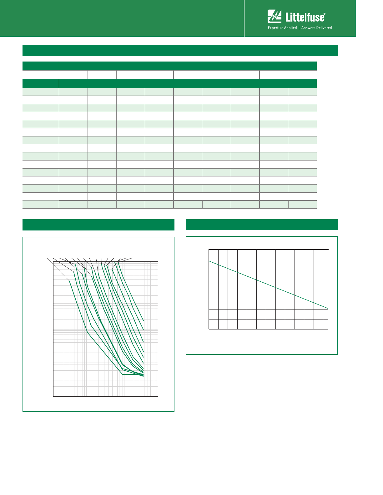
Average Time Current Curves
0.20A
0.25A
0.30A
0.40A
0.50A
0.65A
0.75A
0.90A
1.10A
100
10
1
Time in Seconds
0.1
0.01
0.1 1 10 100
Current in Amperes
1.35A
1.60A
1.85A
2.50A
3.00A
3.75A
72R
Temperature Rerating Curve
170%
150%
130%
110%
90%
70%
50%
Percentage of Rated Current
30%
10%
-40 -30 -20 -10 0 10 20 30 40 50 60 70 80
Temperature (°C)
The average time current curves and Temperature Rerating curve performance is affected
by a number or variables, and these curves provided as guidance only. Customer must
verify the performance in their application.
72R Series
Revised: July 12, 2010
92
Please refer to www.littelfuse.com/series/72R.html for current information.
Specifications are subject to change without notice.
© 2010 Littelfuse, Inc.
Page 3
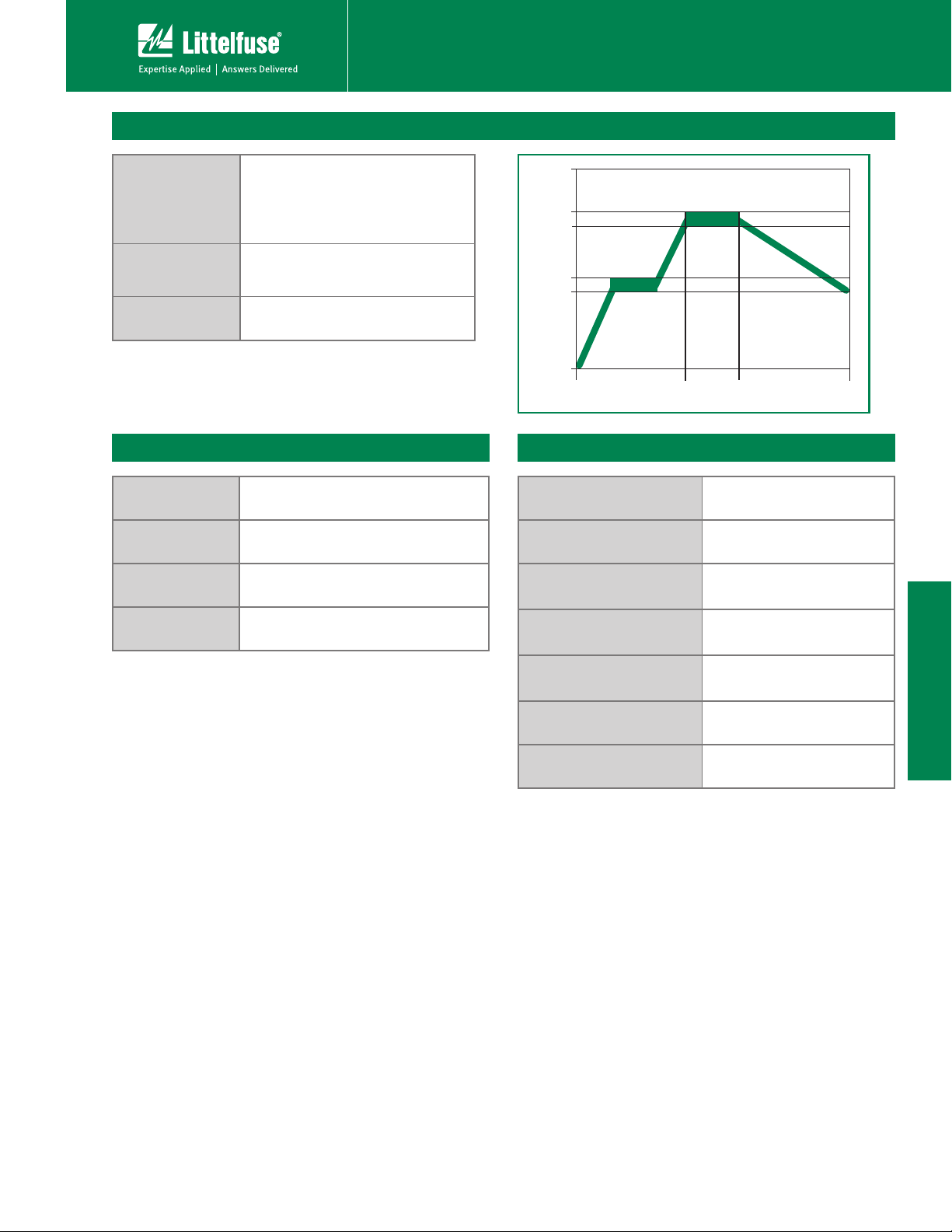
Soldering Parameters - Wave Soldering
Refer to the condition recommended by
Pre-Heating Zone
the flux manufacturer.
Max. ramping rate should not exceed
4°C/Sec.
POLYFUSE® Resettable PTCs
Radial Leaded > 72R Series
260
220
Soldering Cooling
Soldering Zone
Max. solder temperature should not
exceed 260°C
Cooling Zone Cooling by natural convection in air.
Physical Specifications
Lead Material
Soldering
Characteristics
Insulating Material
Lead Solderability
0.20-0.40A: Tin-plated Copper clad steel
0.50-3.75A: Tin-plated Copper
Solderability per MIL–STD–202, Method
208E
Cured, flame retardant epoxy polymer
meets UL 94V-0 requirements.
Marked with ‘LF’, voltage, current rating,
and date code.
190
160
Temperature (°C)
0
Preheating
60 min.
5 max.
Time(s)
Environmental Specifications
Operating/Storage
Temperature
Maximum Device Surface
Temperature in Tripped State
Passive Aging
Humidity Aging
Thermal Shock
-40°C to +85°C
125°C
+85°C, 1000 hours
-/+5% typical resistance change
+85°C, 85% R.H. 1000 hours
-/+5% typical resistance change
+85°C to -40°C 10 times
-/+5% typical resistance change
72R Series
© 2010 Littelfuse, Inc
Specifications are subject to change without notice.
Please refer to www.littelfuse.com/series/72R.html for current information.
Solvent Resistance MIL–STD–202, Method 215F
Moistrue Sesitivity Level Level 1, J–STD–020C
93
Revised: July 12, 2010
72R Series
Page 4

POLYFUSE® Resettable PTCs
Radial Leaded > 72R Series
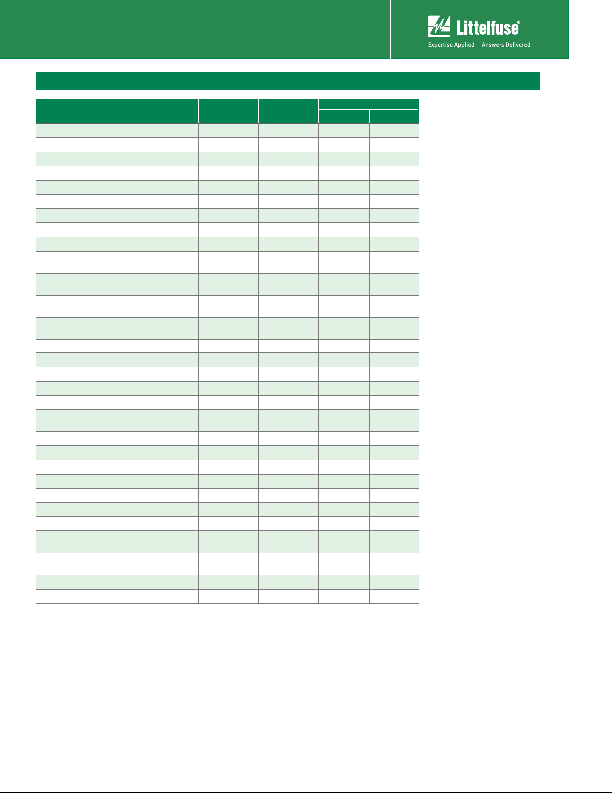
Dimensions
A
E
B
Part Marking System
Littelfuse
Trademark
Single Sided Marking
72
020X
XXXX
Voltage Rating
Current Rating
Date Code
(Contact Littelfuse
for additional
information)
D
C
A B C D E Physical Characteristics
Part Number
72R020X 0.29 7.4 0.46 11.7 0.20 5.1 0.30 7.6 0.12 3.1 0.02 0.51 Sn/CuFe
72R025X 0.29 7.4 0.50 12.7 0.20 5.1 0.30 7.6 0.12 3.1 0.02 0.51 Sn/CuFe
72R030X 0.29 7.4 0.50 12.7 0.20 5.1 0.30 7.6 0.12 3.1 0.02 0.51 Sn/CuFe
72R040X 0.30 7.6 0.53 13.5 0.20 5.1 0.30 7.6 0.12 3.1 0.02 0.51 Sn/CuFe
72R050X 0.31 7.9 0.54 13.7 0.20 5.1 0.30 7.6 0.12 3.1 0.02 0.51 Sn/Cu
72R065X 0.37 9.4 0.57 14.5 0.20 5.1 0.30 7.6 0.12 3.1 0.02 0.51 Sn/Cu
72R075X 0.40 10.2 0.60 15.2 0.20 5.1 0.30 7.6 0.12 3.1 0.02 0.51 Sn/Cu
72R090X 0.44 11.2 0.62 15.8 0.20 5.1 0.30 7.6 0.12 3.1 0.02 0.51 Sn/Cu
72R110X 0.51 13.0 0.72 18.2 0.20 5.1 0.30 7.6 0.12 3.1 0.03 0.81 Sn/Cu
72R135X 0.53 13.58 0.78 19.8 0.20 5.1 0.30 7.6 0.12 3.1 0.03 0.81 Sn/Cu
72R160X 0.60 15.36 0.85 21.6 0.20 5.1 0.30 7.6 0.12 3.1 0.03 0.81 Sn/Cu
72R185X 0.66 16.76 0.91 23.0 0.20 5.1 0.30 7.6 0.12 3.1 0.03 0.81 Sn/Cu
72R250X 0.78 19.93 1.03 26.2 0.40 10.2 0.30 7.6 0.12 3.1 0.03 0.81 Sn/Cu
72R300X 0.91 23.11 1.15 29.3 0.40 10.2 0.30 7.6 0.12 3.1 0.03 0.81 Sn/Cu
72R375X 1.04 26.3 1.22 31.1 0.40 10.2 0.30 7.6 0.12 3.1 0.03 0.81 Sn/Cu
Inches mm Inches mm Inches mm Inches mm Inches mm Lead (dia)
Max. Max. Max. Max. Typ. Typ. Min. Min. Max. Max. Inches mm
Material
72R Series
94
Revised: July 12, 2010
© 2010 Littelfuse, Inc.
Please refer to www.littelfuse.com/series/72R.html for current information.
Specifications are subject to change without notice.
Page 5

Part Ordering Number System
72 R 090 X P R
PACKAGING STYLE
SERIES
R: RADIAL
VOLTAGE RATING (VDC)
Packaging
I
HOLD
QUANTITY CODE: F=200 H=100 M=1000 P=2000 U=500
TYPE: X (72VDC)
CURRENT CODE (See to Electrical Characteristics table)
POLYFUSE® Resettable PTCs
Radial Leaded > 72R Series
BLANK: Bulk
R: Tape & Ammo
Part Number
72R020X
72R025X
72R030X
72R040X
72R050X
72R065X
72R075X
72R090X
72R110X
72R135X
72R160X
72R185X
72R250X
72R300X
Ordering Part
Number
72R020XU
72R020XPR Tape and Ammo 2000 PR
72R025XU
72R025XPR Tape and Ammo 2000 PR
72R030XU
72R030XPR Tape and Ammo 2000 PR
72R040XU
72R040XPR Tape and Ammo 2000 PR
72R050XU
72R050XPR Tape and Ammo 2000 PR
72R065XU
72R065XPR Tape and Ammo 2000 PR
72R075XU
72R075XPR Tape and Ammo 2000 PR
72R090XU
72R090XPR Tape and Ammo 2000 PR
72R110XU
72R110XMR Tape and Ammo 1000 MR
72R135XF
72R135XMR Tape and Ammo 1000 MR
72R160XF
72R160XMR Tape and Ammo 1000 MR
72R185XF
72R185XMR Tape and Ammo 1000 MR
72R250XF
72R250XMR Tape and Ammo 1000 MR
72R300XF
72R300XMR Tape and Ammo 1000 MR
I
(A)
hold
I
hold
Code
0.20 020
0.25 025
0.30 030
0.40 040
0.50 050
0.65 065
0.75 075
0.90 090
1. 10 11 0
1.35 135
1.60 160
1.85 185
2.50 250
3.00 300
Packaging
Option
Quantity
Packaging Codes
Bulk 500 U
Bulk 500 U
Bulk 500 U
Bulk 500 U
Bulk 500 U
Bulk 500 U
Bulk 500 U
Bulk 500 U
Bulk 500 U
Bulk 200 F
Bulk 200 F
Bulk 200 F
Bulk 200 F
Bulk 200 F
Quantity &
72R375X 72R375XH 3.75 375 Bulk 100 H
72R Series
© 2010 Littelfuse, Inc
Specifications are subject to change without notice.
Please refer to www.littelfuse.com/series/72R.html for current information.
95
Revised: July 12, 2010
72R Series
Page 6
POLYFUSE® Resettable PTCs
Radial Leaded > 72R Series
Tape and Ammo Specifications
Devices taped using EIA468-B/IE286-2 standards. See table below and Figure 1 for details.
Dimension EIA Mark
Carrier tape width WW18 –0.5 / +1.0
Hold down tape width W
Top distance between tape edges W
Sprocket hole position W
Sprocket hole diameter* D
4
6
5
0
Abscissa to plane (straight lead) HH18.5 –/+ 3.0
Abscissa to plane (kinked lead) H
Abscissa to top 72R020X–72R090X H
Abscissa to top 72R110X–72R300X H
Overall width without lead protrusion:
72R020X–72R090X
0
1
1
C
1
Overall width without lead protrusion:
72R110X–72R300X
Overall width with lead protrusion:
72R020X–72R090X
C
2
Overall width with lead protrusion:
72R110X–72R300X
Lead protrusion L
1
Protrusion of cut out LL11 max.
Protrusion beyond hold–down tape l
Sprocket hole pitch: 72R020X–72R090X P
Sprocket hole pitch: 72R110X–72R300X P
2
0
0
Pitch tolerance
Device pitch: 72R020X–72R090X 12.7
Device pitch: 72R110X–72R300X 25.4
Tape thickness tt0.9 max.
Tape thickness with splice t
Splice sprocket hole alignment
1
Body lateral deviation Δh Δh 0 –/+ 1.0
Body tape plane deviation Δp Δp 0 –/+ 1.3
Ordinate to adjacent component lead*:
72R020X–72R090X
P
1
Ordinate to adjacent component lead*:
72R110X–72R300X
Lead spacing: 72R020X–72R185X FF5.08 –/+ 0.8
Lead spacing: 72R250X–72R300X FF10.18 –/+ 0.8
IEC Mark
W
0
W
2
W
1
D
0
H
0
H
1
Dim. (mm) Tol. (mm)
11 min.
3 max.
9 –0.5 / +0.75
4 –0.32 / +0.2
16 –/+ 0.5
32.2 max.
47.5 max.
42.5 max.
57
43.2 max.
58
l
1
l
2
P
0
P
0
1.0 max.
Not specified
12.7 –/+ 0.3
25.4 –/+ 0.5
20
consecutive.
2.0 max.
0 –/+ 0.3
P
1
3.81 –/+ 0.7
7.62 –/+ 0.7
Dimensions
–/+ 1
*Differs from EIA Specification
72R Series
96
Revised: July 12, 2010
© 2010 Littelfuse, Inc.
Please refer to www.littelfuse.com/series/72R.html for current information.
Specifications are subject to change without notice.
Page 7
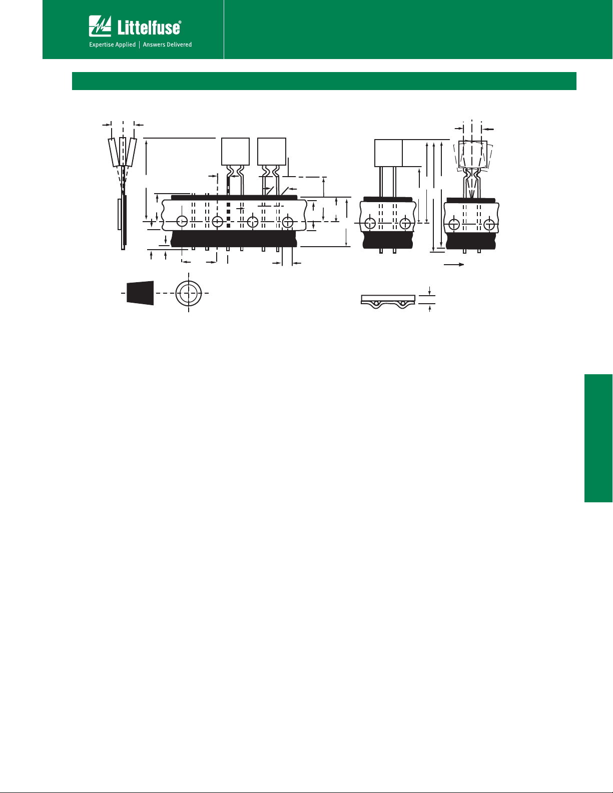
Tape and Ammo Diagram
POLYFUSE® Resettable PTCs
Radial Leaded > 72R Series
Figure 1
Δh
H
Δh
1
Δh
Δp
Reference plane
A
1
F
H
L
I
2
P
L
1
0
A
B
0
W
W
D
0
5
4
W
Direction of unreeling
C
H
1
1
C
H
2
Cross section A - B
t
72R Series
© 2010 Littelfuse, Inc
Specifications are subject to change without notice.
Please refer to www.littelfuse.com/series/72R.html for current information.
97
Revised: July 12, 2010
72R Series
 Loading...