

Page 1
468 Series Fuse
Surface Mount Fuses
Thin Film > 1206 Size > Slo-Blo® > 468 Series
Description
The 468 Series Time-Lag (Slo-Blo®) SMF is a small (1206
size) thin-film device designed for secondary protection
of circuits used in space constrained applications such as
hand-held portable electronic devices.
This series is 100% lead-free and meets the requirements
of the RoHS directive. New Halogen-Free 468 Series
fuses are available–to order use the “HF” suffix. See Part
Numbering section for additional information.
Agency Approvals
AGENCY AGENCY FILE NUMBER AMPERE RANGE
E10480 500MA - 3A
LR29862 500MA - 3A
Electrical Characteristics for Series
% of Ampere
Rating
100% 4 hours, Minimum
200% 1 sec., Min.; 120 sec., Max.
300% 0.05 sec., Min.; 1.5 sec., Max
800% 0.0015 sec., Min.; .05 sec., Max.
Opening Time at 25
O
C
Additional Information
Datasheet
Resources
Samples
Features
• Complieswith
electronic industry
environmental standards
for lead reduction.
• Productiscompatible
with lead-free solders
and higher temperature
• Packageisvisually
distinct from fastacting version for easy
identification.
• Topsidemarkingallows
visual verification of
amperage rating.
profiles.
• Timedelayfeature
withstands high inrush
currents and prevents
nuisance openings.
Applications
Secondary protection for space constrained applications:
• Cellphones
• Batterypacks
• DVDplayers
• Harddiskdrives.
• Digitalcameras
Electrical Specifications by Item
Ampere
Rating
(A)
0.50 .500 63
1. 0 0 00 1. 63 0.08250 0.1270 94.70 0.0947 x x
1.50 01. 5 63 0.04750 0.2880 82.32 0.1235 x x
2.00 002. 63 35 amperes @63 VAC
2.50 02.5 63 0.02240 1.0110 73.92 0.1848 x x
3.00 003. 32 50 amperes @32
1. Measured at 10% of rated current, 25˚C.
2. Measured at rated voltage.
Amp
Code
Max
Voltage
Rating
(V)
Interrupting
Rating
50 amperes @63
VAC/VDC
50 amperes @63
VDC
VAC/VDC
Nominal Cold
Resistance
(Ohms)
0.27000 0.0310 156.77 0.0784 x x
0.03240 0.5060 77.27 0.1545 x x
0.01950 1.2700 72.95 0.2189 x x
Nominal
Melting
2
t (A2sec)
I
Nom
Voltage
Drop
(mV)
Nom
Power
Dissipation
(W)
Specifications are subject to change without notice.
Approvals
© 2013 Littelfuse, Inc.
Agency
Revised: 12/19/13
Page 2
Surface Mount Fuses
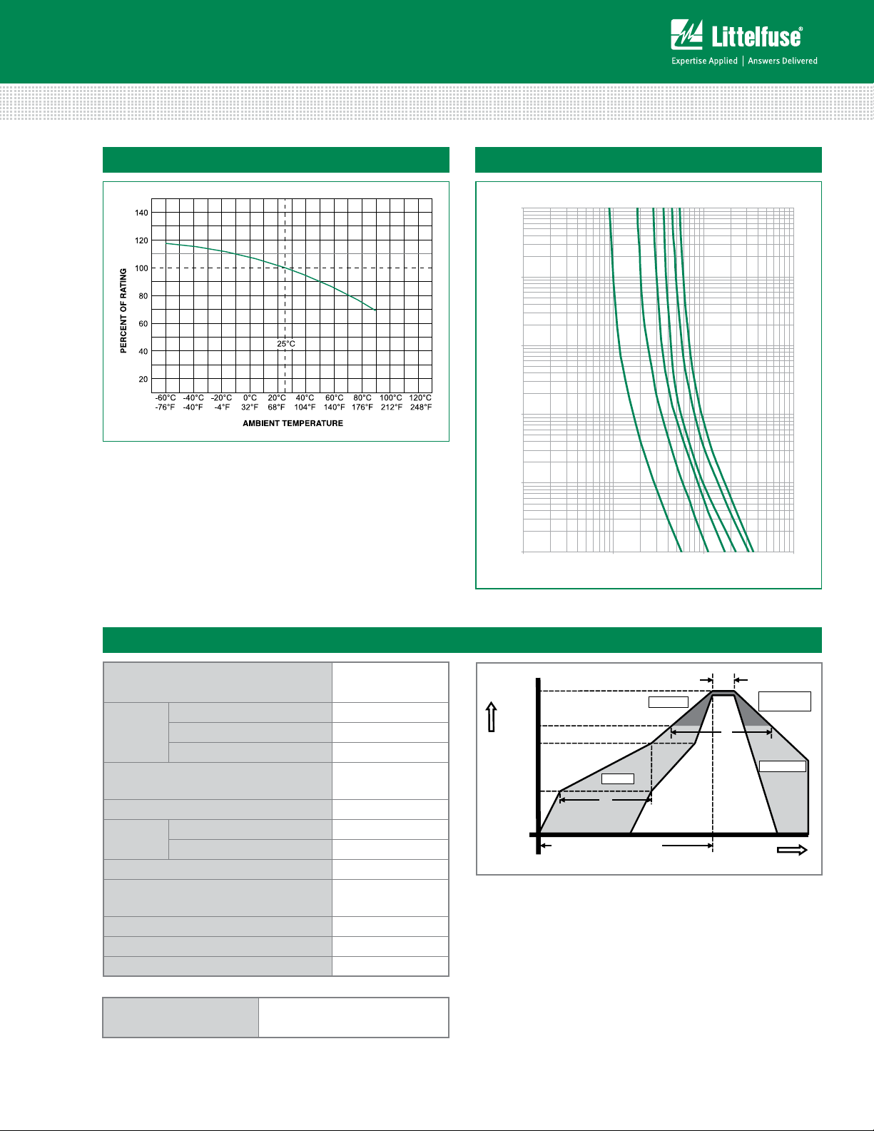
0
Current in Amperes
Time in Seconds
5A
Thin Film > 1206 Size > Slo-Blo® > 468 Series
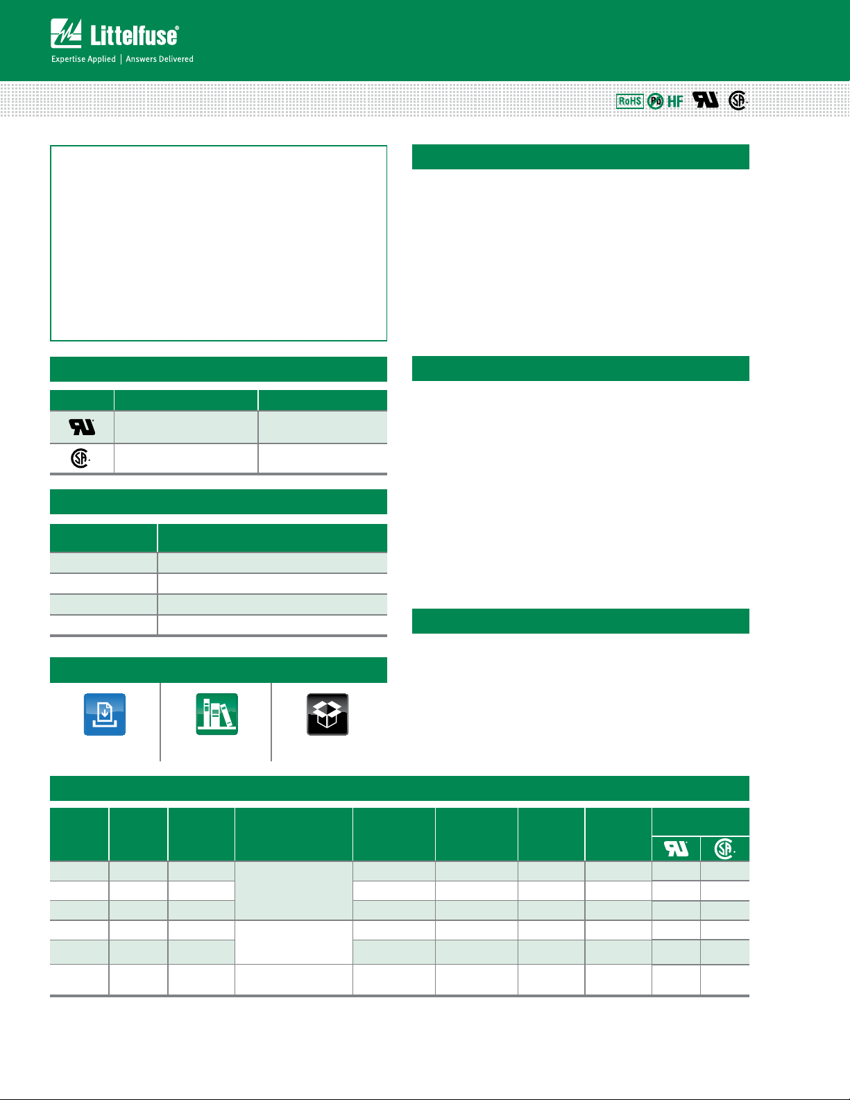
Average Time Current CurvesTemperature Rerating Curve
Note:
1. Derating depicted in this curve is in addition to the standard derating of 25% for
continuous operation.
Example:
For continuous operation at 70 degrees celsius, the fuse should be deratedas follows:
I = (0.75)(0.80)I
2. The temperature derating curve represents the nominal conditions. For questions
about temperature derating curve, please consult Littelfuse technical support
for assistance.
= (0.60)I
RAT
RAT
0.01
0.001
1A
100
10
1
0.1
.5A
3A
2.
2A
1.5A
010110
Soldering Parameters
Reflow Condition Pb – Free assembly
- Temperature Min (T
Pre Heat
- Temperature Max (T
- Time (Min to Max) (ts) 60 – 180 secs
Average ramp up rate (Liquidus Temp
(T
) to peak
L
to TL - Ramp-up Rate 5°C/second max
T
S(max)
Reflow
- Temperature (TL) (Liquidus) 217°C
- Temperature (tL) 60 – 150 seconds
Peak Temperature (TP) 260
Time within 5°C of actual peak
Temperature (t
)
p
Ramp-down Rate 5°C/second max
Time 25°C to peak Temperature (T
Do not exceed 260°C
Wave Soldering 260°C, 10 seconds max.
) 150°C
s(min)
) 200°C
s(max)
5°C/second max
+0/- 5
20 – 40 seconds
) 8 minutes Max.
P
°C
T
Temperature
S(max)
T
S(min)
T
P
T
L
25
time to peak temperature
Preheat
t
S
(t 25ºC to peak)
Ramp-up
t
P
Critical Zone
T
to T
L
P
t
L
Ramp-down
Time
© 2013 Littelfuse, Inc.
Specifications are subject to change without notice.
Revised: 12/19/13
Page 3

Product Characteristics
Surface Mount Fuses
Thin Film > 1206 Size > Slo-Blo® > 468 Series
Body: Epoxy Substrate
Materials
Terminations: 100% Tin over Nickel over
Copper
Element Cover Coat: Conformal Coating
O
–55
Operating
Temperature
C to 90OC. Consult temperature
rerating curve chart. For operation above
90°C please contact Littelfuse
Thermal Shock Withstands 5 cycles of – 50
O
C to 125OC
Vibration
Insulation Resistance
(After Opening)
Resistance to
Soldering Heat
Humidity MIL-STD-202F, Method 103B, Condition D
Dimensions Part Marking System
MARKING CODE VARIES
WITH AMPERAGE RATING
(SEE CHART)
3.18
(.125")
1.65
(.065")
1.52
(.060")
WAVE SOLDER
2.03
(.080")
(.190")
4.83
1.27
(.050")
1.52
(.060")
.66
(.026")
Coating
2.03
(.080")
1.52
(.060")
1.14
(.045")
3.81
(.150")
INFARED SOLDER
.58
(.023")
Amp
Code
Marking
Code
.500 TF
0 01. TH
01.5 TK
002. TN
02.5 TO
003. TP
Part Numbering System
SERIES
AMP Code
The dot is poisitioned before the Packaging Suffix with whole ratings and
within the numbering sequence for
fractional ratings. Refer to Amp Code
column in the Electrical Specifications
table.
PACKAGING Code
NR = Tape and Reel, 5000 pcs
‘HF’ SUFFIX
HALOGEN FREE ITEM
Withstands 10-55 Hz per MIL-STD-202F,
Method 201A and
10-2000 Hz at 20 G’s per MIL-STD-202F,
Method 204D, Condition D
Greater than 10,000 ohms.
MIL-STD-202G, Method 210F,
Condition D
0468002.NRHF
Example:
1.5 amp product is
046801.5NRHF (2 amp
product shown above).
Packaging
Packaging Option Packaging Specification Quantity
Tape & Reel – 8mm tape EIA-481 Rev. D (IEC 60286, part 3) 5000 NR
Quantity &
Packaging Code
Specifications are subject to change without notice.
© 2013 Littelfuse, Inc.
Revised: 12/19/13
 Loading...