

Page 1
443 Series Fuse
Surface Mount Fuses
NANO
2®
> 250V > Time Lag > 443 Series
Description
The 250V Nano2 Fuse is a small square surface mount
fuse that is designed to enable compliance with the RoHS
directive. This product is fully compatible with lead-free
solder alloy and higher temperature profiles associated
with lead-free assembly.
Features
• 250VACvoltagerating
• Time-Lag
• Available0.50A–5.00A
• RoHSCompliant
• Fullycompatiblewith
lead-free solder alloys
and higher temperature
profiles associated with
lead-free assembly
Agency Approvals
Applications
AGENCY AGENCY FILE NUMBER AMPERE RANGE
E10480 0.500A - 5.00A
Electrical Characteristics for Series
% of Ampere
Rating
100% 4 hours, Minimum
250% 120 seconds, Maximum
Opening Time
• AC/DCpoweradaptor
• Telecomequipment
system power
• Portablesystembuilt-in
AC/DC converter
Additional Information
Datasheet
Resources
• HighvoltageDC/DC
converter
• LightingSystem
• LEDLighting
Electrical Specifications by Item
Ampere
Rating
(A)
0.50 .500 250
0.75 .750 250 0.275 1.0 0 285 x
1 0 01. 250 0.180 10.17 234 x
1.50 01. 5 250 0.100 14.72 196 x
2 002. 250 0.052 18.06 154 x
2.50 02.5 250 0.035 18.13 139 x
3 003. 250 0.028 51.44 113 x
3.50 03.5 250 0.019 53.14 98 x
4 004. 250 0.016 70.56 81 x
5 005. 250 0.0115 127.79 80
Notes:
1. Cold resistance measured at less than 10% of rated current at 23°C.
2. Agency Approval Table Key: X=Approved or Certified, P=Pending and Blank=Not Approved
3. Have special electrical characteristic needs? Contact Littelfuse to learn more about application specific options.
Amp Code
Max
Voltage
Rating
(V)
Interrupting
Rating
50A @250VAC
Nominal Cold
Resistance
(Ohms)
0.600 1.61 448
Nominal
Melting
2
t (A2sec)
I
Nominal
Voltage Drop
(mV)
Samples
Agency
Approvals
x
x
Specifications are subject to change without notice.
© 2013 Littelfuse, Inc.
Revised: 12/19/13
Page 2
Surface Mount Fuses
CURRENT IN AMPS
NANO2® > 250V > Time Lag > 443 Series
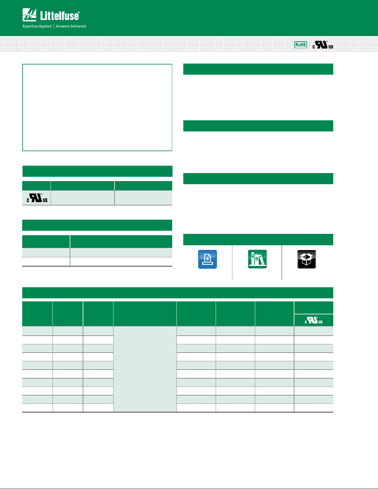
Temperature Rerating Curve
Note:
1. Derating depicted in this curve is in addition to the standard derating of 25% for
continuous operation.
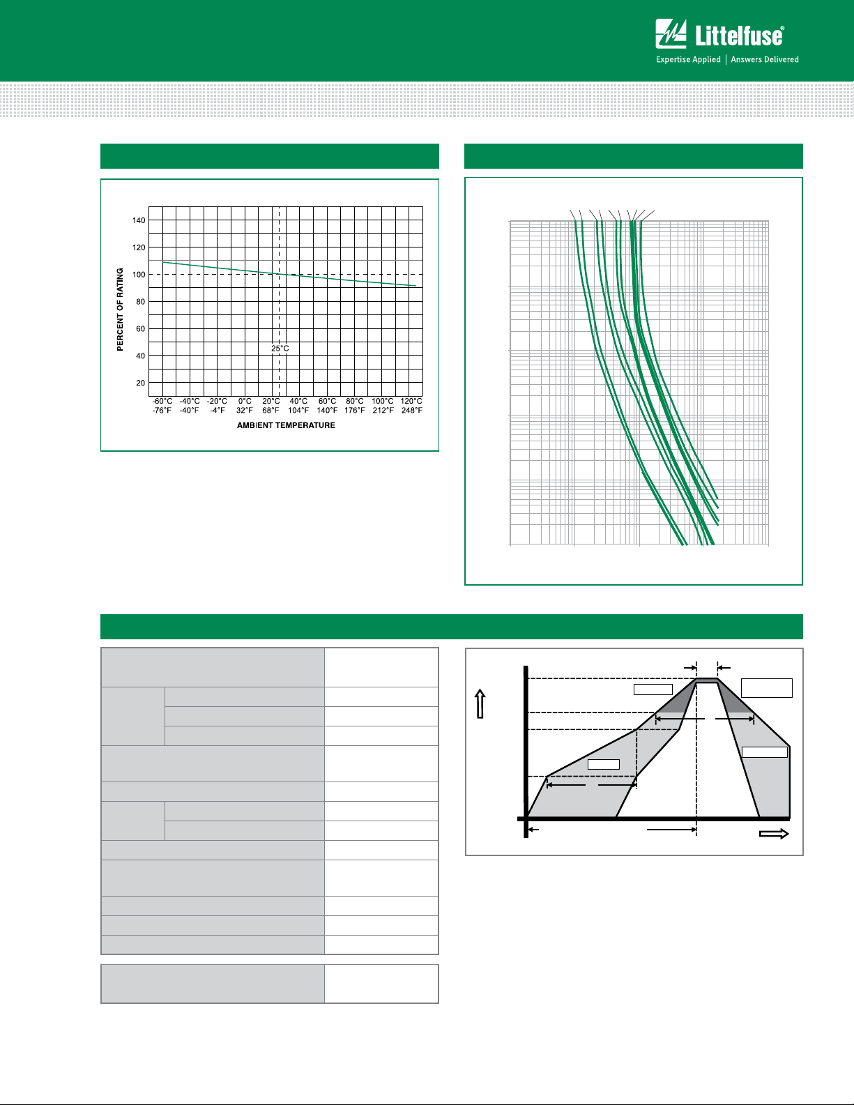
Average Time Current Curves
0.50 A
0.75 A
1.00 A
1.50 A
2.00 A
2.50 A
3.00 A
3.50 A
4.00 A
5.00 A
100
10
1
TIME IN SECONDS
0.1
0.01
0.001
0.1 110100 1000
Soldering Parameters
Reflow Condition Pb – Free assembly
- Temperature Min (T
Pre Heat
- Temperature Max (T
- Time (Min to Max) (ts) 60 – 120 secs
Average ramp up rate (Liquidus Temp
(T
) to peak
L
to TL - Ramp-up Rate 5°C/second max.
T
S(max)
Reflow
- Temperature (TL) (Liquidus) 217°C
- Temperature (tL) 60 – 90 seconds
Peak Temperature (TP) 260
Time within 5°C of actual peak
Temperature (t
)
p
Ramp-down Rate 5°C/second max.
Time 25°C to peak Temperature (T
Do not exceed 260°C
Wave Soldering Parameters
) 150°C
s(min)
) 200°C
s(max)
5°C/second max.
+0/–5
°C
20 – 40 seconds
) 8 minutes max.
P
260°C Peak
Temperature,
3 seconds max.
Temperature
T
T
T
T
S(max)
S(min)
25
P
L
time to peak temperature
(t 25ºC to peak)
Preheat
t
S
Ramp-up
t
P
Critical Zone
T
to T
L
P
t
L
Ramp-down
Time
© 2013 Littelfuse, Inc.
Specifications are subject to change without notice.
Revised: 12/19/13
Page 3

Product Characteristics
Surface Mount Fuses
NANO
2®
> 250V > Time Lag > 443 Series
Materials
Body: Ceramic
Cap: Silver Plated Brass
Body: Brand Logo, Current Rating
Product Marking
Rated Voltage, T - C
Characteristic “T”
Insulation Resistance
(after Opening)
MIL-STD-202, Method 302,
Test Condition A (10,000 ohms,
Minimum)
Solderability MIL-STD-202, Method 208
Resistance to
Soldering Heat
Moisture Sensitivity
Level
MIL-STD-202, Method 210,
Test Condition B (10 sec at 260
Level 1 J-STD-020C
Min. copper layer thickness = 100um
Min. copper trace width = 10mm
PCB
Recommendation
for Thermal
Management
Alternate methods of thermal management may be used. In such cases,
under normal operations, the maximum
temperature of the fuse body should
not exceed 80
O
C in a 25OC ambient
environment.
Dimensions
Operating Temperature –55OC to 125OC with proper derating
Thermal Shock
MIL-STD-202F, Method 107G,
Test Condition B (5 cycles -65
o
C
to +125oC)
Vibration
MIL-STD-202F, Method 201A
(10-55 Hz)
MIL-STD-202, Method 106,
Moisture Resistance
Salt Spray
o
C)
Mechanical Shock
High Humidity (90-98%RH), Heat
o
C)
(65
MIL-STD-202F, Method 101,
Test Condition B
MIL-STD-202, Method 213,
Test Condition I (100 G’s peak for
6 milliseconds)
Part Numbering System
3.25
(.128")
6.10
3.43
(.135")
12.6
3.12
(.123")
10.10
(.397")
5A
AC250V
T
1.70 typ
(.067")
3.12
(.123")
Recommended Pad Layout
(.240")
(.496")
Packaging
Packaging Option Packaging Specification Quantity
24mm Tape and Reel
EIA-RS 481-2 (IEC 286, part 3)
0443 .500 D R
SERIES
AMP Code
Refer to Electrical
characteristics table
qUANTITY Code
D = 1500 pcs
PACKAGING Code
R = Tape and Reel
Example:
1.5 amp product is
0443 01.5 D R (0.5 amp
product shown above).
Quantity &
Packaging Code
1500 DR
Specifications are subject to change without notice.
© 2013 Littelfuse, Inc.
Revised: 12/19/13
 Loading...