

Page 1
Surface Mount Fuses
Thin Film > 0402 Size > Very Fast-Acting > 435 Series
435 Series Fuse
Agency Approvals
AGENCY AGENCY FILE NUMBER AMPERE RANGE
E10480 0.250 - 5.0A
LR 29862 0.250 - 5.0A
Description
The 435 Series are fast-acting surface mount thin-film
fuses. Their ultra-small size (0402 size) makes them ideal for
secondary protection of circuits used in space constrained
applications such as hand-held portable electronic devices.
This series is 100% lead-free and meet the requirements of
the RoHS directive. New Halogen-Free 435 Series fuses are
available–to order use the “HF” suffix. See Part Numbering
section for additional information.
Features
• 35Ainterruptratingat
32VDC
• Smallsizewithcurrent
ratings of 0.25 to 5.0
amperes
• RoHScompliant,lead-free
and halogen-free
• Maximumprotectionof
sensitive circuits as fuses
are designed to open
consistently in <5sec at
200% overload.
• EnhancedBreaking
Capacity, High l
2
t
Applications
Electrical Characteristics for Series
Secondary protection for space constrained applications
such as:
% of Ampere
Rating
100% 0.250A - 5A 4 hours, Minimum
200% 0.375A - 5A 5 secs., Maximum
300% 0.250A 5 secs., Maximum
300% 0.375A - 5A 0.2 sec., Maximum
Ampere
Rating
Opening Time at 25
O
C
• Cellphones
• Batterypacks
• DVDplayers
• Harddiskdrives.
• Digitalcameras
Additional Information
Datasheet
Resources
Samples
Electrical Specifications by Item
Ampere
Rating
(A)
0.250 .250 32
0.375 .375 32 0.1930 0.0035 84.64 0.03174 x x
0.500 .500 32 0.1600 0.0053 93.35 0.04668 x x
0.750 .750 32 0.1050 0.0120 101.84 0.07638 x x
1. 0 0 0 01. 32 0.0730 0.0200 87.45 0.08745 x x
1.25 1.25 32 0.0600 0.0350 96.37 0.12046 x x
1.50 01.5 32 0.0470 0.0560 86.70 0.13005 x x
1.75 1.75 32 0.0390 0.0750 81.13 0.14198 x x
2.00 002. 32 0.0300 0.1000
2.50 02.5 32 0.0185 0.1560
3.00 003. 32 0.0165 0.2032
3.50 03.5 32 0.0135 0.3017
4.00 004. 32 0.0115 0.3084
5.00 005. 32 0.0085 0.5310
1. Measured at 10% of rated current, 25ºC.
2. Measured at rated voltage.
© 2013 Littelfuse, Inc.
Specifications are subject to change without notice.
Revised: 12/19/13
Amp
Code
Max Voltage
Rating
(V)
Interrupting
Rating
35A @32V
DC
Nominal Cold
Resistance
(Ohms)
0.2265 0.0025 60.67 0.01517 x x
Nominal
Melting
2
t (A2sec)
I
Nom
Voltage Drop
(mV)
Nom Power
Dissipation
(W)
70.62 0.14120 x x
55.25 0.13813 x x
60.58 0.18740 x x
57.84 0.20244 x x
57.00 0.22800 x x
52.44 0.26220 x x
Agency Approvals
Page 2
Surface Mount Fuses
Thin Film > 0402 Size > Very Fast-Acting > 435 Series
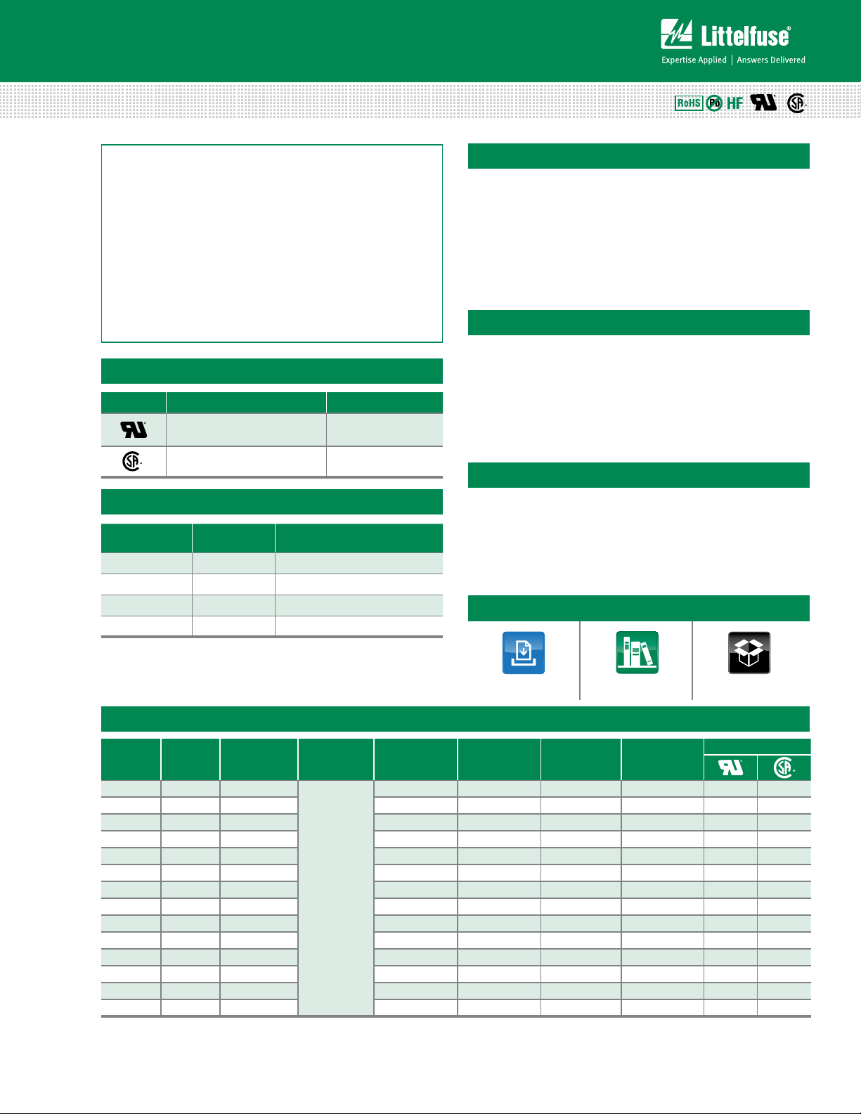
Temperature Rerating Curve
Note:
1. Derating depicted in this curve is in addition to the standard derating of 25% for
continuous operation.
Example:
For continuous operation at 70 degrees celsius, the fuse should be deratedas follows:
I = (0.75)(0.80)I
2. The temperature derating curve represents the nominal conditions. For questions
about temperature derating curve, please consult Littelfuse technical support
for assistance.
= (0.60)I
RAT
RAT
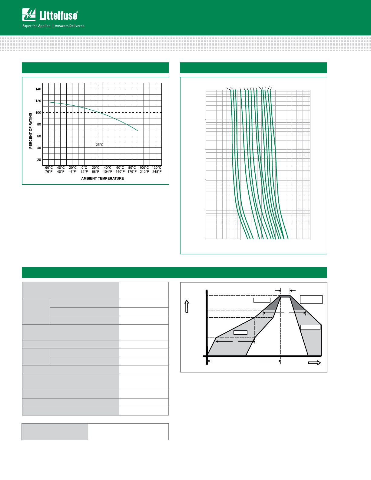
Average Time Current Curves
1.5A
1A
.25A
.5A
.375A
1.25A
100
10
1
TIME IN SECONDS
0.1
0.01
0.001
0.1 1.0 10.0 100.0
.75A
CURRENT IN AMPERES
2A
2.5A
3A
4A
3.5A
1.75A
5A
Soldering Parameters
Reflow Condition Pb – Free assembly
- Temperature Min (T
Pre Heat
- Temperature Max (T
- Time (Min to Max) (ts) 60 – 120 secs
Average ramp up rate (Liquidus Temp
(T
) to peak
L
to TL - Ramp-up Rate 5°C/second max
T
S(max)
Reflow
- Temperature (TL) (Liquidus) 217°C
- Temperature (tL) 60 – 150 seconds
Peak Temperature (TP) 250
Time within 5°C of actual peak
Temperature (t
)
p
Ramp-down Rate 5°C/second max
Time 25°C to peak Temperature (T
Do not exceed 260°C
Wave Soldering 260°C, 10 seconds max.
) 150°C
s(min)
) 200°C
s(max)
5°C/second max
+0/-5
°C
20 – 40 seconds
) 8 minutes Max.
P
T
Temperature
S(max)
T
S(min)
T
P
T
L
25
time to peak temperature
Preheat
t
S
(t 25ºC to peak)
Ramp-up
t
P
Critical Zone
T
to T
L
P
t
L
Ramp-down
Time
Specifications are subject to change without notice.
© 2013 Littelfuse, Inc.
Revised: 12/19/13
Page 3

Surface Mount Fuses
.558
(.022")
Reow solder
recommended
mounting pad
dimensions
.991 +/- .051
(.039" +/- .002")
Marking code varies
with amperage.
Refer to Part Marking
System chart.
Cu
.508 +/- .051
(.020" +/- .002")
.229 +/- .102
(.009" +/- .004")
0.330 +/- .102
(.013" +/- .004")
.381
(.015")
1.55
(.061")
.584
(.023")
0.292 +/- .102
(.012" +/- .004")
.2159 +/- .0889
(.0085" +/- .0035")
Sn
A
B
C
D
Thin Film > 0402 Size > Very Fast-Acting > 435 Series
Product Characteristics
Materials
Terminal
Strength
Insulation
Resistance
Dimensions
Body: Epoxy / Glass Substrate;
Parts with ‘HF’ suffix: Halogen Free Epoxy / Glass
Terminations: 100% Tin over Nickel over Copper
Device Weight: 0.316mg
MIL-STD-202F, Method 211A, Test Condition A
After Opening: Greater than 10,000Ohms
Operating
Temperature
Consult temperature rerating curve chart.
For operation above 90°C please contact
Littelfuse.
Thermal Shock Withstands 5 cycles of –55°C to 125°C
Vibration MIL-STD-202F
Part Marking System
–55°C to 90°C.
Amp
Code
.375
.500
.750
001.
1.25
01.5
1.75
002.
02.5
003.
03.5
004.
005.
.250
Marking
Code
X
Part Numbering System
0435 002. K R HF S
A B C D
inch min 0.037 0.018 0.008 0.005
inch max 0.041 0.022 0.016 0.012
mm min 0.94 0.457 0.190 0.127
mm max 1.04 0.559 0.394 0.305
Packaging
Packaging Option Packaging Specification Quantity Quantity & Packaging Code
8mm Tape and Reel EIA-481 Rev. D (IEC 60286, part 3) 10000 KR
© 2013 Littelfuse, Inc.
Specifications are subject to change without notice.
Revised: 12/19/13
SERIES
Refer to Amp Code column in the
Electrical Specifications table.
The dot is positioned at the end of the
number sequence with whole ratings
and within for fractional ratings.
Example: 1.5 amp product is
043501.5KRHF (2 amp product shown)
qUANTITY Code
K = 10,000 Pieces
PACKAGING Code
R = Tape and Reel
HALOGEN FREE ITEM
“S” - for .250A only
 Loading...