

Page 1
Axial Lead & Cartridge Fuses
3AB > Time Lag > 325/326 Series
325/326 Series Lead-Free 3AB, Slo-Blo® Fuse
PS
E
Description
The 3AB Slo-Blo® Fuse with ceramic body construction
permits higher interrupting ratings and voltage ratings.
Ideal for applications where high current loads are
expected.
Features
Agency Approvals
Agency Agency File Number Ampere Range
E10480 250mA - 10A
E10480 12A - 30A
LR 29862 250mA - 30A
NBK 030805-
PS
E
E10480A-F/
NBK 260106JP1021A/B
SU05001-5010
SU05001-5011
SU05001-5012
SU05001-7005
1A - 30A
2.5A - 3.2A/
7A - 20A
10mA - 30A
• InaccordancewithUL
Standard 248-14
• RoHScompliantand
Lead-free
• Availableincartridge
and axial lead format
and with various forming
dimensions
Applications
Used as supplementary protection in appliance or
utilization equipment to provide individual protection for
components or internal circuits.
Electrical Characteristics for Series
% of Ampere
Rating
100% 100mA – 30A 4 hours, Minimum
135% 100mA – 30A 1 hour, Maximum
200%
Ampere Rating Opening Time
100mA – 3.2A 5 sec., Min., 30 sec., Max.
4A – 30A 5 sec., Min., 60 sec., Max.
Additional Information
© 2013 Littelfuse, Inc.
Specifications are subject to change without notice.
Revised: 12/19/13
Datasheet
325 Series
Datasheet
326 Series
Resources
325 Series
Resources
326 Series
Samples
325 Series
Samples
326 Series
Page 2
Axial Lead & Cartridge Fuses
3AB > Time Lag > 325/326 Series
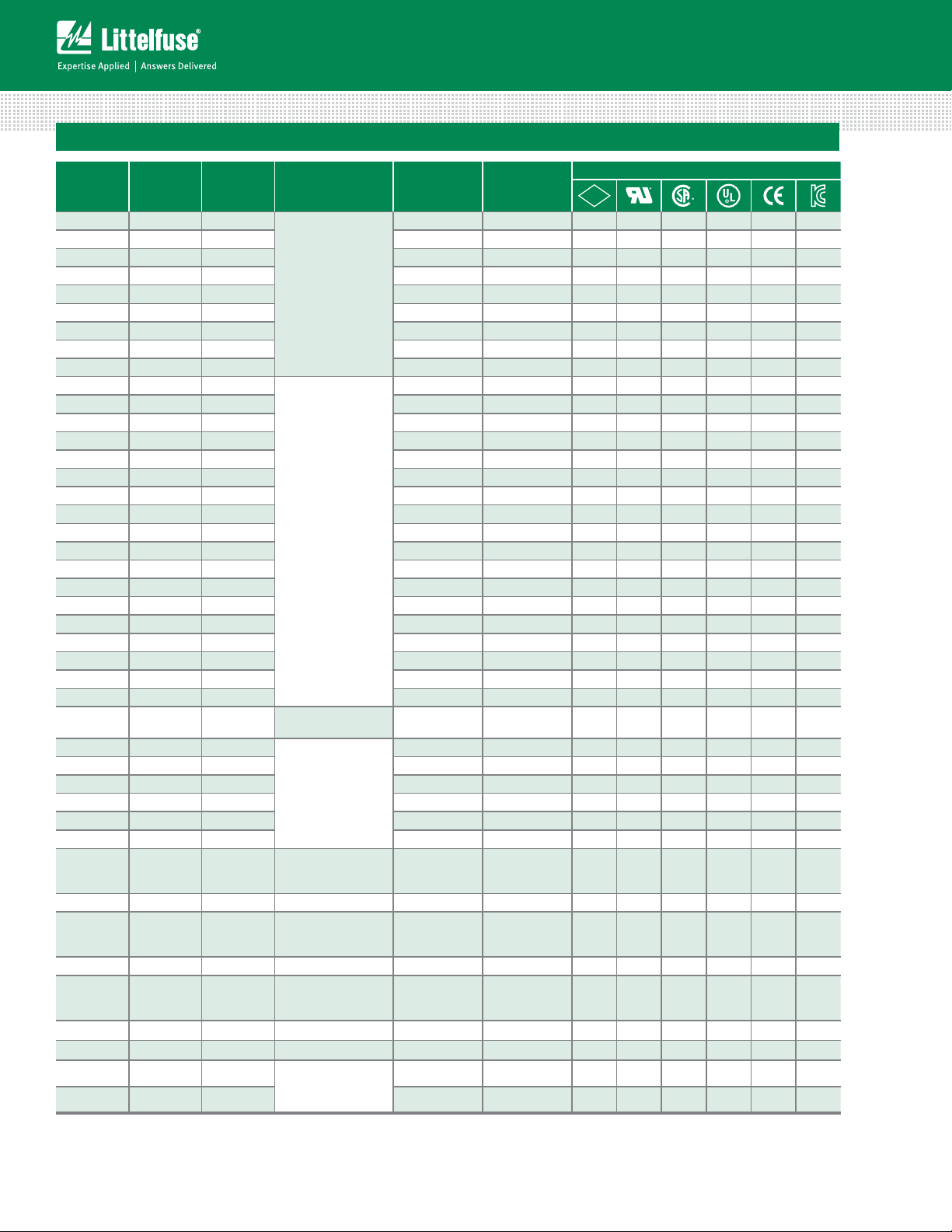
Electrical Characteristic Specifications by Item
Amp Code
Rating
(A)
.010 0.01 250
Ampere
Voltage
Rating
(V)
Interrupting
Rating
Nominal Cold
Resistance
(Ohms)
Nominal
Melting
2
t (A2 sec)
I
PS
E
3324.8000 0.00148 x
Agency Approvals
.031 0.031 250 332.5000 0. 0110 x
.062 0.062 250 91.7000 0.0276 x
.10 0 0.1 250 33.5500 0.0870 x
.125 0.125 250 22.4500 0.100 x
100A@250Vac
.150 0.15 250 15.4500 0.143 x
.175 0.175 250 8.9200 0.220 x
.187 0.187 250 7.7250 0.230 x
.200 0.2 250 6.7700 0.213 x
.250 0.25 250
4.4300 0.432 x x x
.300 0.3 250 3.2200 0.690 x x x
.375 0.375 250 2.1550 1.20 x x x
.400 0.4 250 1.9350 1.33 x x x
.500 0.5 250 1.3000 2.50 x x x
.600 0.6 250 0.9495 3.90 x x x
.700 0.7 250 0.7215 6.42 x x x
.750 0.75 250 0.6410 7. 0 0 x x x
.800 0.8 250 0.5725 8.20 x x x
0 01. 1 250 0.3890 16.3 x x x x
100A@250Vac
10KA@125Vac
10KA@125Vdc
01. 2 1. 2 250 0.2860 22.0 x x x x
1.25 1.25 250 0.2680 24.0 x x x x
01. 5 1. 5 250 0.1975 40.1 x x x x
01. 6 1. 6 250 0.1760 45.0 x x x x
002. 2 250 0.1210 80.0 x x x x
02.5 2.5 250 0.0835 136.0 x x x x x
02.8 2.8 250 0.0695 170.0 x x x x x
003. 3 250 0.0605 200.0 x x x x x
03.2 3.2 250
004. 4 250
100A@250Vac
10KA@125Vac
0.0539 214.0 x x x x x
0.0761 9.71 x x x x
005. 5 250 0.0522 25.0 x x x x
6.25 6.25 250 0.0346 60.4 x x x x
0 0 7. 7 250 0.0227 47.3 x x x x x
400A@250Vac
10KA@125Vac
008. 8 250 0.0193 67.1 x x x x x
010. 10 250 0.0132 137 x x x x x
400A@250Vac
012. 12 250
012.* 12 250
015. 15 250
015.* 15 250
020.
020.*
025.**
025.
20
20
25
25
250
250
250
250
030. 30 250 0.0019 1690 x x x x
*Higher i2t version available. Please add suffix “D” to part numbers. For instance, 0325020.MXDP, 0326020.MXDP
2
t test at 10× rated current.
I
2
t version available. Please add suffix “W” to part numbers. For instance, 0325025.MXWP
**Higher I
10KA@125Vac
600A@125Vdc
1500A@250Vac
400A@250Vac
10KA@125Vac
600A@125Vdc
1500A@250Vac
400A@250Vac
10KA@125Vac
600A@125Vdc
1500A@250Vac
1500A@250Vac
400A@250Vac
10KA@60Vdc
600A@125Vdc
0.0067 129 x x x x x
0.0011 445 x x x
0.0050 245 x x x x x
0.0083 760 x x x
0.0034 575 x x x x x
0.0042 2500
0.0032 4682
x x x
x x
0.0024 1030 x x x x
Specifications are subject to change without notice.
© 2013 Littelfuse, Inc.
Revised: 12/19/13
Page 3

Axial Lead & Cartridge Fuses
300
240
Temperature (°C) - Measured on bottom side of board
3AB > Time Lag > 325/326 Series
Temperature Rerating Curve
Average Time Current Curves
3.5A
2.5A
1.0A
3.0A
2.0A
1.5A
.750A
.375A
1000
100
10
1
TIME IN SECONDS
0.1
0.01
.500A
CURRENT IN AMPERES
4.0A
5.0A
6.25A
10
7.0A
8.0A
12.0A
10.0A
15.0A
20.0A
25.0A
30.0A
100 10000.1 10.05
Soldering Parameters - Wave Soldering
280
260
240
220
200
180
160
140
120
100
80
60
40
20
0
0
102030405060708090
Time (Seconds)
Preheat Time
100
110
120
130
140
150
160
170
180
190
200
210
220
Dwell Time
Cooling Time
Recommended Process Parameters:
Wave Parameter Lead-Free Recommendation
Preheat:
(Depends on Flux Activation Temperature)
Temperature Minimum:
Temperature Maximum:
Preheat Time: 60-180 seconds
Solder Pot Temperature:
Solder Dwell Time: 2-5 seconds
230
Recommended Hand-Solder Parameters:
Solder Iron Temperature: 350° C +/- 5°C
Heating Time: 5 seconds max.
(Typical Industry Recommendation)
100
° C
150
° C
260
° C Maximum
Note: These devices are not recommended for IR or
Convection Reflow process.
© 2013 Littelfuse, Inc.
Specifications are subject to change without notice.
Revised: 12/19/13
Page 4

Product Characteristics
326 000P Series
325 000P Series
Axial Lead Material:
0325 MX Pxxxx
Lead-free
Axial Lead & Cartridge Fuses
3AB > Time Lag > 325/326 Series
Materials
Cap: Nickel–plated brass
Leads: Tin–plated Copper
Body: Ceramic
Terminal Strength
Solderability
MIL-STD-202G, Method 211A,
Test Condition A
Reference IEC 60127 Second Edition
2003-01 Annex A
Cap1: Brand logo, current and voltage
Product Marking
ratings
Cap2: Series and agency approval
marks
Dimensions
Measurements displayed in millimeters (inches)
(cartridge)
6.35±0.3
(.25")
31.75±1.12
(1.25")
Axial Lead Diameter:
0.81±0.05 (.032") for
(0.01A - 15A)
1.02±0.06 (.040") for
(20A - 30A)
(axial leaded)
32.72±1.12
(1.288")
Axial Lead Length:
38.1±3.15 (1.50") TYP.
Tin-coated copper
6.985±0.3
(.275")
Operating Temperature –55ºC to +125ºC
MIL-STD-202G, Method 107G, Test
Thermal Shock
Condition B:(5 cycles - 65ºC to
125ºC)
Vibration: MIL-STD-202G, Method 201A
MIL-STD-202G, Method 103B, Test
Humidity
Condition A: High RH (95%) and
Elevated temperature(40ºC) for 240
hours
Salt Spray
MIL-STD-202G, Method 101D, Test
Condition B
Part Numbering System
Series
Amp Code
Refer to Amp Code column of
Electrical Characteristics Table
Quantity Code
M = 1000
Packaging Code
X = Filler
Packaging
Packaging Option Packaging Specification Quantity
325 Series
Bulk N/A 5 VX N/A
Bulk N/A 100 HX N/A
Bulk N/A 1000 MX N/A
Bulk N/A 1000 MX52 N/A
Bulk N/A 1000 MX52L N/A
Bulk N/A 1000 MXD N/A
Bulk N/A 1000 MXF31 N/A
Bulk N/A 1000 MXW N/A
326 Series
Bulk N/A 5 VX N/A
Bulk N/A 100 HX N/A
Bulk N/A 1000 MX N/A
Bulk N/A 1000 MXCC N/A
Bulk N/A 1000 MXD N/A
Quantity &
Packaging Code
Taping Width
Specifications are subject to change without notice.
© 2013 Littelfuse, Inc.
Revised: 12/19/13
 Loading...