

Page 1
Axial Lead & Cartridge Fuses
3AB > Very Fast-Acting > 322/332 Series
322/332 Series Lead-free 3AB, Very Fast-acting Fuse
Description
The 3AB Very Fast-Acting Fuse for protection of Silicon
Controlled Rectifiers and similar solid-state devices.
Features
PS
E
• InaccordancewithUL
Standard 248-14
• RoHScompliantand
Lead-free
• Availableincartridge
format only
Agency Approvals
Applications
Used as supplementary protection in appliance or
Agency Agency File Number Ampere Range
utilization equipment to provide individual protection for
components or internal circuits.
E10480
12A - 30A
Electrical Characteristics for Series
E10480 1A - 10A
% of Ampere
PS
E
NBK080306-
JP1021A/B
1A - 10A
1A - 30A
Rating
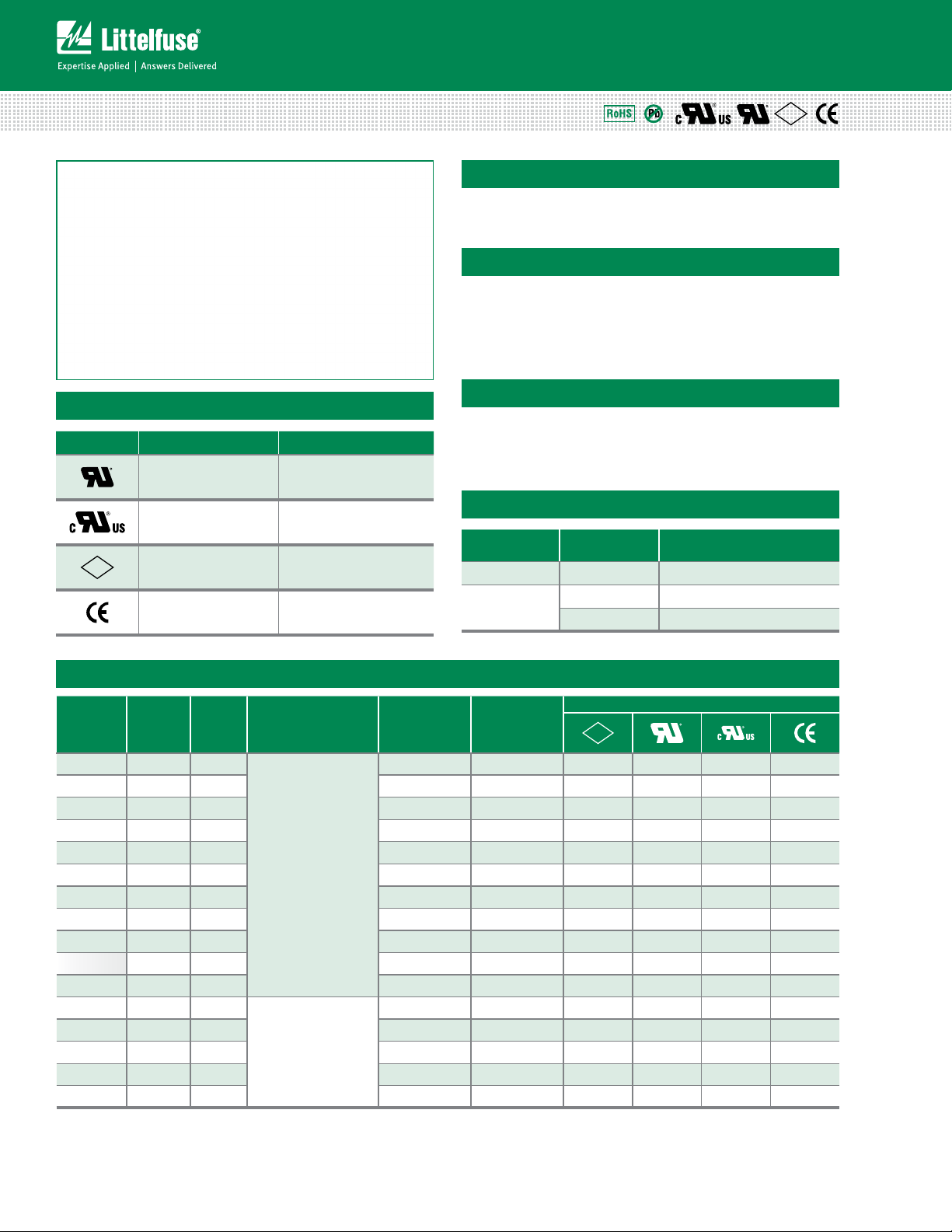
100% 1 – 30 4 hours, Minimum
250%
Ampere Rating Opening Time
1 – 10 .2 second, Maximum
12 – 30 1 sec.ond, Maximum.
Electrical Characteristic Specifications by Item
Amp Code
0 01. 1 250
1.25 1.25 250 0.0804 0.156 x x x
002. 2 250 0.0416 0.560 x x x
003. 3 250 0.0245 1.890 x x x
004. 4 250 0.0179 3.360 x x x
005. 5 250 0.0128 6.250 x x x
006. 6 250 0.0117 8.208 x x x
0 0 7. 7 250 0.0108 10.58 x x x
008. 8 250 0.0088 16.45 x x x
009. 9 250 0.0077 20.66 x x x
010. 10 250 0.0073 24.0 x x x
012. 12 65
015. 15 65 0.0043 90.0 x x
020. 20 65 0.0034 192.0 x x
025.* 25 65 0.0029 325.0 x x
030.* 30 65 0.0023 540.0 x x
* Ratings from 1A to 10A are available for 332 series
* Ratings from 12A to 30A are available for 322 series, these ratings are RoHS compliant version.
Ampere
Rating
(A)
Voltage
Rating
(V)
Interrupting
Rating
100A@250Vac
100A@125Vdc
200A@72Vdc
200A@65Vac
1000A@65Vdc
Nominal Cold
Resistance
(Ohms)
0.0927 0.100 x x x
0.0515 60.0 x x
Nominal
Melting
2
t (A2 sec)
I
PS
E
Agency Approvals
Specifications are subject to change without notice.
© 2013 Littelfuse, Inc.
Revised: 12/19/13
Page 2
Axial Lead & Cartridge Fuses
1
000
1/8A
1/4A
3/8A
1/2A
3/4A
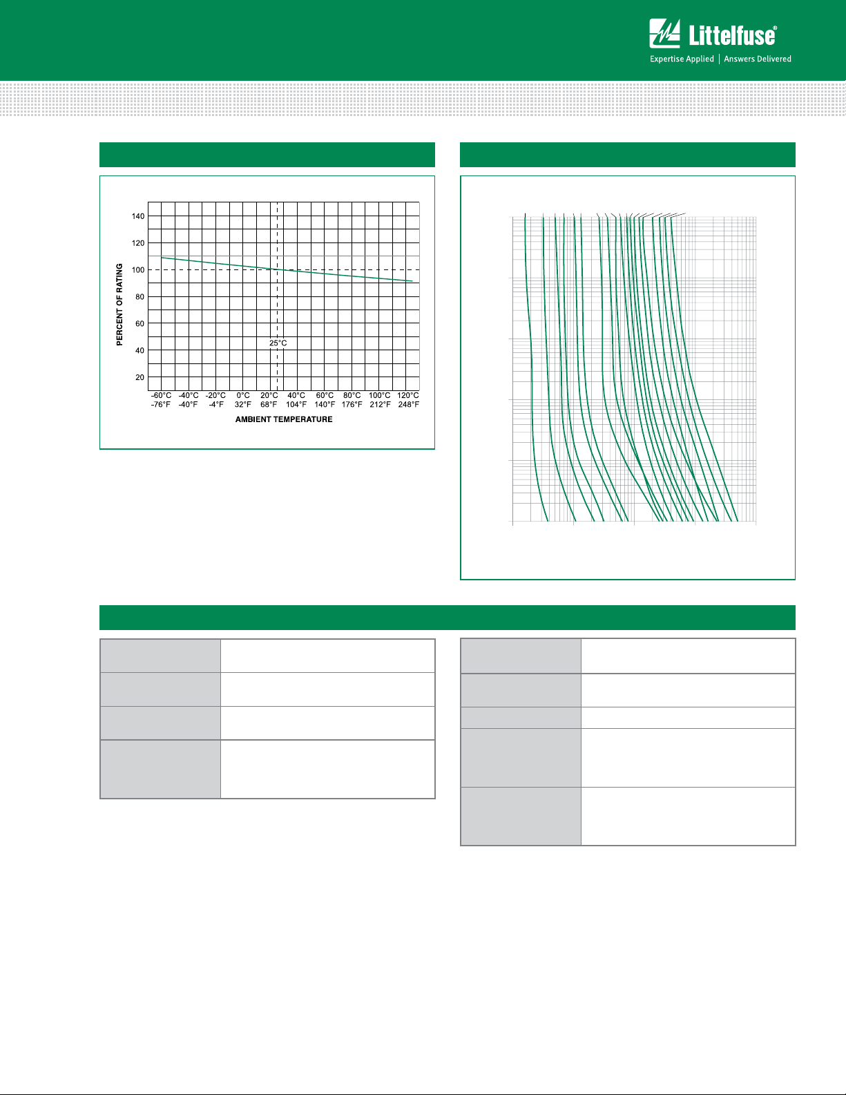
TIME IN SECONDS
CURRENT IN AMPERES
3AB > Very Fast-Acting > 322/332 Series
Average Time Current CurvesTemperature Rerating Curve
000
100
10
1
0.1
0.01
0.1 110100 1
1A2A3A4A5A6A7A8A10A
12A
15A
20A
25A
30A
Product CharacteristicsProduct Characteristics
Materials
Terminal Strength
Solderability
Product Marking
Body: Ceramic
Cap: Nickel–plated brass
MIL-STD-202G, Method 211A, Test
Condition A
Reference IEC 60127 Second Edition
2003-01 Annex A
Cap1: Brand logo, current and voltage
ratings
Cap2: Series and agency approval
marks
Operating
Temperature
Thermal Shock
–55ºC to +125ºC
MIL-STD-202G, Method 107G, Test
Condition B: (5 cycles -65°C to +125°C)
Vibration MIL-STD-202G, Method 201 A
MIL-STD-202G, Method 103B, Test
Humidity
Condition A: High RH (95%) and Elevated
temperature (40°C) for 240 hours
Salt Spray
MIL- STD-202G, Method 101D, Test
Condition B
© 2013 Littelfuse, Inc.
Specifications are subject to change without notice.
Revised: 12/19/13
Page 3

Axial Lead & Cartridge Fuses
3AB > Very Fast-Acting > 322/332 Series
Dimensions
Measurements displayed in millimeters (inches)
322 000P / 332 000P Series
(cartridge)
6.35±0.3
(.25")
31.75±1.12
(1.25")
Packaging
Packaging Option Packaging Specification Quantity
322 Series
Bulk N/A 1000 MX N/A
Bulk N/A 100 HX N/A
332 Series
Bulk N/A 100 HX N/A
Bulk N/A 1000 MX N/A
Part Numbering System
Series
Amp Code
Refer to Amp Code column of
Electrical Characteristics Table
Quantity Code
M = 1000
Packaging Code
X = Filler
Lead-free
Quantity &
Packaging Code
0322 MX Pxxxx
Reel Size
Additional Information
Datasheet
322 Series
Datasheet
332 Series
Resources
322 Series
Resources
332 Series
Samples
322 Series
Samples
332 Series
Specifications are subject to change without notice.
© 2013 Littelfuse, Inc.
Revised: 12/19/13
 Loading...