

Page 1
Axial Lead & Cartridge Fuses
PICO® ll > Very Fast-Acting > 263 Series
263 Series, PICO® II 250 Volt, Very Fast-Acting Fuse
Description
The PICO
axial leaded fuse that achieves a 250V rating in a small
package.
Features
®
II 263 Series Fuse is a specially designed
PS
E
Agency Approvals
Agency Agency File Number Ampere Range
E10480 62mA - 5A
PS
E
JET 1896-31007-1001 1A - 5A
LR 29862 125mA - 5A
Additional Information
Datasheet
Resources
Samples
Electrical Characteristics
• 250Vrating
• Veryfast–acting
• Smallsize
• Widerangeofcurrent
rating available (62mA to
5A)
• RoHScompliant&
Halogen-free
• Wideoperating
temperature range
• Lowtemperature
de-rating
Applications
• Lightingsystem
• Ofceautomation
• Powersupply
• LCD/PDPTV
• LCDmonitor
• Audio/Videosystem
• Medicalequipment
Electrical Characteristics
% of Ampere
Rating
100% 4 Hours, Min.
200% 1 Second, Max.
300% 0.1 Second, Max.
Opening Time
machines
Ampere
Rating
(A)
0.062 .062 250
0.125 .125 250 1.75 0.00251 0.3 x x
0.250 .250 250 0.715 0.0165 0.235 x x
0.375 .375 250 0.391 0.0444 0.195 x x
0.500 .500 250 0.332 0.084 0.302 x x
0.750 .750 250 0.150 0.0411 0.176 x x
1. 0 0 0 01. 250 0.105 0.087 0.165 x x x
1.50 01. 5 250 0.0635 0.398 0.148 x x x
2.00 002. 250 0.0444 0.74 0.137 x x x
2.50 02.5 250 0.0340 1.197 0.128 x x x
3.00 003. 250 0.0274 1.77 0.1225 x x x
3.50 03.5 250 0.0224 2.33 0.1175 x x x
4.00 004. 250 0.0193 3.08 0.1125 x x x
5.00 005. 250 0.0145 5.55 0.1065 x x x
Amp Code
Max
Voltage
Rating
(V)
Interrupting
Rating
50 amperes
at 250 VAC
PSE: 100
amperes
at 125 VAC.
Nominal Cold
Resistance
(Ohms)
5.50 0.000192 0.74 x
Nominal
Melting
2
t (A2 sec)
I
Nom
Voltage Drop
(mV)
Agency Approvals
PS
E
Specifications are subject to change without notice.
© 2013 Littelfuse, Inc.
Revised: 12/19/13
Page 2
Axial Lead & Cartridge Fuses
PICO® ll > Very Fast-Acting > 263 Series
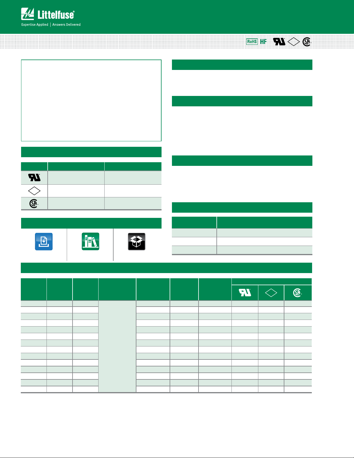
Temperature Rerating Curve
Note:
1. Derating depicted in this curve is in addition to the standard derating of 25% for
continuous operation.
Soldering Parameters
Recommended Process Parameters:
Wave Parameter Lead-Free Recommendation
Preheat:
(Depends on Flux Activation Temperature)
Temperature Minimum:
Temperature Maximum:
Preheat Time: 60-180 seconds
Solder Pot Temperature:
Solder Dwell Time: 2-5 seconds
(Typical Industry Recommendation)
100
° C
150
° C
260
° C Maximum
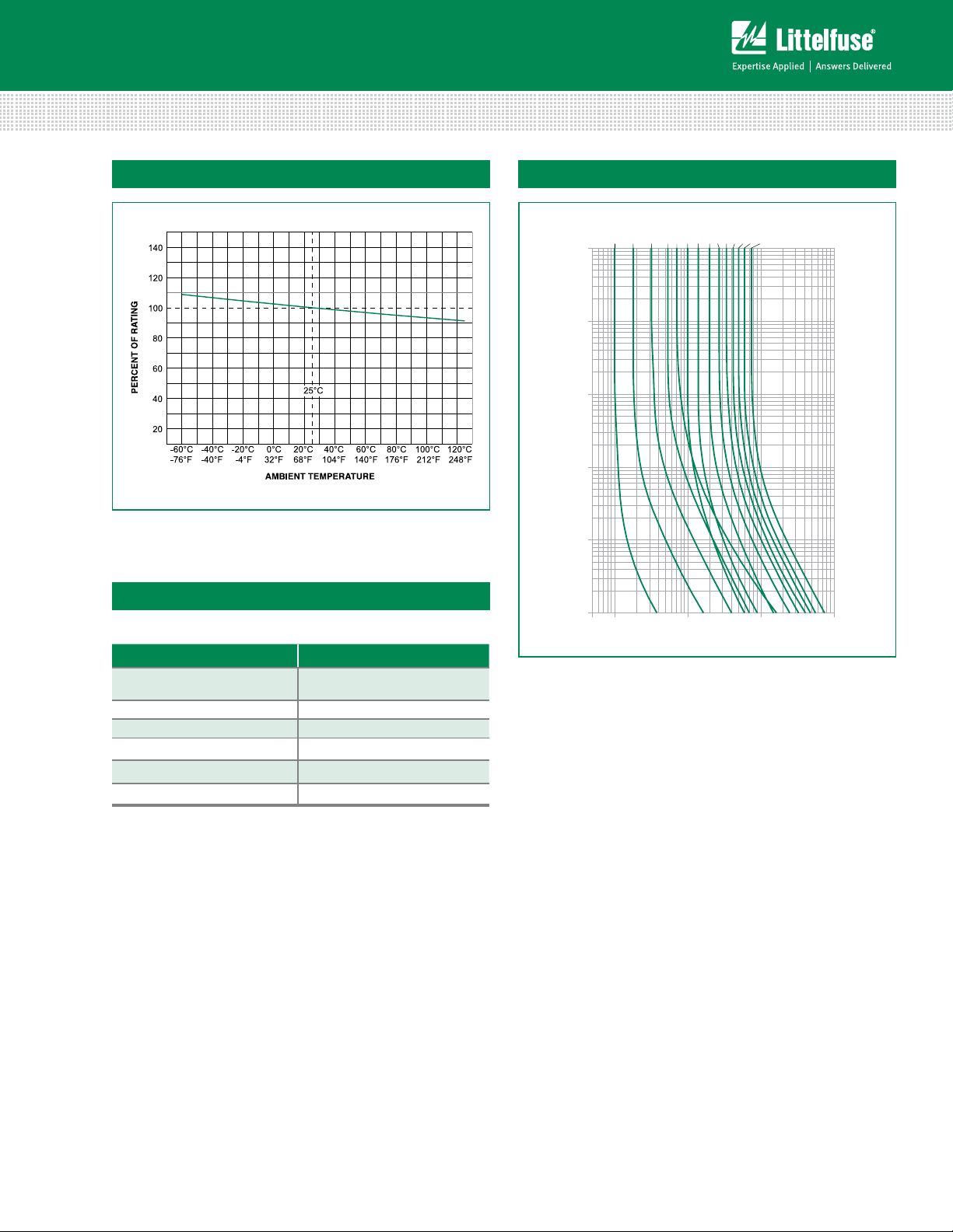
Average Time Current Curves
1/16A
1/8A
1/4A
3/8A
1/2A
100
10
1
TIME IN SECONDS
0.1
0.01
0.001
0.05 0.1 110 100
3/4A1A1 1/2A2A2 1/2A3A3 1/2A4A5A
CURRENT IN AMPERES
Recommended Hand-Solder Parameters:
Solder Iron Temperature: 350° C +/- 5°C
Heating Time: 5 seconds max.
Note: These devices are not recommended for IR or
Convection Reflow process.
© 2013 Littelfuse, Inc.
Specifications are subject to change without notice.
Revised: 12/19/13
Page 3

Product Characteristics
F
L
3 1/2 A
250 V
F
L
3 1/2 A
250 V
27.78
(1.094")
27.78
(1.094")
7.11 (.280")
62.7 (2.468")
52.4 (2.062")*
0.64 (.025")
3.94 (.16")
MAX
6.35 (.25")
tape
5.0 (.197")
6.35 (.25")
tape
0263 xxxx W R T1 L
Axial Lead & Cartridge Fuses
PICO® ll > Very Fast-Acting > 263 Series
Encapsulated, Epoxy-Coated
Body: Solder Coated Copper Leads.
Materials
RoHS compliant
Product: Pure Tin–coated Copper wire
leads
Solderability MIL-STD-202. Method 208.
Product Marking Body marking, current rating and logo
Operating
Temperature
Shock
–55ºC to +125ºC
MIL-STD-202, Method 213, Test Condition
I (100 G’s peak for 6 milliseconds)
Dimensions
MIL-STD-202, Method 201 (10–55
Vibration
Hz); MIL-STD-202, Method 204, Test
Condition C (55–2000 Hz at 10 G’s
Peak)
Salt Spray
Insulation Resistance
(After Opening):
Resistance to Soldering
Heat
Thermal Shock
MIL-STD-202, Method 101,
Test Condition B (48 hrs.)
MIL-STD-202, Method 302,
Test Condition A (10,000 ohms
minimum at 100 volts)
MIL-STD-202, Method 210,
Test Condition C (10 sec. at 260ºC)
MIL-STD-202, Method 107, Test
Condition B (–55ºC to 125ºC)
Moisture Resistance MIL-STD-202, Method 106
MIL-STD-202, Method 211,
Lead Pull Force
Test Condition A (will withstand 7 lb.
axial pull test)
Part Numbering System
Series
Current Rating
Refer to Amp Code column of
Electrical Characteristics Table
Quantity
W = 3000
M = 1000
H = 100
Type of Packaging
R = Reel
A = Ammo Pack
X = Loose Pack
Lead Length
T1: 52.4mm (2.062”)*
RoHS + HF
Packaging
Packaging Option Packaging Specification Quantity
T1: 52.4mm (2.062”)
Tape and Reel
Notes: * T1 dimension is defined as the length of the component between the two tapes. The full component length is 62.7mm (2.468").
EIA 296
Please refer to available quantities
above in “Part Numbering System”
Quantity &
Packaging Code
Specifications are subject to change without notice.
© 2013 Littelfuse, Inc.
Revised: 12/19/13
 Loading...