

Page 1
Varistor Products
Radial Lead Varistors > UltraMOVTM 25S Series
UltraMOVTM 25S Varistor Series
Agency Approvals
Agency Agency FIle Number Status
E320116 Approved
091788 Approved
RoHS
Description
The UltraMOVTM 25S Varistor Series is designed for
applications requiring high peak surge current ratings and
high energy absorption capability. UltraMOV™ varistors are
primarily intended for use in AC Line Voltage applications
such as Surge Protective Devices (SPD), Uninterruptable
Power Supplies (UPS), AC Power Taps, AC Power Meters,
or other products that require voltage clamping of high
transient surge currents from sources such as lightning,
inductive load switching, or capacitor bank switching.
These devices have 25mm square forms are produced
in a radial lead package and offered with straight leads.
UltraMOVs are manufactured with recognized epoxy
encapsulation and are rated for ambient temperatures
up to 85°C with no derating. This 25S Series is
LASER-branded and is supplied in bulk packaging.
Features
• Lead–free and
RoHS compliant.
• High peak surge
current rating (I
)
TM
22kA, single 8/20μs
pulse, (25mm)
• 40kA rating when 2
devices paralleled
(VN(DC) matched
within +/- 5%,
contact factory for
special selections
• Standard operating
voltage range
compatible with
common AC line
voltages (115 to
750VAC)
• Characterized for
maximum standby
current (Leakage)
• Custom voltage
types available
• Standard lead form
and lead space options
25S Series
™
UltraMOV
Absolute Maximum Ratings
• For ratings of individual members of a series, see Device Ratings and Specifications chart
Continuous UltraMOVTM 25S Series Units
Steady State Applied Voltage:
AC Voltage Range (V
DC Voltage Range (V
Transients:
Peak Pulse Current (ITM) 8x20μs Current Wave Single Pulse 22,000 A
Single-Pulse Energy Capability (W
Operating Ambient Temperature Range (T
Storage Temperature Range (T
Temperature Coefficient (aV) of Clamping Voltage (VC) at Specified Test Current <0.01 %/C
Hi-Pot Encapsulation (COATING Isolation Voltage Capability)
Dielectic Withstand DC for 1 min per MIL–STD–202, Method 301
Insulation Resistance of the Epoxy Coating 1000 MΩ
CAUTION: Stresses above those listed in "Absolute Maximum Ratings" may cause permanent damage to the device. This is a stress only
rating and operation of the device at these or any other conditions above those indicated in the operational sections of this specification is
not implied.
© 2013 Littelfuse, Inc.
Specifications are subject to change without notice.
Please refer to www.littelfuse.com/series/ultramov25s.html for current information.
) -55 to +125 ºC
STG
) 115 to 750 V
M(AC)RMS
) 150 to 970 V
M(DC)
) 2ms Current Wave 230 to 890 J
) -55 to +85 ºC
A
TM
2500 V
107
Revised: May 8, 2013
UltraMOV™ 25S Varistor Series
Page 2
Varistor Products
Radial Lead Varistors > UltraMOVTM 25S Series
UltraMOV™ 25S Series Ratings & Specifications
Maximum Rating (85°C) Specifications (25°C)
Part
Number
Branding
Continuous Transient
AC Volts DC Volts
V
M(AC)RMSVM(DC)
Energy
2ms
W
TM
1 x
Pulse
Peak Surge
Current
8 x 20μs
ITM
1 x Pulse
Varistor Voltage
at 1mA DC
Test Current
V
NOM
Min
V
NOM
Max
(V) (V) (J) (A) (V) (V) (pF)
V25S115P P25S115 115 150 230 22000 162 198 295 400 4500
V25S130P P25S130 130 170 255 22000 184 226 335 500 3900
V25S140P P25S140 140 180 285 22000 200 240 355 500 3500
V25S150P P25S150 150 200 300 22000 216 264 390 500 3200
V25S175P P25S175 175 225 315 22000 243 297 450 600 2550
V25S230P P25S230 230 300 400 22000 324 396 585 700 1900
V25S250P P25S250 250 320 435 22000 351 429 640 800 1750
V25S275P P25S275 275 350 470 22000 387 473 700 900 1610
V25S300P P25S300 300 385 500 22000 423 517 765 1000 1450
V25S320P P25S320 320 420 540 22000 459 561 825 1000 1350
V25S385P P25S385 385 505 630 22000 558 682 1010 1200 108 0
V25S420P P25S420 420 560 655 22000 612 748 1100 1500 1000
V25S440P P25S440 440 585 675 22000 643 787 1160 n/a 900
V25S460P P25S460 460 615 690 22000 675 825 1220 n/a 870
V25S510P P25S510 510 670 700 22000 738 902 1335 n/a 820
V25S550P P25S550 550 745 765 22000 819 1001 1475 n/a 750
V25S625P P25S625 625 825 800 22000 900 1100 1625 n/a 660
V25S750P P25S750 750 970 890 22000 1080 1320 1950 n/a 550
Note: Average powder dissipation of transients should not exceed 1.5 watts.
Maximum
Clamping
Voltage at 100A,
8 x 20μs
V
C
UL 1449 ed.3
Voltage
Protection
Rating
VPR C
Typical
Capaci-
f = 1MHz
tance
Transient V-I Characteristics Curves
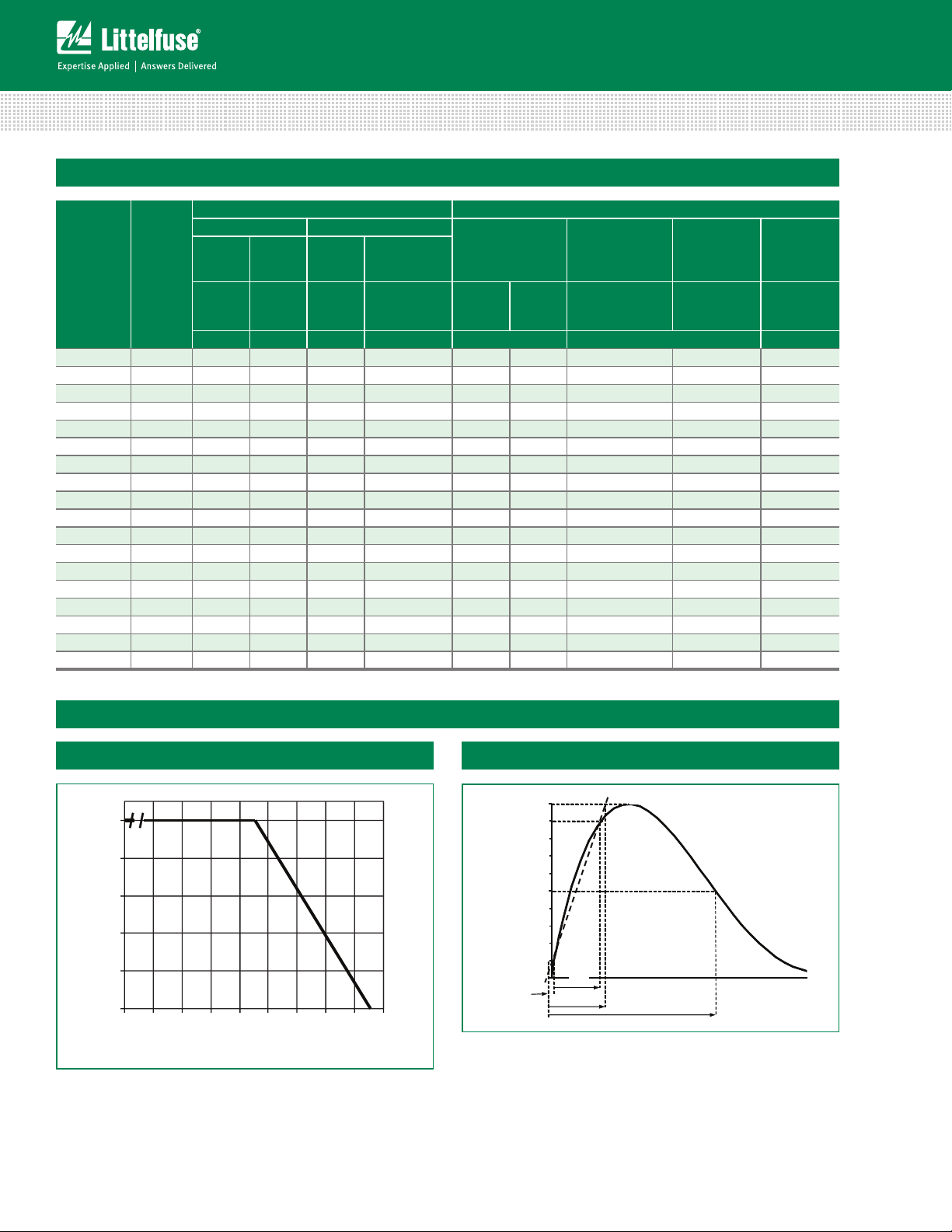
Peak Current, Energy and Power Derating Curve
100
80
60
40
20
PERCE NT OF RATED V ALUE
0
Figure 1
55 50 60 70 80 90 100 110 120 130
AMBIENT T EMPERATUR E (ºC)
For applications exceeding 85ºC ambient temperature, the
peak surge current and energy ratings must be reduced as
shown above.
UltraMOV™ 25S Varistor Series
Peak Pulse Current Test Waveform for Clamping Voltage
108
Revised: May 8, 2013
100
50
PERCENT OF PEAK VALUE
0
t
t
1
t
2
Figure 2
O
1
01 = Virtual Origin of Wave
T = Time from 10% to 90% of Peak
T1 = Rise Time = 1.25 x T
T2 = Decay Time
Example - For an 8/20 μs Current Waveform:
8μs = T1 = Rise Time
20μs = T2 = Decay Time
Please refer to www.littelfuse.com/series/ultramov25s.html for current information.
Specifications are subject to change without notice.
TIME
© 2013 Littelfuse, Inc.
Page 3

Varistor Products
Radial Lead Varistors > UltraMOVTM 25S Series
V-I Limit Curves
10000
1000
385
420
440
460
510
550
625
750
Maximum Peak Voltage (V)
100
0.00001 0.0001 0.001 0.01 0.1 1 10 100 1000 10000 100000
Figure 3
Pulse Rating Curves
100000
10000
1000
100
Peak Current (A)
10
10
10
10
10
320
300
275
250
25S Series
™
115
140
130
P eak C u rren t (A)
150
175 230
UltraMOV
1
2
15
2
3
4
5
6
∞
10
1
Figure 4
© 2013 Littelfuse, Inc.
Specifications are subject to change without notice.
Please refer to www.littelfuse.com/series/ultramov25s.html for current information.
10 100 1000 10000
Impulse Duration (μs)
109
Revised: May 8, 2013
UltraMOV™ 25S Varistor Series
Page 4

Wave Solder Profile
TEMPERATURE
(
C)
TEMPERATURE
(ºC)
Varistor Products
Radial Lead Varistors > UltraMOVTM 25S Series
Non Lead–free Wave Solder Profile
300
250
º
200
150
100
50
0
00.5 11.5 22.5 33.5 4
Figure 5 Figure 6
Maximum Wave 240C
TIME(MINUTE
S)
Lead–free Wave Solder Profile
300
250
200
150
100
50
0
00.511.522.533.54
TIME(MINUTES)
Physical Specifications Environmental Specifications
Lead Material Copper Clad Steel Wire
Soldering
Characteristics
Insulating Material
Device Labeling
Solderability per MIL–STD–202,
Method 208E
Cured, flame retardant epoxy polymer
meets UL94V–0 requirements
Marked with LF, voltage, UL/CSA Logos,
and date code
Operating/Storage
Temperature
Passive Aging
Humidity Aging
Thermal Shock
Maximum Wave 260C
-55°C to +85°C/
-55°C to +125°C
+85°C, 1000 hours
+/-10% typical voltage change
+85°C, 85% RH, 1000 hours
+/-10% typical voltage change
+85°C to -40°C 5 times
+/-10% typical voltage change
Solvent Resistance MIL–STD–202, Method 215F
Moisture Sensitivity Level 1, J–STD–020C
UltraMOVTM 25S Series Varistors for High-Temperature Operating Conditions:
Phenolic coated devices are available with improved maximum operating temperature 125ºC.
These devices also have improved temperature cycling capability. Ratings and specifications
are per standard series except Hi–Pot Encapsulation (Isolation Voltage Capability) = 500V.
To order: add 'X1347' to part number (e.g. V25S150PX1347). These devices are NOT UL, CSA,
CECC or VDE certified.Contact factory for further details.
UltraMOV™ 25S Varistor Series
110
Revised: May 8, 2013
Please refer to www.littelfuse.com/series/ultramov25s.html for current information.
Specifications are subject to change without notice.
© 2013 Littelfuse, Inc.
Page 5

Varistor Products
Radial Lead Varistors > UltraMOVTM 25S Series
Product Dimensions (mm)
b
D
e
e1
A
maxb minb maxD maxe mine max
V25S115P
V25S130P 1.6 2.9 5.9
V25S140P 1.7 3.0 6.0
V25S150P 1.8 3.1 6.1
V25S175P 1.9 3.3 6.3
V25S230P 2.0 3.4 6.4
L A
E
V25S250P 2.1 3.5 6.5
V25S275P 2.3 3.7 6.7
V25S300P 2.4 3.9 6.9
V25S320P 2.6 4.1 7.1
V25S385P 3.0 4.7 7.7
V25S420P 3.3 5.0 8.0
V25S440P 3.4 5.2 8.2
V25S460P 3.6 5.4 8.4
V25S510P 1.6 3.4 8.7
V25S550P 1.9 3.9 9.2
V25S625P 2.3 4.3 9.6
V25S750P 3.1 5.4 10.7
32.5 0.95 1.05 28 11.7 13.7
e1
min
1.5 2.7 5.7
e1
maxE maxL min
25.4
25S Series
™
Notes
1. Additional optional lead form, packaging and lead spacing requirements are subject to availability and to minimum
order requirements. Please contact factory for details.
2. Nickel Barrier Wire option (Suffix 'X2855')Standard parts use Tin-Coated Copper wire. Nickel Barrier Coated Wire
is available as an option. This is Copper Wire with a flashing of Nickel, followed by a top coat of Tin. To order please
add suffix 'X2855' to end of standard part number. Contact factory for more details if required.
3. UltraMOV 25S have been qualified as type 1 application by UL1449 edition 3, which allows Permanant Connection
between the secondary of the service transformer and the line side of the service equipment overcurrent device,
as well as the load side, including watt-hour meter socket enclosures and intended to be installed without an
external overcurrent protective device.
UltraMOV
© 2013 Littelfuse, Inc.
Specifications are subject to change without notice.
Please refer to www.littelfuse.com/series/ultramov25s.html for current information.
111
Revised: May 8, 2013
UltraMOV™ 25S Varistor Series
 Loading...