

Page 1
Axial Lead & Cartridge Fuses
5×20 mm > Medium-Acting > 233 Series
233 Series, 5×20 mm, Medium-Acting Fuse
PS
E
Description
5×20mm medium–acting glass body fuse designed to UL
specification.
Features
Agency Approvals
Agency Agency File Number Ampere Range
Cartridge Certificates:
NBK190609-JP1021A
PS
E
NBK030609-JP1021B
Leaded Certificates:
NBK190609-JP1021B
NBK030609-JP1021D
Certificates:
SU05001 – 2010
Listed File:
E10480
Guide:
JDYX
Fle:
029862
Acc. Class:
LR1422-01
1A – 10A
1A – 5A
6A – 10A
1A – 5A
6A – 10A
1A – 6.5A
1A – 10A
1A – 6A
8A – 10A
• DesingedtoUL/CSA/
ANCE 248 Standard
• RoHScompliantand
lead-free
• Availableincartridgeand
axial lead format
Applications
Used as supplementary protection in appliance or
utilization equipment to provide individual protection for
components or internal circuits.
Electrical Characteristics for Series
% of Ampere
Rating
100%
135%
200%
Ampere
Rating
1A – 3.5A 4 hours, Minimum
4A – 7A 1 hour, Minimum
8A – 10A 1 hour, Minimum
1A – 3.5A 15 sec., Min; 1500 sec., Max.
4A – 7A 15 sec., Min; 1500 sec., Max.
8A – 10A 3 sec., Min; 3600 sec., Max.
1A – 3.5A .60 sec., Min; 3 sec., Max.
4A – 7A .60 sec., Min; 3 sec., Max.
8A – 10A 0.4 sec., Min; 2.25 sec., Max.
Opening Time
Electrical Characteristic Specifications by Item
Amp Code
0 01. 1 125
1.25 1.25 125 0.1263 3.39000 x x x x x
01. 6 1. 6 125 0.0880 6.14000 x x x x x
002. 2 125 0.0684 9.97000 x x x x x
02.5 2.5 125 0.0521 17.04500 x x x x x
003. 3 125 0.0431 26.24000 x x x x x
3.15 3.15 125 0.0380 29.79500 x x x x x
03.5 3.5 125 0.0322 36.27500 x x x x x
004. 4 125 0.0293 51.61000 x x x x x
005. 5 125 0.0217 89.97500 x x x x x
006. 6 125 0.0179 131.45500 x x x x x
06.3 6.3 125 0.0166 151.90500 x x x x x
007. 7 125 0.0137 157.31000 x x x
008. 8 125 0.0084 169.43500 x x x x
010. 10 125 0.0066 274.11500 x x x x
© 2013 Littelfuse, Inc.
Specifications are subject to change without notice.
Revised: 12/19/13
Amp
Rating
(A)
Voltage
Rating
(V)
Interrupting
Rating
10,000A @ 125 VAC
Nominal Cold
Resistance
(Ohms)
0.1750 1.97500 x x x x x
Nominal Melting
2
t
I
(A2 sec)
Agency Approvals
PS
E
Page 2
Axial Lead & Cartridge Fuses
300
240
Temperature (°C) - Measured on bottom side of board
5×20 mm > Medium-Acting > 233 Series
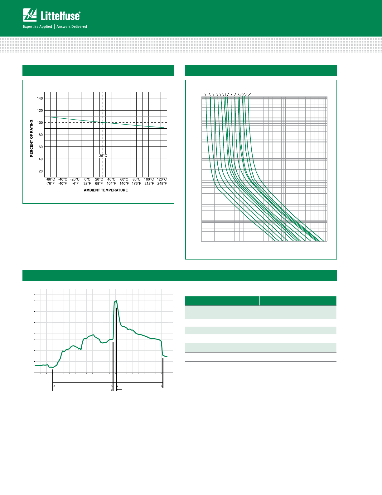
Average Time Current CurvesTemperature Rerating Curve
1A
1.25A
1.6A2A2.5A3A3.15A
10000
1000
100
TIME IN SECONDS
3.5A4A5A6A6.3A7A8A
10A
0.1
0.01
0.001
110100 1000
CURRENT IN AMPERES
Soldering Parameters - Wave Soldering
280
260
240
220
200
180
160
140
120
100
80
60
40
20
0
0
102030405060708090
Time (Seconds)
Preheat Time
100
110
120
130
140
150
160
170
180
190
200
210
220
Dwell Time
Cooling Time
Recommended Process Parameters:
Wave Parameter Lead-Free Recommendation
Preheat:
(Depends on Flux Activation Temperature)
Temperature Minimum:
Temperature Maximum:
Preheat Time: 60-180 seconds
Solder Pot Temperature:
Solder Dwell Time: 2-5 seconds
Recommended Hand-Solder Parameters:
230
Solder Iron Temperature: 350° C +/- 5°C
Heating Time: 5 seconds max.
(Typical Industry Recommendation)
100
° C
150
° C
260
° C Maximum
Note: These devices are not recommended for IR or
Convection Reflow process.
Specifications are subject to change without notice.
© 2013 Littelfuse, Inc.
Revised: 12/19/13
Page 3

Axial Lead & Cartridge Fuses
5×20 mm > Medium-Acting > 233 Series
Product Characteristics
Materials
Terminal Strength
Solderability
Product Marking
Packaging
Dimensions
Body: Glass
Cap: Nickel–plated brass
Leads: Tin–plated Copper
MIL-STD-202G, Method 211A, Test
Condition A
Reference IEC 60127 Second Edition
2003-01 Annex A
Cap 1: Brand logo, current and voltage
rating
Cap 2: Series and agency approval
markings
Available in Bulk (M=1000 pcs/pkg) or on
Tape/Reel (MRET1=1000 pcs/reel)
0233 000P
20+0.5
5.2+0.1
-0.2
5.1+0.6
5.1+0.6
0233000XEP
40
.65*
22.5 MAX
5.8 MAX
Operating Temperature –55ºC to +125ºC
MIL-STD-202G, Method 107G, Test
Thermal Shock
Condition B: (5 cycles –65ºC to
+125ºC)
Vibration MIL-STD-202G, Method 201A
MIL-STD-202G, Method 103B, Test
Humidity
Condition A. high RH (95%) and
elevated temp (40ºC) for 240 hours
Salt Spray
MIL-STD-202G, Method 101D, Test
Condition B
Part Numbering System
0233 MX Pxxxx
Series
Amp Code
Refer to Amp Code column of
Electrical Characteristics Table
Quantity Code
M = 1000
Packaging Code
X = Filler
Lead-free
Notes:
* Ratings above 6.3A
have 0.8 mm dia lead
All dimensions in mm
Packaging
Packaging Option Packaging Specification Quantity
233 Series
Bulk N/A 1000 MX N/A
Bulk N/A 1000 MXE N/A
Reel and Tape EIA 296-E 1000 MRET1 T1=53mm (2.087”)
Bulk N/A 1000 MXB N/A
Quantity &
Packaging Code
Additional Information
© 2013 Littelfuse, Inc.
Specifications are subject to change without notice.
Revised: 12/19/13
Datasheet
Resources
Taping Width
Samples
 Loading...