

Axial Lead & Cartridge Fuses
5×20 mm > Time-Lag > 218 Series
218 Series, 5×20 mm, Time-Lag (Slo-Blo®) Fuse
Description
5×20mm Time-Lag glass body cartridge fuse designed to
IEC specification.
Features
PS
E
Agency Approvals
Agency Agency File Number Ampere Range
Cartridge Certificates:
NBK090205-E10480A
NBK120802-E10480C
PS
E
Leaded Certificates:
NBK090205-E10480B
NBK120802-E10480D
Certificates:
* Approval for Cartridge versions only
2005010207145715
Certificates:
SU05001-3005
SU05001-2008
SU05001-2009
Recognised File:
E10480
Guide:
JDYX2
File:
029862
Acc. Class:
LR1422-30
File:
9850004, 9843043,
1309488, 304650, 416270
License:
40013496
License:
40016604
License:
KM 41462
1A – 5A
6.3A – 15A
1A – 5A
6.3A – 15A
32mA – 6.3A
32mA – 40mA
50mA – 800mA
1A – 10A
32mA – 16A
32mA – 15A
32mA – 6.3A
32mA – 10A
15A*
80mA – 6.3A
32mA – 16A
• DesignedtoInternational
(IEC ) Standards for use
globally
• MeetstheIEC60127-2,
• Availableincartridgeand
axial lead form
• RoHScompliantand
lead-free
Sheet 3 specification for
Time-Lag fuses
Applications
Used as supplementary protection in appliance or
utilization equipment to provide individual protection for
components or internal circuits.
Additional Information
Datasheet
Resources
Samples
Electrical Characteristics
% of Ampere
Rating
150%
210%
275%
400%
1000%
Ampere Rating Opening Time
32mA–100mA
125mA-6.3A
8A-15A
32mA-100mA 120 sec., Maximum
125mA-6.3A 120 sec., Maximum
8A-15A 120 sec., Maximum
32mA-100mA 200 ms., Min.; 10 sec. Max.
125mA-6.3A 600 ms., Min.; 10 sec. Max.
8A-15A
32mA-100mA
125mA-6.3A
8A-15A
32mA-100mA 10 ms., Min.; 300 ms. Max.
125mA-6.3A 20 ms., Min.; 300 ms. Max.
8A-15A
60 minutes, Minimum
60 minutes, Minimum
30 minutes, Minimum
600 ms., Min.; 10 sec. Max.
40 ms., Min.; 3 sec. Max.
150 ms., Min.; 3 sec. Max.
150 ms., Min.; 3 sec. Max.
20 ms., Min.; 300 ms. Max.
© 2013 Littelfuse, Inc.
Specifications are subject to change without notice.
Revised: 12/19/13
PS
E
Electrical Characteristics
Axial Lead & Cartridge Fuses
5×20 mm > Time-Lag > 218 Series
Amp
Rating
(A)
Voltage
Rating
Amp
Code
.032 0.032 250
(V)
Interrupting
Rating
Nominal
Cold
Resistance
(Ohms)
Nominal
Melting
2
t (A2 sec)
I
Maximum
Voltage Drop
at Rated
Current
(mV)
Maximum
Dissipation
48.2580 0.01100 5000 1. 6
Power
At
1.5ln(W)
x x x x x x x
Agency Approvals
.040 0.04 250 31.8620 0. 01100 4000 1. 6 x x x x x x x
.050 0.05 250 21.2920 0.01700 3500 1. 6 x x x x x x x
.063 0.063 250 14.2680 0.02800 3000 1.6 x x x x x x x
.080 0.08 250 9.0700 0.07500 2500 1. 6 x x x x x x x x
.10 0 0.1 250 6.0180 0.07900 2000 1. 6 x x x x x x x x
.125 0.125 250 4.2000 0.1465 1900 1. 6 x x x x x x x x
.160 0.16 250 3.7000 0.14400 1500 1.6 x x x x x x x x
.200 0.2 250 1.6000 0.3410 13 00 1. 6 x x x x x x x x
.250 0.25 250 1.0495 0.5405 110 0 1.6 x x x x x x x x
.315 0.315 250 0.8475 1. 110 0 1000 1. 6 x x x x x x x x
35 A @ 250 VAC
.400 0.4 250 0.5350 1.3250 900 1. 6 x x x x x x x x
.500 0.5 250 0.3700 2.8250 300 1. 6 x x x x x x x x
.630 0.63 250 0.2750 4.6750 250 1. 6 x x x x x x x x
.800 0.8 250 0.0813 3.370 150 1. 6
x x x x x x x x
0 01. 1 250 0.0613 6.730 150 1.6 x x x x x x x x x
1.25 1.25 250 0.0446 12.650 150 1. 6 x x x x x x x x x
01. 6 1. 6 250 0.0336 23.350 150 1. 6 x x x x x x x x x
002. 2 250 0.0293 14.450 150 1. 6 x x x x x x x x x
02.5 2.5 250 0.0219 23.250 120 1. 6 x x x x x x x x x
3.15 3.15 250 0.0173 38.150 10 0 1. 6 x x x x x x x x x
004. 4 250
005. 5 250
06.3 6.3 250
008. 8 250
010. 10 250
12.5 12.5 250
015. 15 250
016. 16 250
* Approval for cartidge versions only
40 A @ 250 VAC
50 A @ 250 VAC
63 A @ 250 VAC
80 A @ 250 VAC
100 A @ 250 VAC
63 A @ 250 VAC
100 A @ 250 VAC
63 A @ 250 VAC
0.0129 69.10 100 1. 6 x x x x x x x x x
0.0104 111.0 0 100 1.6 x x x x x x x x x
0.0076 198.50 10 0 1. 6 x x x x x x x x x
0.0059 341.50 100 4 x x x x x x
0.0045 568.00 10 0 4 x x x x x x
0.0034 889.00 10 0 4
0.0028 1405.00 10 0 4
0.0021 1955.00 10 0 4
x x x
x x x x x*
x x
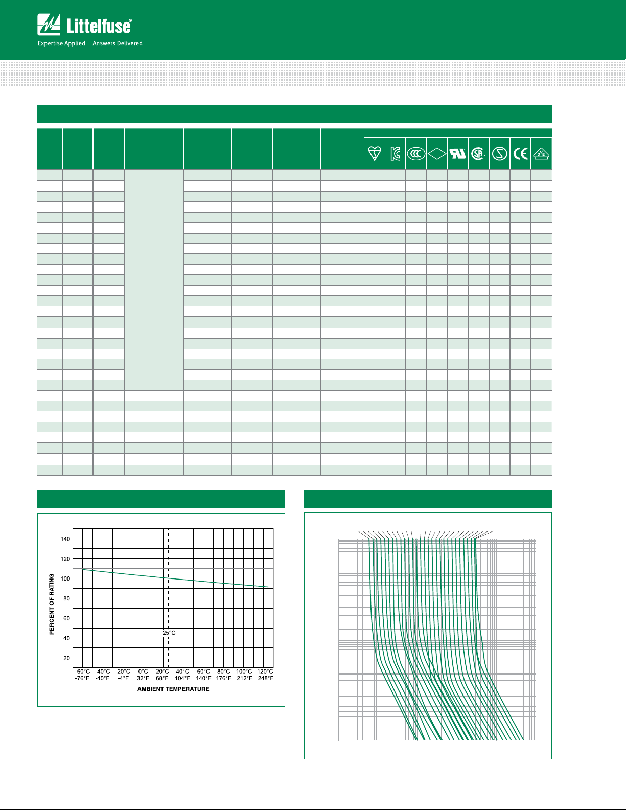
Temperature Rerating Curve
Average Time Current Curves
0.032A
0.040A
0.050A
0.063A
0.080A
0.100A
0.125A
0.160A
0.200A
0.250A
0.315A
0.400A
0.500A
0.630A
0.800A1A1.25A
10000
1000
100
10
TIME IN SECONDS
1
0.1
0.01
0.01 0.1 1 10 100
CURRENT IN AMPERES
1.6A2A2.5A
Specifications are subject to change without notice.
3.15A4A5A
6.3A8A10A
12.5A
15A
16A
© 2013 Littelfuse, Inc.
Revised: 12/19/13

Axial Lead & Cartridge Fuses
300
240
Temperature (°C) - Measured on bottom side of board
5×20 mm > Time-Lag > 218 Series
Soldering Parameters - Wave Soldering
280
260
240
220
200
180
160
140
120
100
80
60
40
20
0
0
102030405060708090
Time (Seconds)
Preheat Time
Product Characteristics
Material
Terminal Strength
Solderability
Product Marking
Packaging
100
110
120
130
140
150
160
170
180
190
200
210
220
Dwell Time
Cooling Time
Body: Glass
Cap: Nickel–plated Brass
Leads: Tin–plated Copper
MIL-STD-202G, Method 211A, Test
Condition A
Reference IEC 60127 Second
Edition 2003-01 Annex A
Cap1: Brand logo, current and
voltage ratings
Cap2: Agency approval marks
Available in Bulk (M=1000 pcs/pkg)
or on Tape/Reel (MRET1=1000 pcs/
reel)
Recommended Process Parameters:
Wave Parameter Lead-Free Recommendation
Preheat:
(Depends on Flux Activation Temperature)
Temperature Minimum:
Temperature Maximum:
(Typical Industry Recommendation)
100
° C
150
° C
Preheat Time: 60-180 seconds
Solder Pot Temperature:
260
° C Maximum
Solder Dwell Time: 2-5 seconds
Recommended Hand-Solder Parameters:
230
Solder Iron Temperature: 350° C +/- 5°C
Heating Time: 5 seconds max.
Note: These devices are not recommended for IR or
Convection Reflow process.
Operating Temperature –55ºC to +125ºC
Thermal Shock
Vibration MIL-STD-202G, Method 201A
Humidity
Salt Spray
MIL-STD-202G, Method 107G, Test
Condition B (5 cycles, –65
+125°C)
MIL-STD-202G, Method 103B, Test
Condition A (High RH (95%) and
elevated temperature (40
hours)
MIL-STD-202G, Method 101D, Test
Condition B
°
C to
°
C) for 240
© 2013 Littelfuse, Inc.
Specifications are subject to change without notice.
Revised: 12/19/13

Axial Lead & Cartridge Fuses
0218 000P
20+0.5
5.1+0.6
5.2+0.1
-0.2
5.1+0.6
40
22.5 MAX
5.8 MAX
0218016. XEP
0218.125 XEP
to
0218.100XEP
0218.032 XEP
to
0.65
0.65*
40
22.5 MAX
6.0 MAX
All dimensions in mm
Notes:
* Ratings above 6.3A
have 0.8 mm dia lead
0218 xxxx M X E P
5×20 mm > Time-Lag > 218 Series
Dimensions
Part Numbering System
Series
Amp Code
Refer to Amp Code column of
Electrical Characteristics Table
Quantity Code
M = 1000
Packaging Code
X = Filler
Option Codes
Blank : Cartidge Type Fuse
E : Axial Lead Fuse
Lead-free
Packaging
Packaging Option Packaging Specification Quantity
218 Series
Bulk N/A 1000 MX N/A
Bulk N/A 1000 MXE N/A
Reel and Tape EIA 296-E 1000 MRET1 T1=53mm (2.087”)
Bulk N/A 1000 MXG N/A
Bulk N/A 1000 MXB N/A
Bulk N/A 100 HX N/A
Quantity &
Packaging Code
Taping Width
Specifications are subject to change without notice.
© 2013 Littelfuse, Inc.
Revised: 12/19/13
 Loading...