

Page 1
Axial Lead & Cartridge Fuses
PS
E
5×20 mm > Fast-Acting > 216SP Series
216SP Series, 5×20 mm, Fast Acting Fuse
PS
E
Description
5×20mm fast acting ceramic body cartridge fuse Designed
to IEC specification
Features
Agency Approvals
Agency Agency File Number Ampere Range
PS
E
Certificate No.
NBK080205-E10480B
NBK250702-E10480F
Certificate No. CQC10012049970 1A – 10A
Leaded
Certificate No.
Recognised
File No.
Guide No.
File No.
Acc. Class No.
SU05001-11001A
SU05001-11002A
E10480
JDYX2
029862
LR1422-30
Licence. No. 4 0013834 1 – 6.3A
1A – 5A
6.3A – 10A
1A – 2.5A
3.15A – 6.3A
1A – 10A
1A – 10A
1A – 10A
• DesignedtoInternational
(IEC) Standards for use
globally
• RoHScompliantand
• MeetstheIEC
60127-2,Sheet 1
specification for
Fast-Acting Fuses.
Pb-free
Applications
Used as supplementary protection in appliance or
utilization equipment to provide individual protection for
components or internal circuits.
Electrical Characteristics for Series
% of Ampere
Rating
210%
275%
400%
1000%
Ampere Rating Opening Time
1A – 4A 30 minutes, Maximum
5A – 6.3A 30 minutes, Maximum
8A – 10A 30 minutes, Maximum
1A – 4A 0.01 sec.., Min.; 2 sec. Max.
5A – 6.3A 0.01 sec.., Min.; 3 sec. Max.
8A – 10A 0.04 sec., Min.; 20 sec. Max.
1A – 4A .003 sec., Min.; 0.3 sec. Max.
5A – 6.3A .003 sec., Min.; 0.3 sec. Max.
8A – 10A .01 sec.., Min.; 1.0 sec. Max.
1A – 4A .02 seconds, Maximum
5A – 6.3A .02 seconds, Maximum
8A – 10A .03 sec.onds, Maximum
I2t test at 10x rated current
Electrical Characteristic Specifications by Item
Amp
Amp
Rating
Voltage
Rating
Code
001 1 250
01. 6 1. 6 250 0.1112 1.00500 600 4 x x x x x x x
002 2 250 0.0764 1.87000 500 4 x x x x x x x
02.5 2.5 250 0.0584 2.69500 400 4 x x x x x x x
3.15 3.15 250 0.0368 6.70000 350 4 x x x x x x x
004 4 250 0.0247 14.99500 300 4 x x x x x x x
005 5 250 0.0183 27.46000 250 4 x x x x x x x
06.3 6.3 250 0.0137 56.43000 200 4 x x x x x x x
008 8 250 0.0123 64.31500 200 4 x x x x x
010 10 250 0.0079 154.34000 200 4 x x x x x
Interrupting
Rating
1500 A @
250 VAC
Nominal
Resistance
Cold Ohms
(Ohms)
0.2370 0.18000 1000 2.5 x x x x x x x
Nominal
Melting I
2
sec)
(A
Maximum
Voltage Drop at
2
t
Rated Current
(mV)
Maximum
Power
Dissapation at
1.5ln
(W)
Agency Approvals
Specifications are subject to change without notice.
© 2013 Littelfuse, Inc.
Revised: 12/19/13
Page 2
Axial Lead & Cartridge Fuses
300
240
Temperature (°C) - Measured on bottom side of board
0.001
0.01
0.1
1
10
100
1000
10000
0.01 0.1 1 10 100
Time (seconds)
Amps
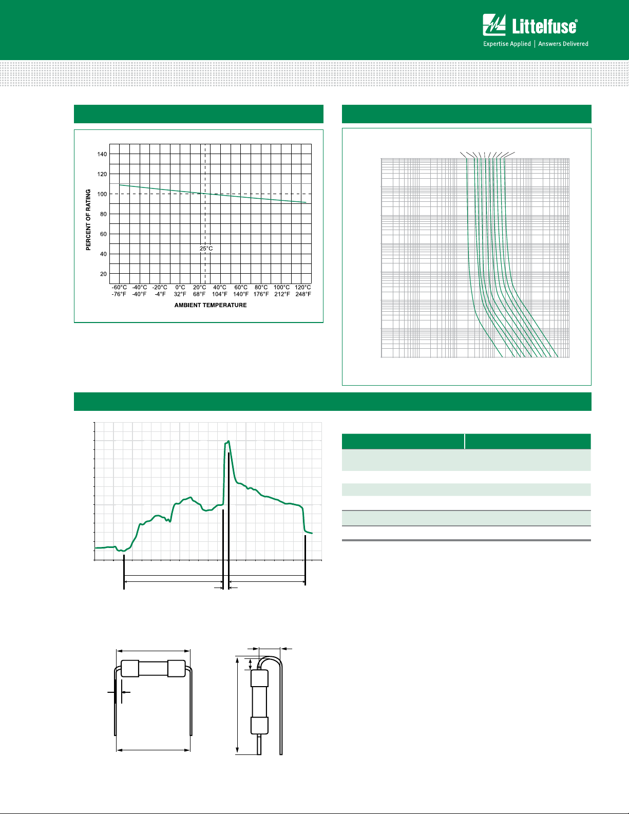
1.6A
1A
2A
2.5A
3.15A
4A
5A
6.3A
8A
10A
A
B
C
C
A
B
5×20 mm > Fast-Acting > 216SP Series
Temperature Rerating Curve
Soldering Parameters - Wave Soldering
Average Time Current Curves
280
260
240
220
200
180
160
140
120
100
80
60
40
20
0
0
102030405060708090
Time (Seconds)
Different values of A and B available, please contact the Littelfuse sales representative in your region:
© 2013 Littelfuse, Inc.
Specifications are subject to change without notice.
Revised: 12/19/13
Preheat Time
Recommended Process Parameters:
Wave Parameter Lead-Free Recommendation
Preheat:
(Depends on Flux Activation Temperature)
Temperature Minimum:
Temperature Maximum:
(Typical Industry Recommendation)
100
° C
150
° C
Preheat Time: 60-180 seconds
Solder Pot Temperature:
280
° C Maximum
Solder Dwell Time: 2-5 seconds
Recommended Hand-Solder Parameters:
100
110
120
130
140
150
160
170
180
190
200
210
220
Dwell Time
230
Cooling Time
Solder Iron Temperature: 350° C +/- 5°C
Heating Time: 5 seconds max.
Note: These devices are not recommended for IR or
Convection Reflow process.
For the pigtailed fuse, please follow the recommendations
below for axial lead forming and mounting into PCB:
Lead forming:
The distance C between cap flat surface and axial lead shall
be greater than 1.0 mm.
PCB mounting:
According to the standard of IPC-A-610, the distance
between PCB and fuse cap is recommended to be a
minimum of 1.5 mm.
Page 3

0216 xxxx M X E SP P
Product Characteristics
Axial Lead & Cartridge Fuses
5×20 mm > Fast-Acting > 216SP Series
Materials
Terminal Strength
Solderability
Product Marking
Dimensions
* 8A and 10A have 0.8mm diameter
All unit in mm.
Body: Ceramic
Cap: Nickel–plated Brass
Leads: Tin–plated Copper
MIL-STD-202G, Method 211A, Test
Condition A
Reference IEC 60127 Second Edition
2003-01 Annex A
Cap 1: Brand logo, current and voltage
ratings
Cap 2: Agency approval marks
20 ± 0.5
5.1 ± 0.6
5.1 ± 0.6
Operating Temperature –55ºC to +125ºC
MIL-STD-202G, Method 107G, Test
Thermal Shock
Condition B (5 cycles, –65ºC to
+125ºC)
Vibration MIL-STD-202G, Method 201A
MIL-STD-202G, Method 103B, Test
Humidity
Condition A (High RH (95%) and
elevated temp (40ºC) for 240 hours)
Salt Spray
MIL-STD-202G, Method 101D, Test
Condition B
Part Numbering System
Series
Current Rating Code
Refer to Amp Code column of
Electrical Characteristics Table
Quantity Code
M = 1000
Packaging Code
X = Filler
Option Codes
Blank : Cartidge Type Fuse
E : Axial Leaded Fuse
Single-Cap Pigtail
Lead-Free
Packaging
Packaging Option Packaging Specification Quantity Packaging Code Reel Size
216SP Series
Bulk N/A 1000 MXE N/A
Additional Information
Datasheet
Resources
Samples
Specifications are subject to change without notice.
© 2013 Littelfuse, Inc.
Revised: 12/19/13
 Loading...