

LITTELFUSE 1.5KE91CA, 1.5KE91C, 1.5KE91A, 1.5KE91, 1.5KE82A Datasheet
...
1
www.littelfuse.com
1.5KE6.8 - 1.5KE440CA series
18
1500 WATT AXIAL TRANSIENT VOLTAGE SUPPRESSORS
Protect sensitive electronics against voltage transients induced by inductive load
switching and lightning. Ideal for the protection of I/O interfaces, Vcc bus, and other
integrated circuits used in telecom, computer, datacom and industrial electronics.
FEATURES
● Breakdown voltage range 6.8 to 440 Volts
● Uni-directional and Bi-directional
● Glass passivated junction
● Low clamping factor
● 100% surge tested
● UL recognised
MAXIMUM RATING
● Peak Pulse Power (Ppk): 1500 Watts (10 x 1000µs)@25°C
(see diagram on page 6 for wave form)
● 5 watt steady state
● Response time: 1 x 10
-12
seconds (theoretical)
● Forward surge rating: 200 Amps, 8.3ms half sine wave,
(uni-directional devices only)
● Operating & storage temperature: -55°C to +150°C
MECHANICAL CHARACTERISTICS
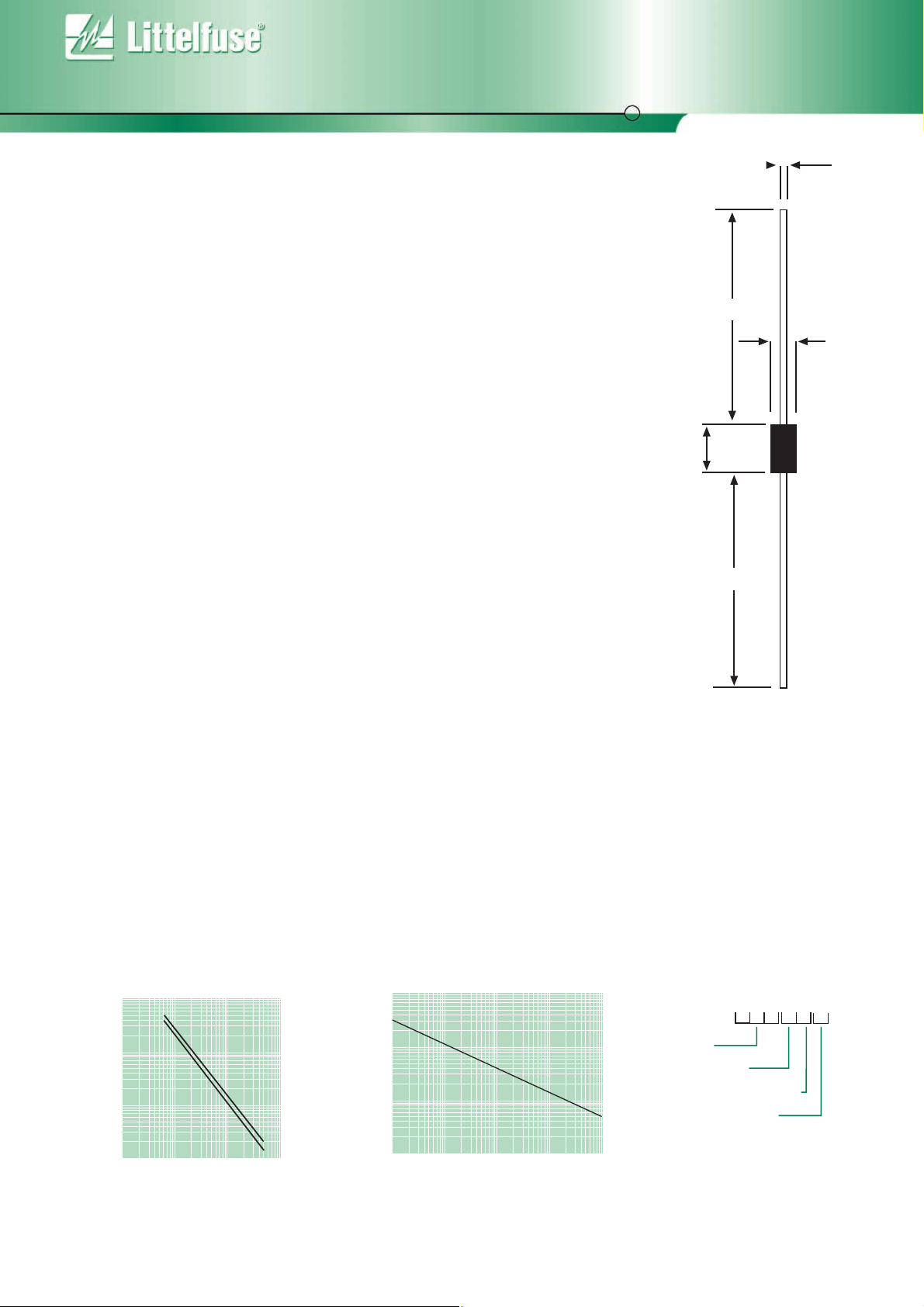
● Case: DO-201AD: Moulded plastic over glass passivated junction
● Terminals: Axial leads, solderable per MIL-STD-202 Method 208
● Solderable leads = 230°C for 10 seconds (1.59mm from case)
● Marking: cathode band, (positive terminal, uni-directional devices only),
device code, logo
● Weight: 1.5 grammes (approx)
Min 25.4
4.826
5.207
Min 25.4
9.155
9.527
0.966 - 1.066
ORDERING INFORMATION
s
Figure 1 - Capacitance vs. Stand-off Voltage Figure 2 - Peak Pulse Power vs. Pulse Time
All dimensions in mm
10000
1000
Cj (pf)
100
● STAND-OFF VOLTAGE
Bi-directional
Uni-directional
Pp
(KW)
100kw
20kw
5kw
2kw
500w
C
1.5KE
Voltage
Bi-Directional
5% Voltage Tolerance
Packaging Option
A
10
1 10 100 1000
Device Stand-off Voltage - Volts
100w
1µs10µs 100µs 1ms 10m
Pulse Time (tp)
B = Bulk (500 pcs)
T = Tape and reeled (1500 pcs)
www.littelfuse.com
19
1.5KE6.8*
1.5KE6.8A*
1.5KE7.5
1.5KE7.5A
1.5KE8.2
1.5KE8.2A
1.5KE9.1
1.5KE9.1A
1.5KE10
1.5KE10A
1.5KE11
1.5KE11A
1.5KE12
1.5KE12A
1.5KE13
1.5KE13A
1.5KE15
1.5KE15A
1.5KE16
1.5KE16A
1.5KE18*
1.5KE18A*
1.5KE20*
1.5KE20A*
1.5KE22
1.5KE22A
1.5KE24*
1.5KE24A*
1.5KE27*
1.5KE27A*
1.5KE30
1.5KE30A
1.5KE33*
1.5KE33A*
1.5KE36
1.5KE36A
1.5KE39*
1.5KE39A*
1.5KE43
1.5KE43A
1.5KE47
1.5KE47A
1.5KE51*
1.5KE51A
Part
Number
(Uni)
Part
Number
(Bi)
1.5KE6.8C*
1.5KE6.8CA*
1.5KE7.5C
1.5KE7.5CA
1.5KE8.2C
1.5KE8.2CA
1.5KE9.1C
1.5KE9.1CA
1.5KE10C
1.5KE10CA
1.5KE11C
1.5KE11CA
1.5KE12C
1.5KE12CA
1.5KE13C
1.5KE13CA
1.5KE15C*
1.5KE15CA*
1.5KE16C
1.5KE16CA
1.5KE18C*
1.5KE18CA*
1.5KE20C
1.5KE20CA
1.5KE22C
1.5KE22CA
1.5KE24C*
1.5KE24CA*
1.5KE27C*
1.5KE27CA*
1.5KE30C
1.5KE30CA
1.5KE33C
1.5KE33CA
1.5KE36C
1.5KE36CA
1.5KE39C
1.5KE39CA
1.5KE43C
1.5KE43CA
1.5KE47C
1.5KE47CA
1.5KE51C
1.5KE51CA
Reverse
Stand off
Voltage
V
R
(Volts)
5.50
5.80
6.05
6.40
6.63
7.02
7.37
7.78
8.10
8.55
8.92
9.40
9.72
10.20
10.50
11.10
12.10
12.80
12.90
13.60
14.50
15.30
16.20
17.10
17.80
18.80
19.40
20.50
21.80
23.10
24.30
25.60
26.80
28.20
29.10
30.80
31.60
33.30
34.80
36.80
38.10
40.20
41.30
43.60
Breakdown
Voltage
V
BR (Volts) @ IT
MIN
6.12
6.45
6.75
7.13
7.38
7.79
8.19
8.60
9.00
9.50
9.90
10.50
10.80
11.40
11.70
12.40
13.50
14.30
14.40
15.20
16.20
17.10
18.00
19.00
19.80
20.90
21.60
22.80
24.30
25.70
27.00
28.50
29.70
31.40
32.40
34.20
35.10
37.10
38.70
40.90
42.30
44.70
45.90
48.50
MAX
7.48
7.14
8.25
7.88
9.02
8.61
10.00
9.55
11.00
10.50
12.10
11.60
13.20
12.60
14.30
13.70
16.50
15.80
17.60
16.80
19.80
18.90
22.00
21.00
24.20
23.10
26.40
25.20
29.70
28.40
33.00
31.50
36.30
34.70
39.60
37.80
42.90
41.00
47.30
45.20
51.70
49.40
56.10
53.60
mA
10.0
10.0
10.0
10.0
10.0
10.0
1.0
1.0
1.0
1.0
1.0
1.0
1.0
1.0
1.0
1.0
1.0
1.0
1.0
1.0
1.0
1.0
1.0
1.0
1.0
1.0
1.0
1.0
1.0
1.0
1.0
1.0
1.0
1.0
1.0
1.0
1.0
1.0
1.0
1.0
1.0
1.0
1.0
1.0
Maximum
Reverse
Leakage
I
R
@ VR
(µA)
1000.0
1000.0
500.0
500.0
200.0
200.0
50.0
50.0
10.0
10.0
5.0
5.0
5.0
5.0
5.0
5.0
5.0
5.0
5.0
5.0
5.0
5.0
5.0
5.0
5.0
5.0
5.0
5.0
5.0
5.0
5.0
5.0
5.0
5.0
5.0
5.0
5.0
5.0
5.0
5.0
5.0
5.0
5.0
5.0
Maximum
Clamping
Voltage
V
C @ I
PP
(Volts)
10.8
10.5
11.7
11.3
12.5
12.1
13.8
13.4
15.0
14.5
16.2
15.6
17.3
16.7
19.0
18.2
22.0
21.2
23.5
22.5
26.5
25.2
29.1
27.7
31.9
30.6
34.7
33.2
39.1
37.5
43.5
41.4
47.7
45.7
52.0
49.9
56.4
53.9
61.9
59.3
67.8
64.8
73.5
70.1
Maximum
Peak Pulse
Current
I
PP
(A)
139.0
143.0
128.0
132.0
120.0
124.0
109.0
112.0
100.0
103.0
93.0
96.0
87.0
90.0
79.0
82.0
68.0
71.0
64.0
67.0
56.5
59.5
51.5
54.0
47.0
49.0
43.0
45.0
38.5
40.0
34.5
36.0
31.5
33.0
29.0
30.0
26.5
28.0
24.0
25.3
22.2
23.2
20.4
21.4
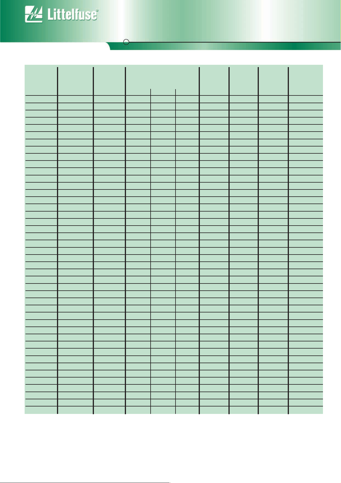
Suffix ‘C’ denotes Bi-directional device. Suffix ‘A’ denotes 5% tolerance device, no suffix denotes a 10% tolerance device.
1. For Bi-directional devices having VR of 10 volts and below, the IR limit is doubled.
2. VF = 3.5 Volts max. for devices of VR <100v, and VF = 5.0 Volts max for devices of VR >100V. IF = 100A, 300 µS square wave.
* Preferred voltages.
Max
Voltage
Temperature
Variation
of V
BR (%/°C)
0.057
0.057
0.061
0.061
0.065
0.065
0.068
0.068
0.073
0.073
0.075
0.075
0.078
0.078
0.081
0.081
0.084
0.084
0.086
0.086
0.088
0.088
0.090
0.090
0.092
0.092
0.094
0.094
0.096
0.096
0.097
0.097
0.098
0.098
0.099
0.099
0.100
0.100
0.101
0.101
0.101
0.101
0.102
0.102
1.5KE6.8 - 1.5KE440CA series
ELECTRICAL SPECIFICATION @ Tamb 25°C
 Loading...