

Page 1

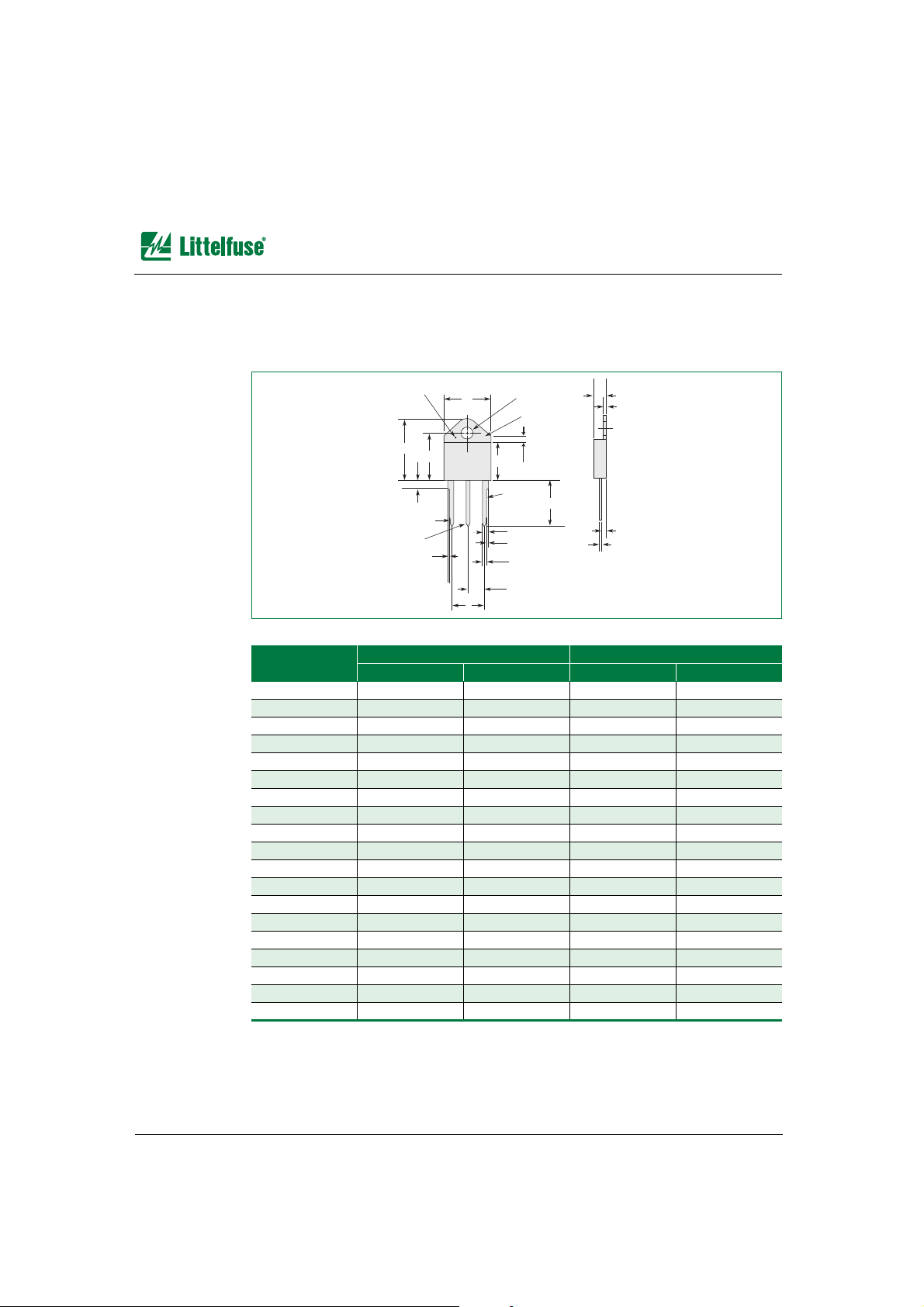
Mechanical Data
9
Telecom Design Guide • © 2006 Littelfuse, Inc. 9 - 1 www.littelfuse.com
/GEJCPKECN&CVC
9
Mechanical Data
The following section describes the mechanical specifications of products in this Telecom
Design Guide.
Gas Plasma Arresters—Package Dimensions / Specifications . . . . . . . . . . . . . . . . . . . . . . . . 9-3
SL1122A Series. . . . . . . . . . . . . . . . . . . . . . . . . . . . . . . . . . . . . . . . . . . . . . . . . . . . . . . . 9-3
SL0902A Series. . . . . . . . . . . . . . . . . . . . . . . . . . . . . . . . . . . . . . . . . . . . . . . . . . . . . . . . 9-3
SL1002A Series. . . . . . . . . . . . . . . . . . . . . . . . . . . . . . . . . . . . . . . . . . . . . . . . . . . . . . . . 9-4
SL1003A Series. . . . . . . . . . . . . . . . . . . . . . . . . . . . . . . . . . . . . . . . . . . . . . . . . . . . . . . . 9-4
SL1011A and SL1011B Series . . . . . . . . . . . . . . . . . . . . . . . . . . . . . . . . . . . . . . . . . . . . 9-5
SL1021A and SL1021B Series . . . . . . . . . . . . . . . . . . . . . . . . . . . . . . . . . . . . . . . . . . . . 9-5
SL1024A and SL1024B Series . . . . . . . . . . . . . . . . . . . . . . . . . . . . . . . . . . . . . . . . . . . . 9-6
SL1411A Series. . . . . . . . . . . . . . . . . . . . . . . . . . . . . . . . . . . . . . . . . . . . . . . . . . . . . . . . 9-7
SIDACtor
®
DO-214AA Package Symbolization . . . . . . . . . . . . . . . . . . . . . . . . . . . . . . . . . . . . 9-8
SIDACtor
®
Devices—Package Dimensions . . . . . . . . . . . . . . . . . . . . . . . . . . . . . . . . . . . . . . . 9-9
DO-214AA . . . . . . . . . . . . . . . . . . . . . . . . . . . . . . . . . . . . . . . . . . . . . . . . . . . . . . . . . . . . 9-9
Modified DO-214AA. . . . . . . . . . . . . . . . . . . . . . . . . . . . . . . . . . . . . . . . . . . . . . . . . . . . 9-10
TO-92. . . . . . . . . . . . . . . . . . . . . . . . . . . . . . . . . . . . . . . . . . . . . . . . . . . . . . . . . . . . . . . 9-11
T10A . . . . . . . . . . . . . . . . . . . . . . . . . . . . . . . . . . . . . . . . . . . . . . . . . . . . . . . . . . . . . . . 9-12
T10B . . . . . . . . . . . . . . . . . . . . . . . . . . . . . . . . . . . . . . . . . . . . . . . . . . . . . . . . . . . . . . . 9-12
T10C . . . . . . . . . . . . . . . . . . . . . . . . . . . . . . . . . . . . . . . . . . . . . . . . . . . . . . . . . . . . . . . 9-13
Modified MS-013 . . . . . . . . . . . . . . . . . . . . . . . . . . . . . . . . . . . . . . . . . . . . . . . . . . . . . . 9-14
Modified TO-220 . . . . . . . . . . . . . . . . . . . . . . . . . . . . . . . . . . . . . . . . . . . . . . . . . . . . . . 9-15
TO-218. . . . . . . . . . . . . . . . . . . . . . . . . . . . . . . . . . . . . . . . . . . . . . . . . . . . . . . . . . . . . . 9-16
R Package—TO-220AB. . . . . . . . . . . . . . . . . . . . . . . . . . . . . . . . . . . . . . . . . . . . . . . . . 9-17
N Package—TO-263 . . . . . . . . . . . . . . . . . . . . . . . . . . . . . . . . . . . . . . . . . . . . . . . . . . . 9-18
SIDACtor
®
Cell . . . . . . . . . . . . . . . . . . . . . . . . . . . . . . . . . . . . . . . . . . . . . . . . . . . . . . . 9-19
TeleLink
®
Surface Mount Fuse—Package Dimensions . . . . . . . . . . . . . . . . . . . . . . . . . . . . . 9-20
Electronic Fuses—Package Dimensions . . . . . . . . . . . . . . . . . . . . . . . . . . . . . . . . . . . . . . . . 9-21
2AG Slo-Blo
®
Fuse—229P / 230P Series . . . . . . . . . . . . . . . . . . . . . . . . . . . . . . . . . . . 9-21
NANO
2®
Fuse—451 / 453 Series . . . . . . . . . . . . . . . . . . . . . . . . . . . . . . . . . . . . . . . . . 9-21
NANO
2®
Fuse—452 / 454 Series . . . . . . . . . . . . . . . . . . . . . . . . . . . . . . . . . . . . . . . . . 9-22
SMF OMNI-BLOK
®
Fuse Block—154 Series . . . . . . . . . . . . . . . . . . . . . . . . . . . . . . . . 9-22
NANO
2®
250 V UMF Fuse—464 / 465 Series. . . . . . . . . . . . . . . . . . . . . . . . . . . . . . . . 9-23
481 Series Alarm Indicating Fuse . . . . . . . . . . . . . . . . . . . . . . . . . . . . . . . . . . . . . . . . . 9-23
482 Series Alarm Indicating Fuseholder . . . . . . . . . . . . . . . . . . . . . . . . . . . . . . . . . . . . 9-24
DC Power Fuses—Package Dimensions. . . . . . . . . . . . . . . . . . . . . . . . . . . . . . . . . . . . . . . . 9-25
L17T Series . . . . . . . . . . . . . . . . . . . . . . . . . . . . . . . . . . . . . . . . . . . . . . . . . . . . . . . . . . 9-25
TLN Series. . . . . . . . . . . . . . . . . . . . . . . . . . . . . . . . . . . . . . . . . . . . . . . . . . . . . . . . . . . 9-26
TLS Series . . . . . . . . . . . . . . . . . . . . . . . . . . . . . . . . . . . . . . . . . . . . . . . . . . . . . . . . . . . 9-27
LTFD Series. . . . . . . . . . . . . . . . . . . . . . . . . . . . . . . . . . . . . . . . . . . . . . . . . . . . . . . . . . 9-28
LTFD 101 Series . . . . . . . . . . . . . . . . . . . . . . . . . . . . . . . . . . . . . . . . . . . . . . . . . . . . . . 9-30
Page 2

www.littelfuse.com 9 - 2 © 2006 Littelfuse, Inc. • Telecom Design Guide
Summary of Packing Options . . . . . . . . . . . . . . . . . . . . . . . . . . . . . . . . . . . . . . . . . . . . . . . . .9-31
Packing Options . . . . . . . . . . . . . . . . . . . . . . . . . . . . . . . . . . . . . . . . . . . . . . . . . . . . . . . . . . . 9-36
SL1122A Series . . . . . . . . . . . . . . . . . . . . . . . . . . . . . . . . . . . . . . . . . . . . . . . . . . . . . . .9-36
SL0902A Series . . . . . . . . . . . . . . . . . . . . . . . . . . . . . . . . . . . . . . . . . . . . . . . . . . . . . . .9-36
SL1002A Series . . . . . . . . . . . . . . . . . . . . . . . . . . . . . . . . . . . . . . . . . . . . . . . . . . . . . . .9-37
SL1003A Series . . . . . . . . . . . . . . . . . . . . . . . . . . . . . . . . . . . . . . . . . . . . . . . . . . . . . . .9-37
SL1011A/B Series . . . . . . . . . . . . . . . . . . . . . . . . . . . . . . . . . . . . . . . . . . . . . . . . . . . . . 9-38
SL1021A/B Series . . . . . . . . . . . . . . . . . . . . . . . . . . . . . . . . . . . . . . . . . . . . . . . . . . . . .9-38
SL1024A/B Series . . . . . . . . . . . . . . . . . . . . . . . . . . . . . . . . . . . . . . . . . . . . . . . . . . . . .9-38
SL1411A Series . . . . . . . . . . . . . . . . . . . . . . . . . . . . . . . . . . . . . . . . . . . . . . . . . . . . . . .9-38
DO-214AA . . . . . . . . . . . . . . . . . . . . . . . . . . . . . . . . . . . . . . . . . . . . . . . . . . . . . . . . . . .9-39
TO-92 . . . . . . . . . . . . . . . . . . . . . . . . . . . . . . . . . . . . . . . . . . . . . . . . . . . . . . . . . . . . . . .9-40
T10A. . . . . . . . . . . . . . . . . . . . . . . . . . . . . . . . . . . . . . . . . . . . . . . . . . . . . . . . . . . . . . . .9-41
T10B. . . . . . . . . . . . . . . . . . . . . . . . . . . . . . . . . . . . . . . . . . . . . . . . . . . . . . . . . . . . . . . .9-42
T10C. . . . . . . . . . . . . . . . . . . . . . . . . . . . . . . . . . . . . . . . . . . . . . . . . . . . . . . . . . . . . . . . 9-43
Modified MS-013 Six-pin . . . . . . . . . . . . . . . . . . . . . . . . . . . . . . . . . . . . . . . . . . . . . . . .9-44
Modified TO-220. . . . . . . . . . . . . . . . . . . . . . . . . . . . . . . . . . . . . . . . . . . . . . . . . . . . . . .9-45
TO-263 . . . . . . . . . . . . . . . . . . . . . . . . . . . . . . . . . . . . . . . . . . . . . . . . . . . . . . . . . . . . . .9-46
TeleLink
®
Surface Mount Fuse. . . . . . . . . . . . . . . . . . . . . . . . . . . . . . . . . . . . . . . . . . . . 9-47
229P / 230P Series . . . . . . . . . . . . . . . . . . . . . . . . . . . . . . . . . . . . . . . . . . . . . . . . . . . .9-50
Lead Form Options . . . . . . . . . . . . . . . . . . . . . . . . . . . . . . . . . . . . . . . . . . . . . . . . . . . . . . . . .9-51
Modified TO-220 Type 60 . . . . . . . . . . . . . . . . . . . . . . . . . . . . . . . . . . . . . . . . . . . . . . . . 9-51
Modified TO-220 Type 61 . . . . . . . . . . . . . . . . . . . . . . . . . . . . . . . . . . . . . . . . . . . . . . . . 9-52
Modified TO-220 Type 62 . . . . . . . . . . . . . . . . . . . . . . . . . . . . . . . . . . . . . . . . . . . . . . . . 9-52
Page 3
*DV3ODVPD$UUHVWHUV³3DFNDJH'LPHQVLRQV6SHFLILFDWLRQV
Telecom Design Guide • © 2006 Littelfuse, Inc. 9 - 3 www.littelfuse.com
/GEJCPKECN&CVC
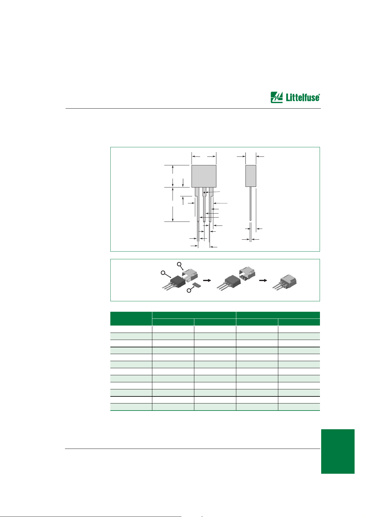
*DV3ODVPD$UUHVWHUV³3DFNDJH'LPHQVLRQV6SHFLILFDWLRQV
The following illustrations show package dimensions and mechanical specifications for
each of the gas plasma arresters.
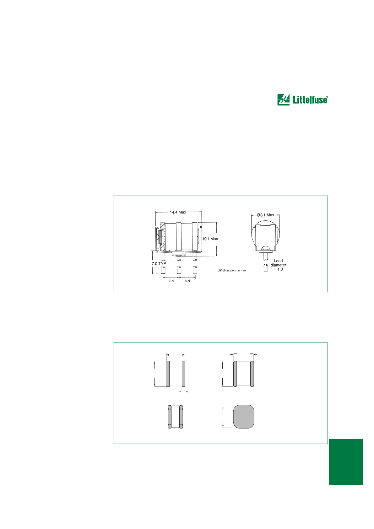
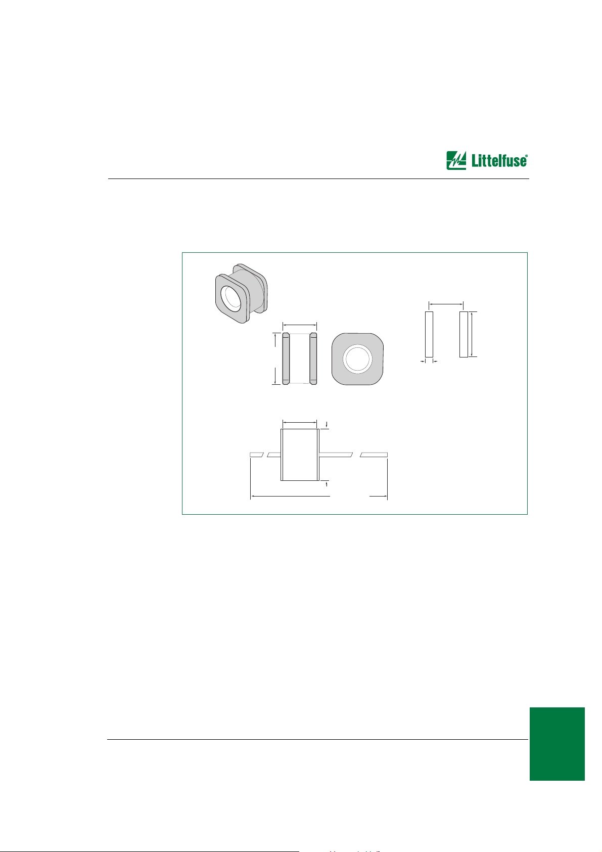
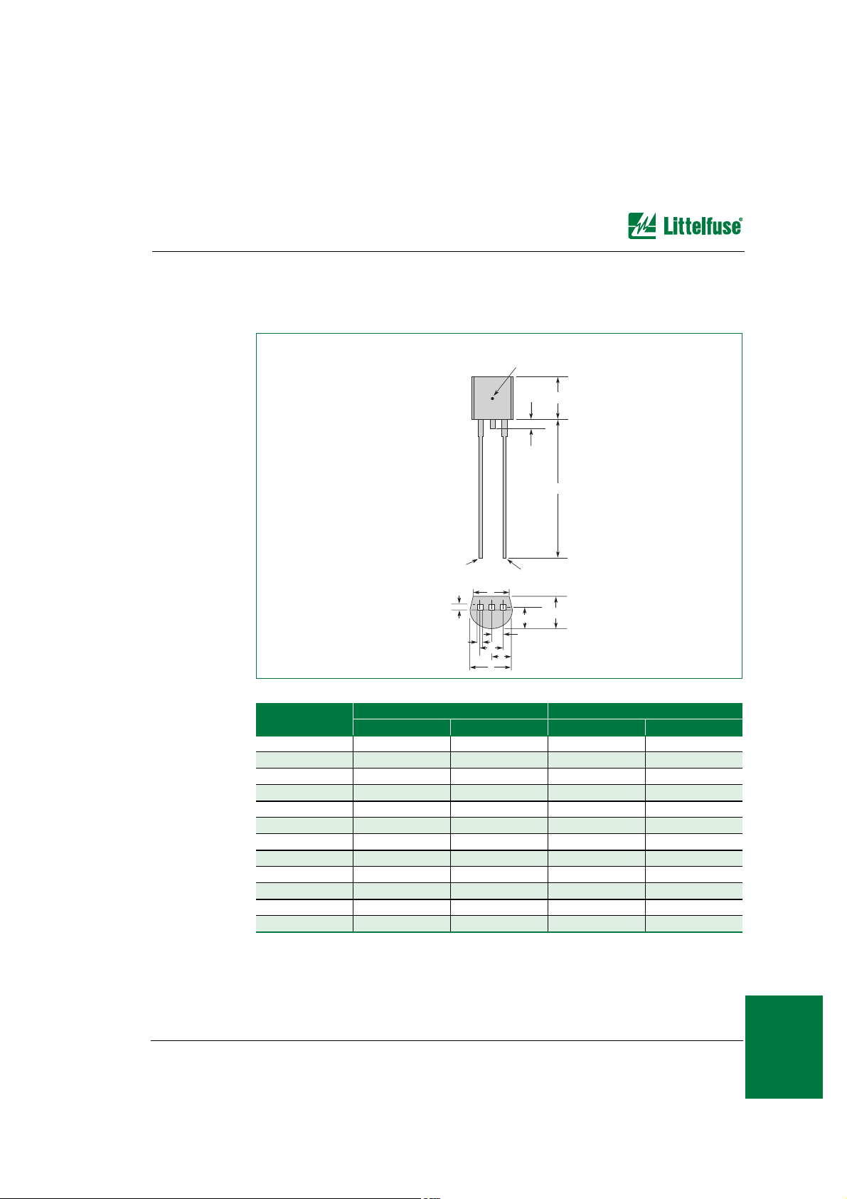
SL1122A Series
The SL1122A series device weighs 2.7 grams (0.095 ounces). Body material is ceramic.
The electrode base is made of nickel iron alloy, and the electrode plating material is
bright Sn. Each device is marked with an LF logo, voltage, and date code.
SL0902A Series
The SL0902A series device weighs 0.33 grams (0.011 ounces). Body material is ceramic.
The electrode base is made of copper alloy, and the electrode plating material is bright Sn.
Each device is marked with an LF logo, voltage, and date code.
0.196 ±0.007
(5.0 ±0.2)
Recommended Pad Layout
Dimensions are in inches
(and millimeters).
0.196 ±0.007
(5.0 ±0.2)
0.196 ±0.007
(5.0 ±0.2)
SL0902AxxxSM
GDT Seating Plane
for SL0902AxxxSM
0.180
(4.50)
0.204
(5.10)
0.0279
(0.70)
Page 4
www.littelfuse.com 9 - 4 © 2006 Littelfuse, Inc. • Telecom Design Guide
*DV3ODVPD$UUHVWHUV³3DFNDJH'LPHQVLRQV6SHFLILFDWLRQV
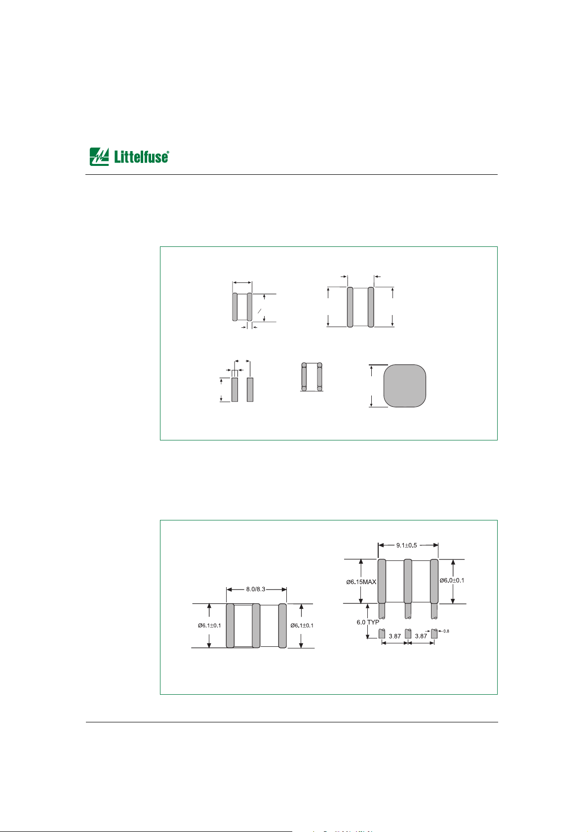
SL1002A Series
The SL1002A series device weighs 0.63 grams (0.022 ounces). Body material is ceramic.
The electrode base is made of nickel iron alloy, and the electrode plating material is
bright Sn. Each device is marked with an LF logo, voltage, and date code.
SL1003A Series
The SL1003A series device weighs 1.5 grams (0.083 ounces). Body material is ceramic.
The electrode base is made of nickel iron alloy, and the electrode plating material is
bright Sn. Each device is marked with an LF logo, voltage, and date code.
0.165 ±0.007
(4.2 ±0.2)
Dimensions are in inches
(and millimeters).
SL1002AxxxC
0.236 ±0.007
(O6.0 ±0.2)
0.031 (0.8)
SL1002AxxxSM
0.244 ±0.004
(6.2 ±0.1)
0.169 ±0.019
(4.3 ±0.3)
0.240 ±0.004
(6.1 ±0.1)
SL1002AxxxSM
Recommended
Pad Size
GDT Showing
Seating Plane
for SL1002AxxxSM
0.244 ±0.004
(6.2 ±0.1)
0.138 (3.5)
0.051 (1.3)
0.197 (5.0)
SL1003AxxxC SL1003AxxxR
Dimensions are in millimeters.
Page 5
*DV3ODVPD$UUHVWHUV³3DFNDJH'LPHQVLRQV6SHFLILFDWLRQV
Telecom Design Guide • © 2006 Littelfuse, Inc. 9 - 5 www.littelfuse.com
/GEJCPKECN&CVC
SL1011A and SL1011BSeries
The SL1011A series device and the SL1011B series device weigh 2.7 grams (0.095
ounces). Body material is ceramic. The electrode base is made of nickel iron alloy, and the
electrode plating material is bright Sn. Each device is marked with an LF logo, voltage, and
date code.
SL1021A and SL1021BSeries
The SL1021A series device weighs 2.7 grams (0.095 ounces). The SL1021B series device
weighs 0.63 grams (0.022 ounces). Body material is ceramic. The electrode base is made
of nickel iron alloy, and the electrode plating material is bright Sn. Each device is marked
with an LF logo, voltage, and date code. The SL1021B series markings are in blue.
0.236 ±0.007
(6.0 ±0.2)
2.362 ±0.016
(60 ±0.4)
0.236 ±0.007
(6.0 ±0.2)
0.315 ±0.007
(8.0 ±0.2)
Dimensions are in inches
(and millimeters).
SL1011AxxxA SL1011AxxxC
MIN
Dimensions are in millimeters
and tolerance is ±0.2 mm
(unless otherwise specified).
SL1021AxxxC
SL1021BxxxC
SL1021AxxxR
SL1021BxxxR
SL1021AxxxZ
SL1021BxxxZ
SL1021AxxxP
SL1021BxxxP
SL1021AxxxS
SL1021BxxxS
SL1021AxxxY
SL1021BxxxY
With Failsafe
SL1021AxxxRF
SL1021BxxxRF
1.37
1.37
10.7 ±0.2
1.37
8.0 ±0.15
∅
8.0 ±0.15
6.4 ±0.15
6.4 ±0.15
4.0
8.4 MAX
11.8
4.5
7.5
10.2
4.4 ±0.15
4.4 ±0.15
6.0 ±0.15
6.0 ±0.15
7.5
4.0
5.5 ±0.15
5.5 ±0.15
7.5
4.5
4.75 ±0.15
4.75 ±0.15
1.3
7.5
4.5
4.4 ±0.15
4.4 ±0.15
1.3
7.5
Page 6
www.littelfuse.com 9 - 6 © 2006 Littelfuse, Inc. • Telecom Design Guide
*DV3ODVPD$UUHVWHUV³3DFNDJH'LPHQVLRQV6SHFLILFDWLRQV
SL1024A and SL1024BSeries
The SL1024A series device and the SL1024B series device weigh 2.7 grams (0.095
ounces). Body material is ceramic. The electrode base is made of nickel iron alloy, and the
electrode plating material is bright Sn. Each device is marked with an LF logo, voltage, and
date code in red.
0.41 ±0.019
(10.5 ±0.5)
Dimensions are in inches
(and millimeters).
0.315 ±0.01
(8 ±0.3)
Standard Core (C)
0.41 ±0.019
(10.5 ±0.5)
0.315 ±0.01
(8 ±0.3)
4.4 Leg Pitch (R)
ø 0.039 (1.0)
0.173
(4.4)
0.173
(4.4)
0.276
(7.0) TYP
0.41 ±0.019
(10.5 ±0.5)
0.315 ±0.01
(8 ±0.3)
With Wrap Failsafe (RF/RS)
ø 0.039 (1.0)
0.173
(4.4)
0.173
(4.4)
0.374 MAX
(9.5 MAX)
0.315 ±0.008
(8 ±0.2)
ø 0.039 ±0.008
(1.0 ±0.2)
0.276
(7.0) TY
P
Page 7
*DV3ODVPD$UUHVWHUV³3DFNDJH'LPHQVLRQV6SHFLILFDWLRQV
Telecom Design Guide • © 2006 Littelfuse, Inc. 9 - 7 www.littelfuse.com
/GEJCPKECN&CVC
SL1411A Series
The SL1411A series device weighs 2.7 grams (0.095 ounces). Body material is ceramic.
The electrode base is made of nickel iron alloy, and the electrode plating material is bright
Sn. Each device is marked with an LF logo, voltage, and date code.
0.315 ±0.012
(8.0 ±0.2)
0.236 ±0.012
(6.0 ±0.3)
Pad Outline
Dimensions are in inches
(and millimeters).
Recommended pad layout for SM
0.276
(7.0)
0.213
(5.4)
0.051
(1.3)
0.315 ±0.012
(8.0 ±0.2)
0.236 ±0.008
(6.0 ±0.2)
2.36 ±0.016
(60.0 ±0.4)
Page 8
www.littelfuse.com 9 - 8 © 2006 Littelfuse, Inc. • Telecom Design Guide
6,'$&WRU'2$$3DFNDJH6\PEROL]DWLRQ
6,'$&WRU'2$$3DFNDJH6\PEROL]DWLRQ
Note: Date code is located below the symbolized part number.
Part Number Part Number Part Number
Catalog Symbolized Catalog Symbolized Catalog Symbolized
P0080SAL P-8A P1101SCL P01C P2600SAL P26A
P0080SAMCL P-8AM P1200SAL P12A P2600SBL P26B
P0080SBL P-8B P1200SBL P12B P2600SCL P26C
P0080SCL P-8C P1200SCL P12C P2600SDL P26D
P0080SDL P-8D P1200SDL P12D P2600SCMCL P26CM
P0080SCMCL P-8CM P1200SCMCL P12CM P2602SAL P262A
P0300SAL P03A P1300SAL P13A P2702CAL P27A
P0300SAMCL P03AM P1300SBL P13B P3002CAL P30A
P0300SBL P03B P1300SCL P13C P3002CBL P30B
P0300SCL P03C P1300SDL P13D P3002SAL P30A
P0300SCMCL P03CM P1300SCMCL P13CM P3002SBL P30B
P0640SAL P06A P1302SAL P132A P3100SAL P31A
P0640SBL P06B P1402CAL P14A P3100SBL P31B
P0640SCL P06C P1500SAL P15A P3100SCL P31C
P0640SDL P06D P1500SBL P15B P3100SDL P31D
P0640SCMCL P06CM P1500SCL P15C P3100SCMCL P31CM
P0641CA2L P62A P1500SDL P15D P3500SAL P35A
P0641SAL P61A P1500SCMCL P15CM P3500SBL P35B
P0641SCL P61C P1502SAL P152A P3500SCL P35C
P0720SAL P07A P1602CAL P16A P3500SDL P35D
P0720SBL P07B P1800SAL P18A P3500SCMCL P35CM
P0720SCL P07C P1800SBL P18B P3502SAL P352A
P0720SDL P07D P1800SCL P18C P3602CAL P36A
P0720SCMCL P07CM P1800SDL P18D P4202CAL P42A
P0721CA2L P72A P1800SCMCL P18CM P4202SAL P422A
P0721SAL P71A P1802SAL P182A P4802CAL P48A
P0721SCL P71C P2000SAL P20A P4802SAL P482A
P0900SAL P09A P2000SBL P20B P6002CAL P60A
P0900SBL P09B P2000SCL P20C P6002CBL P60B
P0900SCL P09C P2000SCMCL P20CM P6002SAL P602A
P0900SDL P09D P2202CAL P22A B1100CAL B10A
P0900SCMCL P09CM P2300SAL P23A B1100CCL B10C
P0901CA2L P92A P2300SBL P23B B1160CAL B16A
P0901SAL P91A P2300SCL P23C B1160CCL B16C
P0901SCL P91C P2300SDL P23D B1200CAL B12A
P1100SAL P11A P2300SCMCL P23CM B1200CCL B12C
P1100SBL P11B P2302SAL P232A B2050CAL B25A
P1100SCL P11C P2500SAL P25A B2050CCL B25C
P1100SDL P11D P2500SBL P25B
P1100SCMCL P11CM P2500SCL P25C
P1101CA2L P02A P2500SDL P25D
P1101SAL P01A P2500SCMCL P25CM
Page 9
6,'$&WRU'HYLFHV³3DFNDJH'LPHQVLRQV
Telecom Design Guide • © 2006 Littelfuse, Inc. 9 - 9 www.littelfuse.com
/GEJCPKECN&CVC
6,'$&WRU'HYLFHV³3DFNDJH'LPHQVLRQV
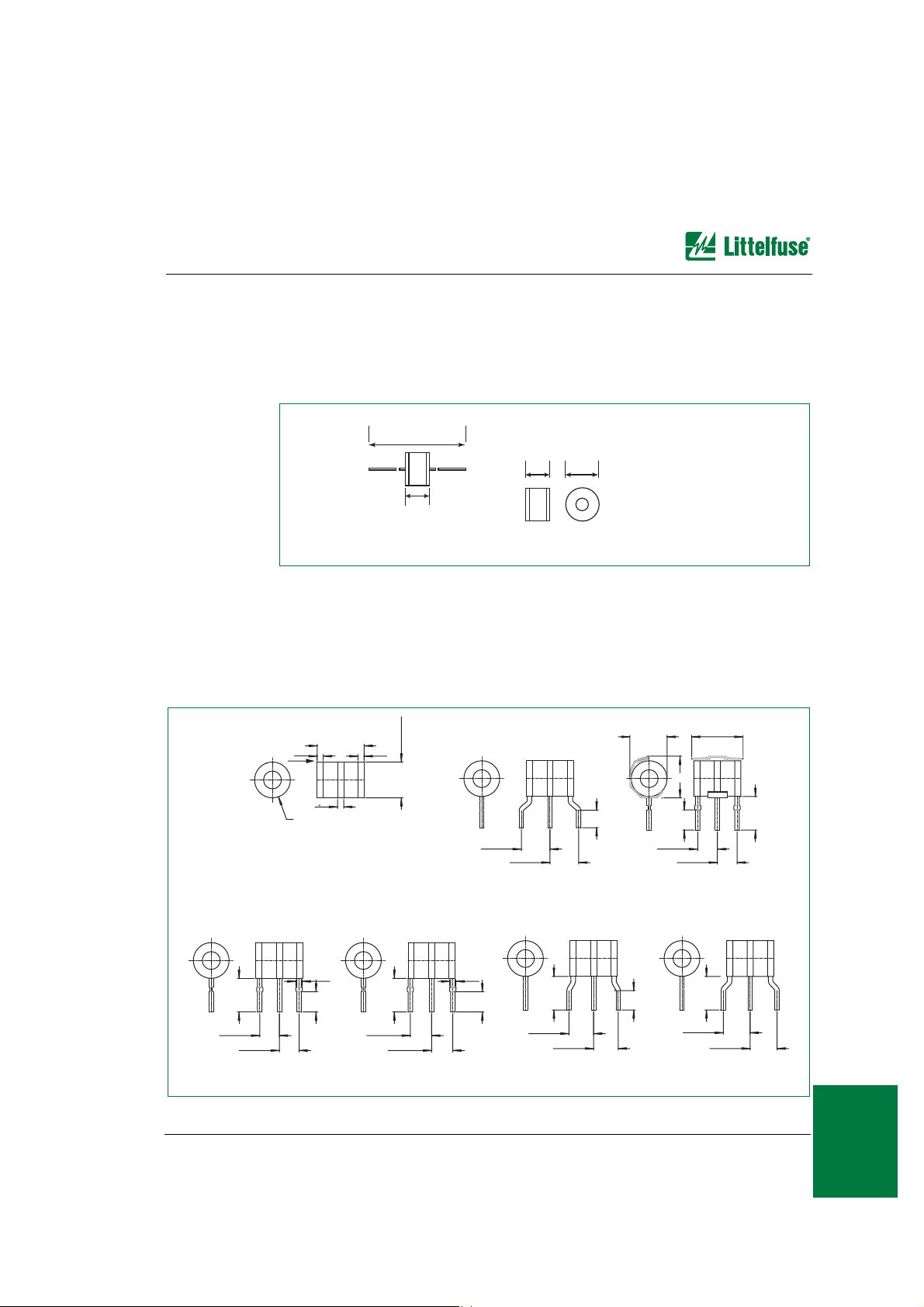
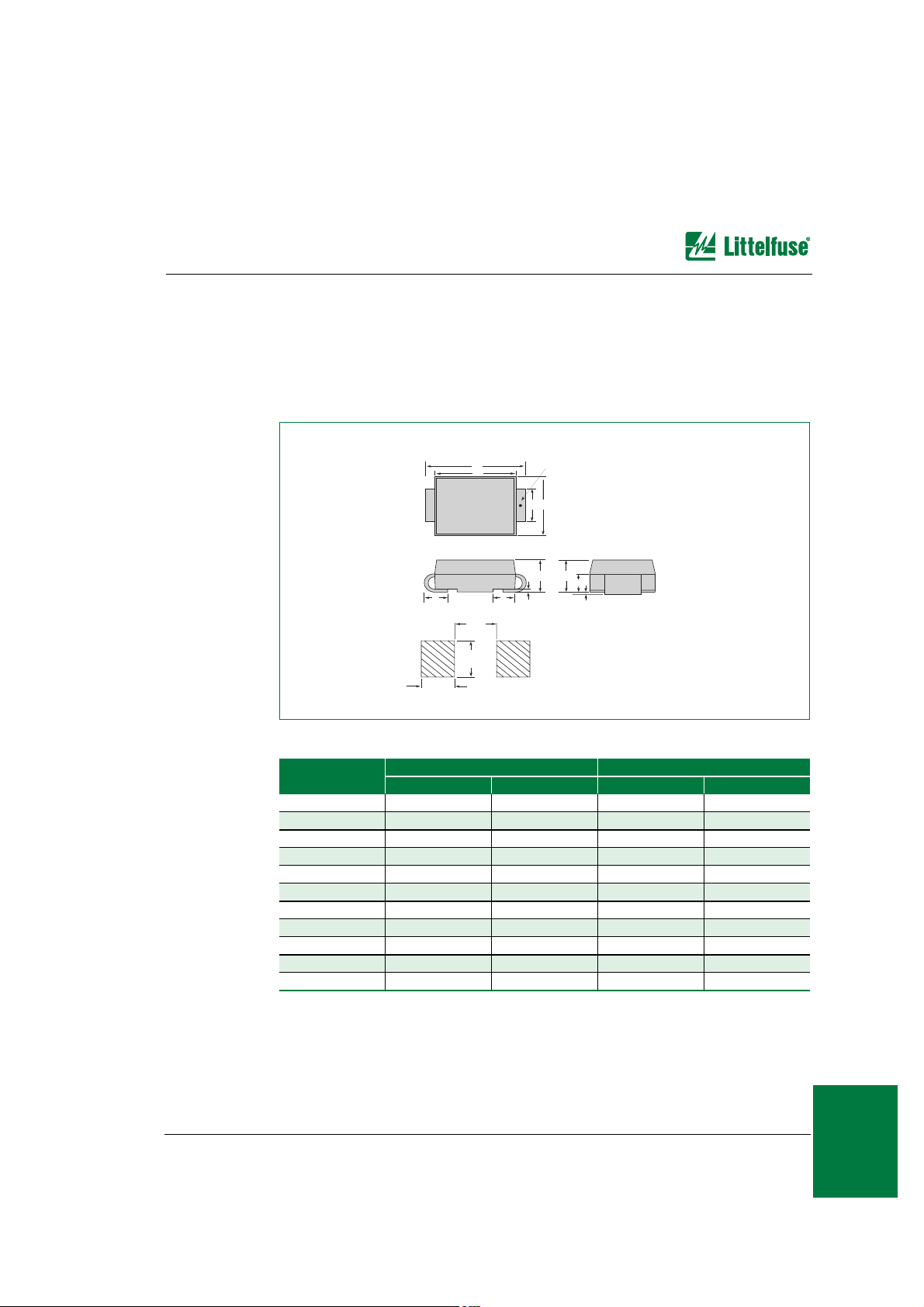
DO-214AA
The DO-214AA package is designed to meet mechanical standards as set forth in JEDEC
publication number 95, except for F and G dimensions.
Note: A stripe is marked on some parts, to indicate the cathode. IPC-SM-782 recommends 2.4 instead of 2.0.
Notes:
• Dimensions and tolerances per ASME Y14.5M-1994
• Mold flash shall not exceed 0.13 mm per side.
• Dimensions B and C apply to plated leads.
• All leads are insulated from case. Case is electrically non-conductive. (Rated at 1600 V ac rms for one
minute from leads to case over the operating temperature range)
• Dimension C is measured on the flat section of the lead.
Dimension
Inches Millimeters
MIN MAX MIN MAX
A 0.140 0.155 3.56 3.94
B 0.205 0.220 5.21 5.59
C 0.077 0.083 1.96 2.11
D 0.166 0.180 4.22 4.57
E 0.036 0.063 0.91 1.60
F 0.066 0.083 1.67 2.11
G 0.004 0.008 0.10 0.20
H 0.077 0.086 1.95 2.18
J 0.043 0.053 1.09 1.35
K 0.008 0.012 0.20 0.30
L 0.027 0.049 0.69 1.24
0.079
(2.0)
0.110
(2.8)
0.079
(2.0)
Pad Outline
(MM)
H
K
JE
F
L
G
A
C
B
D
Case
Temperature
Measurement
Point
Dimensions are in inches
(and millimeters).
Page 10
www.littelfuse.com 9 - 10 © 2006 Littelfuse, Inc. • Telecom Design Guide
6,'$&WRU'HYLFHV³3DFNDJH'LPHQVLRQV
Modified DO-214AA
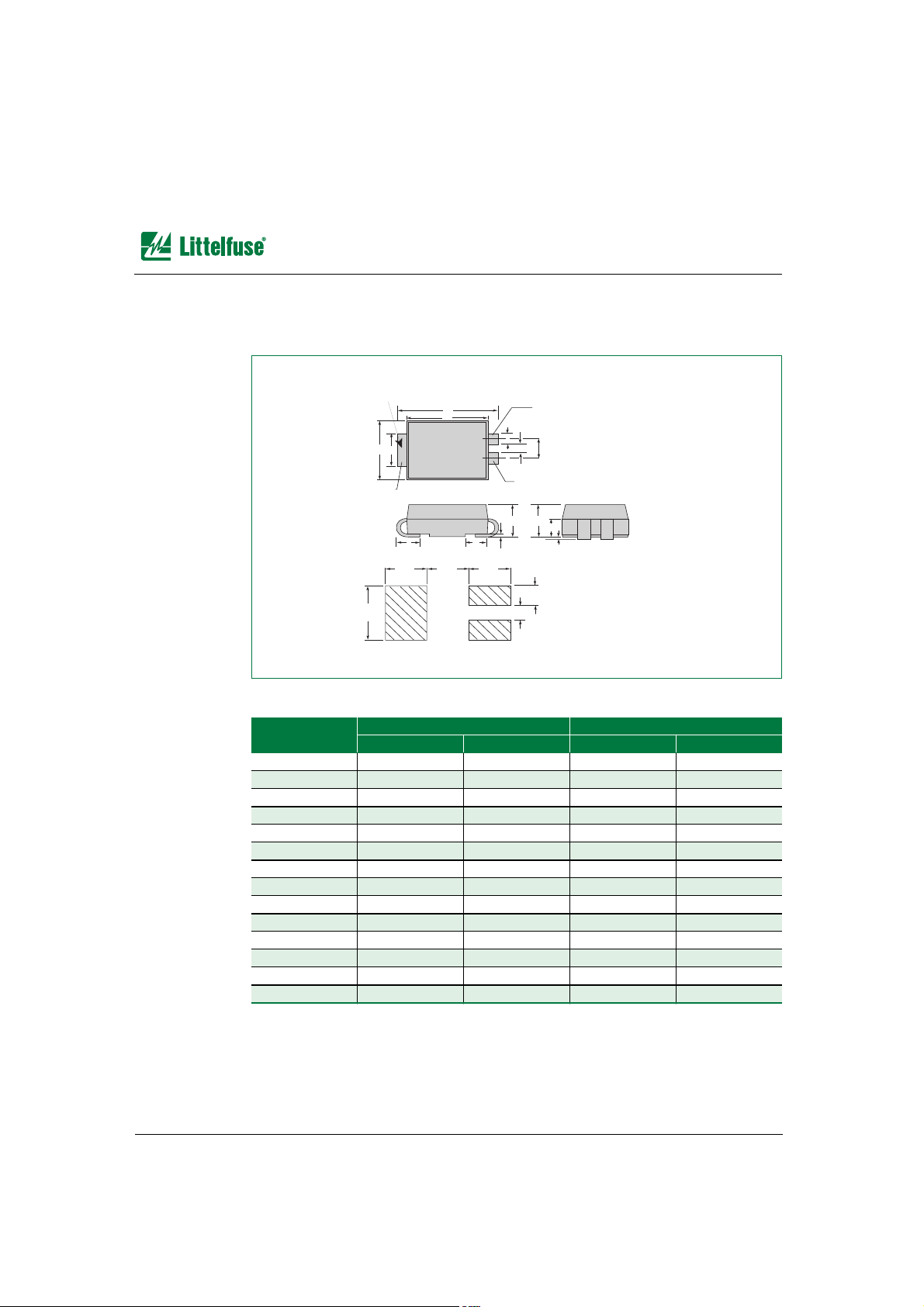
The Modified DO-214AA package is a three-leaded surface mount (SM) package.
Note: A stripe is marked on some parts, to indicate the cathode. IPC-SM-782 recommends 2.4 instead of 2.0.
Notes:
• Dimensions and tolerancing per ASME Y14.5M-1994
• Mold flash shall not exceed 0.13 mm per side.
• Dimensions B and C apply to plated leads.
• All leads are insulated from case. Case is electrically non-conductive. (Rated at 1600 V ac rms for one
minute from leads to case over the operating temperature range)
Dimension
Inches Millimeters
MIN MAX MIN MAX
A 0.140 0.155 3.56 3.94
B 0.205 0.220 5.21 5.59
C 0.077 0.083 1.96 2.11
D 0.166 0.180 4.22 4.57
E 0.036 0.063 0.91 1.60
F 0.066 0.083 1.67 2.11
G 0.004 0.008 0.10 0.20
H 0.077 0.086 1.95 2.18
J 0.043 0.053 1.09 1.35
K 0.008 0.012 0.20 0.30
L 0.027 0.049 0.69 1.24
M 0.022 0.028 0.56 0.71
N 0.027 0.033 0.69 0.84
P 0.052 0.058 1.32 1.47
0.079
(2.0)
0.040
(1.0)
0.030
(0.76)
0.079
(2.0)
0.079
(2.0)
0.110
(2.8)
Pad Outline
(MM)
H
K
JE
F
L
G
A
C
B
M
D
Temperature
Measurement
Point
N
P
PIN 3
PIN 1
PIN 2
Dimensions are in inches
(and millimeters).
Page 11
6,'$&WRU'HYLFHV³3DFNDJH'LPHQVLRQV
Telecom Design Guide • © 2006 Littelfuse, Inc. 9 - 11 www.littelfuse.com
/GEJCPKECN&CVC
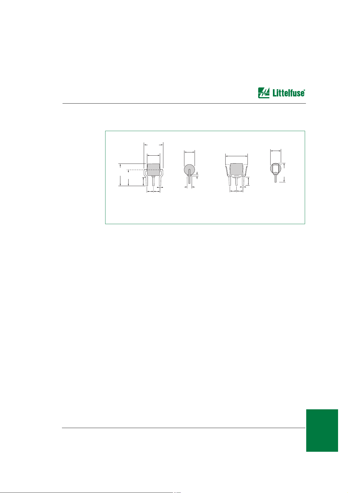
TO-92
The TO-92 is designed to meet mechanical standards as set forth in JEDEC publication
number 95.
Notes:
• Type 70 lead form as shown is standard for the E package.
• All leads are insulated from case. Case is electrically non-conductive. (Rated at 1600 V ac rms for one
minute from leads to case over the operating temperature range)
• Mold flash shall not exceed 0.13 mm per side.
Dimension
Inches Millimeters
MIN MAX MIN MAX
A 0.176 0.196 4.47 4.98
B 0.500 12.70
D 0.095 0.105 2.41 2.67
E 0.150 3.81
F 0.046 0.054 1.16 1.37
G 0.135 0.145 3.43 3.68
H 0.088 0.096 2.23 2.44
J 0.176 0.186 4.47 4.73
K 0.088 0.096 2.23 2.44
L 0.013 0.019 0.33 0.48
M 0.013 0.017 0.33 0.43
N 0.060 1.52
A
B
Temperature
Measurement Point
MT2/PIN 3
MT1/PIN 1
E
H
G
F
D
K
J
L
M
N
Page 12
www.littelfuse.com 9 - 12 © 2006 Littelfuse, Inc. • Telecom Design Guide
6,'$&WRU'HYLFHV³3DFNDJH'LPHQVLRQV
T10A
The T10A device is designed to meet mechanical standards as set forth in JEDEC
publication number 95.
T10B
The T10B device is designed to meet mechanical standards as set forth in JEDEC
publication number 95.
25.4 MIN
3.05
3.25
0.76
0.86
25.4 MIN
6.10
6.47
Dimensions are in millimeters.
25.4 MIN
25.4 MIN
Dimensions are in millimeters.
0.0 - 1.066
4.826
5.207
9.146
9.527
Page 13
6,'$&WRU'HYLFHV³3DFNDJH'LPHQVLRQV
Telecom Design Guide • © 2006 Littelfuse, Inc. 9 - 13 www.littelfuse.com
/GEJCPKECN&CVC
T10C
The T10C device design is not referenced to any JEDEC standard.
0.173
(4.4)
0.173
(4.4)
0.623
(15.83)
0.037
(0.94)
0.437
(11.12)
0.465
(11.81)
0.458
(11.63)
0.417
(10.60)
0.130
(3.30)
0.039
(0.99)
0.328
(8.33)
0.173
(4.4)
0.173
(4.4)
0.177 (4.5)
MIN
0.610 +0.020
(15.5 +0.5)
With Failsafe
0.333 (8.45)
MAX
0.333 (8.45)
MAX
Dimensions are in inches
(and millimeters).
Page 14
www.littelfuse.com 9 - 14 © 2006 Littelfuse, Inc. • Telecom Design Guide
6,'$&WRU'HYLFHV³3DFNDJH'LPHQVLRQV
Modified MS-013
The Modified MS-013 is designed to meet mechanical standards as set forth in JEDEC
publication number 95.
Notes:
• Dimensions and tolerances per ASME Y14.5M-1982
• Mold flash shall not exceed 0.13 mm per side.
• All leads are insulated from case. Case is electrically non-conductive. (Rated at 1600 V ac rms for one
minute from leads to case over the operating temperature range)
• D dimension tolerance is ± 0.005 in (0.127 mm).
Dimension
Inches Millimeters
MIN MAX MIN MAX
A 0.360 0.364 9.14 9.25
B 0.352 0.356 8.94 9.04
C 0.400 0.412 10.16 10.46
D 0.043 0.043 1.09 1.09
E 0.047 0.055 1.19 1.40
F 0.293 0.297 7.44 7.54
G 0.289 0.293 7.34 7.44
H 0.089 0.093 2.26 2.36
J 0.041 0.049 1.04 1.24
K 0.020 0.51
BSC 0.133 0.143 3.38 3.63
C
G
7
˚
TYP
Mold Split Line
A
B
BSC
7
˚
TYP
A
D
E
7
˚
TYP
7
˚
TYP
F
H
J
Burr Side
4
˚
MIN Length
of Flat
Detail A
0.065
(1.65)
K
96
˚
0.460
(11.68)
0.138
(3.50)
0.059
(1.50)
Pad Outline
A
Dimensions are in inches
(and millimeters).
Page 15
6,'$&WRU'HYLFHV³3DFNDJH'LPHQVLRQV
Telecom Design Guide • © 2006 Littelfuse, Inc. 9 - 15 www.littelfuse.com
/GEJCPKECN&CVC
Modified TO-220
The Modified TO-220 package is designed to meet mechanical standards as set forth in
JEDEC publication number 95.
Notes:
• All leads are insulated from case. Case is electrically non-conductive. (Rated at 1600 V ac rms for one
minute from leads to case over the operating temperature range)
• Mold flash shall not exceed 0.13 mm per side.
Dimension
Inches Millimeters
MIN MAX MIN MAX
A 0.400 0.410 10.16 10.42
D 0.360 0.375 9.14 9.53
F 0.110 0.130 2.80 3.30
G 0.540 0.575 13.71 14.61
H 0.025 0.035 0.63 0.89
J 0.195 0.205 4.95 5.21
K 0.095 0.105 2.41 2.67
L 0.075 0.085 1.90 2.16
M 0.070 0.085 1.78 2.16
N 0.018 0.024 0.46 0.61
O 0.178 0.188 4.52 4.78
P 0.290 0.310 7.37 7.87
D
F
P
G
A O
Temperature
Measurement
Point
PIN 3
PIN 2
PIN 1
J
H
L
K
M
N
3
2
1
1 A-Pack
2 A-Pack Failsafe Clip
3 A-Pack Failsafe Solder Preform
With Failsafe
Page 16
www.littelfuse.com 9 - 16 © 2006 Littelfuse, Inc. • Telecom Design Guide
6,'$&WRU'HYLFHV³3DFNDJH'LPHQVLRQV
TO-218
The TO-218 package is designed to meet mechanical standards as set forth in JEDEC
publication number 95.
Notes:
• Mold flash shall not exceed 0.13 mm per side.
• Maximum torque to be applied to mounting tab is 8 in-lbs. (0.904 Nm).
• Pin 3 has no connection.
• Tab is non-isolated (connects to middle pin).
Dimension
Inches Millimeters
MIN MAX MIN MAX
A 0.810 0.835 20.57 21.21
B 0.610 0.630 15.49 16.00
C 0.178 0.188 4.52 4.78
D 0.055 0.070 1.40 1.78
E 0.487 0.497 12.37 12.62
F 0.635 0.655 16.13 16.64
G 0.022 0.029 0.56 0.74
H 0.075 0.095 1.91 2.41
J 0.575 0.625 14.61 15.88
K 0.211 0.219 5.36 5.56
L 0.422 0.437 10.72 11.10
M 0.100 0.110 2.54 2.79
N 0.045 0.055 1.14 1.40
P 0.095 0.115 2.41 2.92
R 0.008 0.016 0.20 0.41
S 0.038 0.048 0.97 1.22
T 0.025 0.032 0.64 0.81
U 0.159 0.163 4.04 4.14
V 0.090 0.100 2.29 2.54
C
D
H
G
F
B
A
E
T
C
Measurement Point
U DIA.
P
PIN 3
J
PIN 2
PIN 1
M
N 3 Times
K
L
R
Q
Note: Maximum torque to be applied
to mountin
g
tab is 8 in-lbs. (0.904 Nm).
W
Tab is
connected to
PIN 2
Page 17

6,'$&WRU'HYLFHV³3DFNDJH'LPHQVLRQV
Telecom Design Guide • © 2006 Littelfuse, Inc. 9 - 17 www.littelfuse.com
/GEJCPKECN&CVC
R Package—TO-220AB
The R Package TO-220 is designed to meet mechanical standards as set forth in JEDEC
publication number 95 except for L and P dimensions.
Notes:
• Mold flash shall not exceed 0.13 mm per side.
• Maximum torque to be applied to mounting tab is 8 in-lbs. (0.904 Nm).
• Pin 3 has no connection.
• Tab is non-isolated (connects to middle pin).
Dimension
Inches Millimeters
MIN MAX MIN MAX
A 0.380 0.420 9.65 10.67
B 0.105 0.115 2.66 2.92
C 0.230 0.250 5.85 6.35
D 0.590 0.620 14.98 15.75
E 0.142 0.147 3.61 3.73
F 0.110 0.130 2.80 3.30
G 0.540 0.575 13.71 14.60
H 0.025 0.035 0.63 0.89
J 0.195 0.205 4.95 5.21
K 0.095 0.105 2.41 2.67
L 0.060 0.075 1.52 1.91
M 0.070 0.085 1.78 2.16
N 0.018 0.024 0.45 0.61
O 0.178 0.188 4.52 4.78
P 0.045 0.060 1.14 1.53
R 0.038 0.048 0.97 1.22
A O
P
N
M
H
L
J
K
G
F
E DIA.
B
C
D
Case
Temperature
Measurement
Point
PIN 3 *
PIN 2
PIN 1
Note: Maximum torque
to be applied to mounting tab
is 8 in-lbs. (0.904 Nm).
* Gate pin is not used.
PIN 2
R
Notch in gate
lead identifies
non-isolated tab
Page 18

www.littelfuse.com 9 - 18 © 2006 Littelfuse, Inc. • Telecom Design Guide
6,'$&WRU'HYLFHV³3DFNDJH'LPHQVLRQV
N Package—TO-263
The N Package TO-263 is designed to meet mechanical standards as set forth in JEDEC
publication number 95 except for B and F dimensions.
Notes:
• Mold flash shall not exceed 0.13 mm per side.
• Maximum torque to be applied to mounting tab is 8 in-lbs. (0.904 Nm).
• Pin 3 has no connection.
• Tab is non-isolated (connects to middle pin).
Dimension
Inches Millimeters
MIN MAX MIN MAX
A 0.360 0.370 9.14 9.40
B 0.380 0.420 9.65 10.67
C 0.178 0.188 4.52 4.78
D 0.025 0.035 0.63 0.89
E 0.048 0.055 1.22 1.40
F 0.060 0.075 1.52 1.91
G 0.095 0.105 2.41 2.67
H 0.083 0.093 2.11 2.36
J 0.018 0.024 0.46 0.61
K 0.090 0.110 2.29 2.79
S 0.590 0.625 14.99 15.87
V 0.035 0.045 0.89 1.14
U 0.002 0.010 0.05 0.25
W 0.040 0.070 1.02 1.78
B
A
V
G
S
D 2PL
C
E
K
H
J
F
0.46
(11.684)
0.17 (4.318)
0.26
(6.604)
0.115 (2.921)
0.15 (3.81)
0.08 (2.032)
Pad Outline
0.085 (2.159)
0.665
(16.891)
0.35
(8.89)
U
W
Case
Temperature
Measurement
Dimensions are in inches
(
and millimeters).
PIN 1
PIN 2
PIN 3
Page 19

6,'$&WRU'HYLFHV³3DFNDJH'LPHQVLRQV
Telecom Design Guide • © 2006 Littelfuse, Inc. 9 - 19 www.littelfuse.com
/GEJCPKECN&CVC
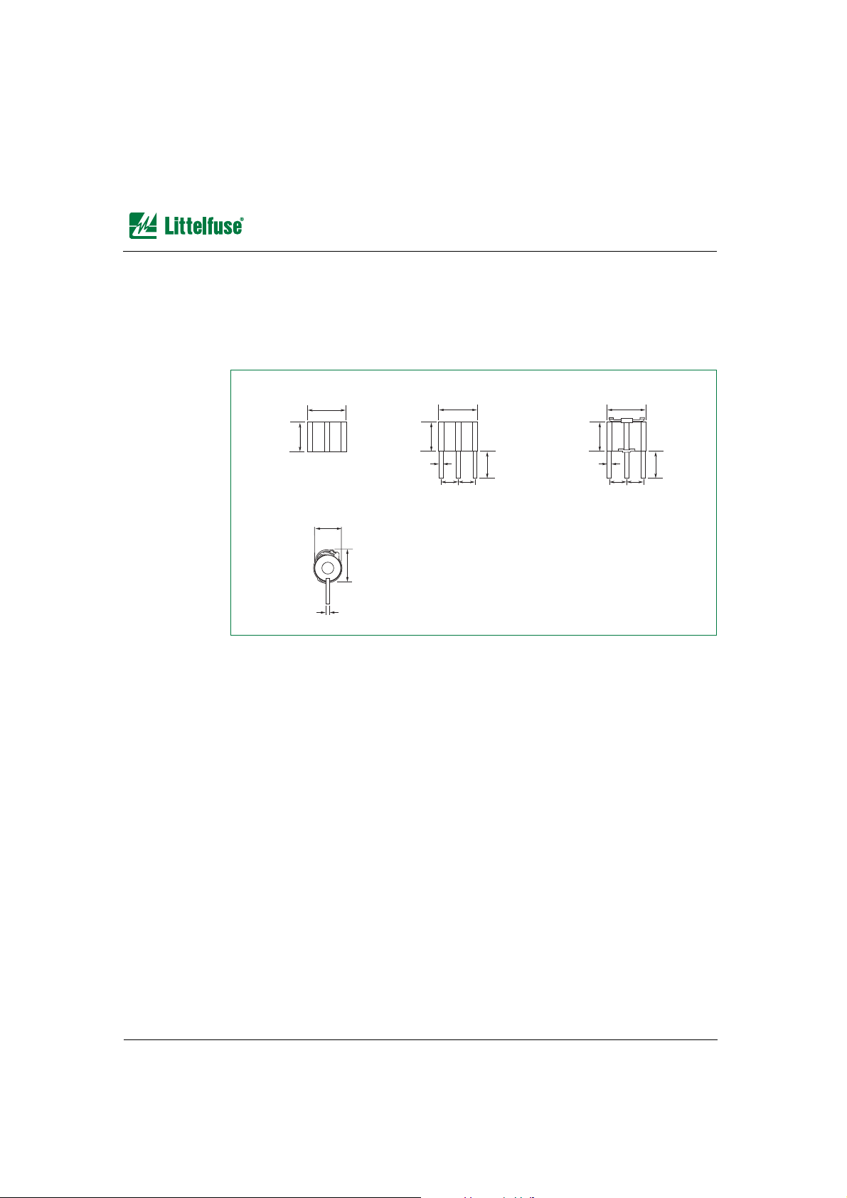
SIDACtor® Cell
The following illustration shows the dimensions of the SIDACtor cell.
0.105 Typ
Ø 0.156 ± 0.002
0.148 ± 0.002
0.156 ± 0.002 (Ref.)
0.0810 ± 0.0025
0.034 ± 0.001
0.0100 ± 0.0005
Sealant
Dimensions are in inches.
Page 20

www.littelfuse.com 9 - 20 © 2006 Littelfuse, Inc. • Telecom Design Guide
7HOH/LQN6XUIDFH0RXQW)XVH³3DFNDJH'LPHQVLRQV
7HOH/LQN6XUIDFH0RXQW)XVH³3DFNDJH'LPHQVLRQV
The following illustration shows the end view dimensions of a TeleLink fuse.
The following illustration shows the top view or side view dimensions of a TeleLink fuse.
The following illustration shows the footprint dimensions of a TeleLink fuse.
0.123
(3.12)
Dimensions are in inche
s
(and millimeters)
0.123
(3.12)
0.067
(1.70 typ)
0.123
(3.12)
0.397
(10.10)
0.067
(1.70 typ)
Dimensions are in inches
(and millimeters)
1.25A
T
L
F
0.240
(6.10)
0.128
(3.25)
0.135
(3.43)
0.496
(12.6)
Dimensions are in inches
(
and millimeters
)
Page 21

(OHFWURQLF)XVHV³3DFNDJH'LPHQVLRQV
Telecom Design Guide • © 2006 Littelfuse, Inc. 9 - 21 www.littelfuse.com
/GEJCPKECN&CVC
(OHFWURQLF)XVHV³3DFNDJH'LPHQVLRQV
2AG Slo-Blo® Fuse—229P / 230P Series
The following illustration shows the dimensions of the 2AG Slo-Blo Fuse—229P / 230P
series. The body is glass with nickel-plated brass fuse caps. Axial lead material is solder
coated copper.
NANO2® Fuse—451 / 453 Series
The following illustration shows the dimensions of a NANO2 Fuse—451 / 453 series. The
body is ceramic with tin-lead alloy or silver-plated caps. RoHS compliant terminations
(451L series) are gold over nickel-plated caps.
229P Series 230P Series
0.177
(4.5)
0.57
(14.48)
0.184 (4.7)
0.025
(0.635)
1.50
(38.1) TYP
Dimensions are in inches
(and millimeters).
0.57
(14.48)
F
7 A
0.270
(6.86)
0.124
(3.15)
0.116
(2.95)
0.077
(1.96)
0.106
(2.69)
0.057
(1.45)
0.240
(6.10)
Recommended pad layout
Dimensions are in inches
(and millimeters).
0.106
(2.69)
Page 22

www.littelfuse.com 9 - 22 © 2006 Littelfuse, Inc. • Telecom Design Guide
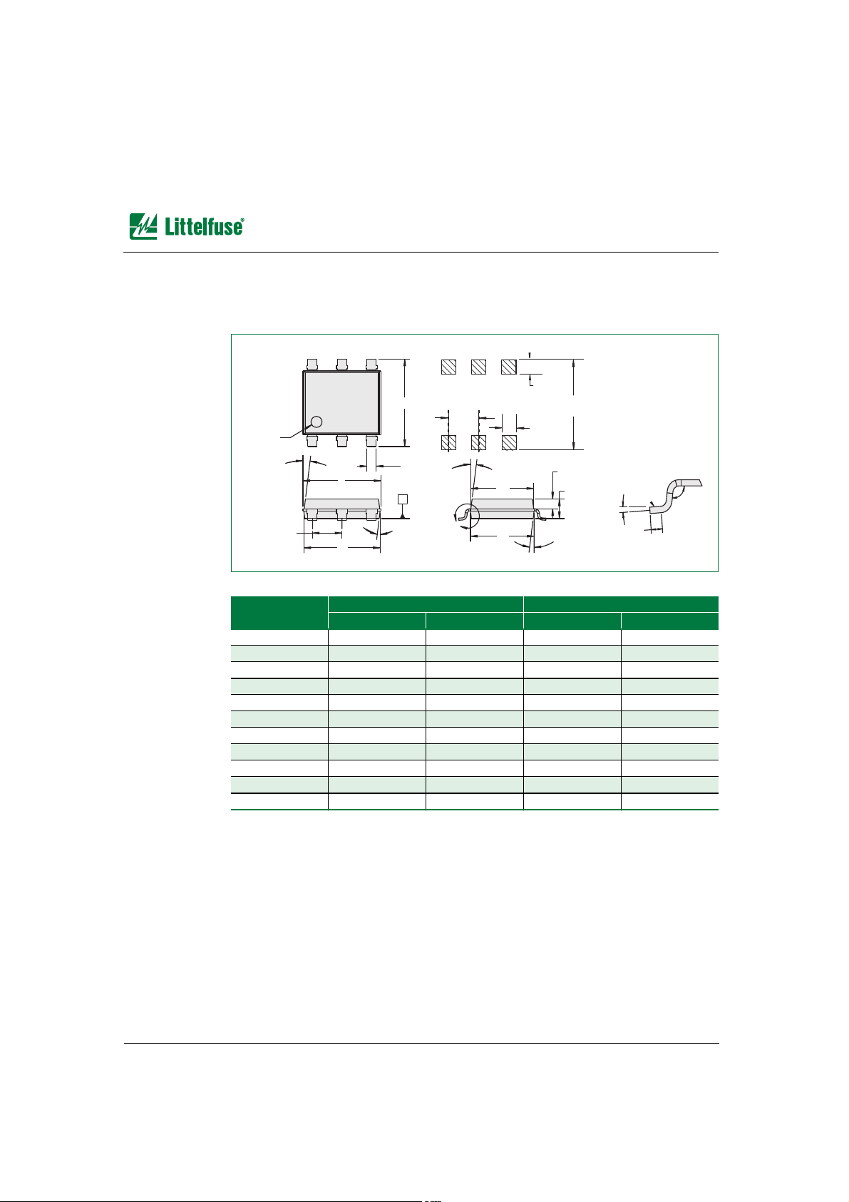
(OHFWURQLF)XVHV³3DFNDJH'LPHQVLRQV
NANO2® Fuse—452 / 454 Series
The following illustration shows the dimensions of a NANO2 Fuse—452 / 454 series. The
body is ceramic with tin-lead alloy or silver-plated caps. RoHS compliant terminations
(452L series) are gold over nickel-plated caps.
SMF OMNI-BLOK® Fuse Block—154 Series
The following illustration shows the dimensions of the SMF OMNI-BLOK Fuse Block—
154 series.
1 A
T
0.270
(6.86)
0.124
(3.15)
0.116
(2.95)
0.077
(1.96)
0.106
(2.69)
0.057
(1.45)
0.240
(6.10)
Recommended pad layout
F
Dimensions are in inches
(
and millimeters).
0.106
(2.69)
L
F
7 A
L
F
0.150
(3.81)
0.084
(
2.13
)
REF
0.418
(10.62)
0.167
(4.24)
0.383
(9.73) REF
0.150
(3.81)
0.198
(5.03)
155
FUSE
Recommended Pad Layout
Dimensions are in inche
s
(and millimeters).
Page 23

(OHFWURQLF)XVHV³3DFNDJH'LPHQVLRQV
Telecom Design Guide • © 2006 Littelfuse, Inc. 9 - 23 www.littelfuse.com
/GEJCPKECN&CVC
NANO2® 250V UMF Fuse—464 / 465Series
The following illustration shows the dimensions of the NANO2 250 V Fuse—464 / 465
series. The body is high-performance ceramic, and the terminations are silver-plated brass.
481 Series Alarm Indicating Fuse
The following illustration shows the dimensions of the 481 series alarm indicating fuse. The
body is polyphenylene sulfide (UL94V0), and the terminations are beryllium copper / tin
plated. Optional lens are nylon.
Reflow Solder
F
0.11
(2.8)
0.475
(12.1)
0.177
(4.5)
0.264
(6.7)
0.264
(6.8)
Wave Solder
0.14
(3.5)
AC250V
F500mAL
0.27
(6.9)
0.22
(5.6)
0.22
(5.6)
0.177
(4.5) Height
End CapTop View
Dimensions are in inche
s
(and millimeters).
0.90
(22.9) MIN
0.23
(5.8)
0.21
(5.3)
0.665
(16.9) MAX
0.46
(11.7)
0.70 (17.8)
0.77
(19.6)
0.84
(21.3)
REF
LENS
0.109
(2.77)
0.110
(2.79)
0.175
(4.45)
1–15 Amp 20 Amp *
* 20 A fuseholder must be used and is designed to accept all ratings up to 20 amps.
Fuse is keyed to prevent insertion in lower rated holders
Dimensions are in inches
(and millimeters).
Page 24

www.littelfuse.com 9 - 24 © 2006 Littelfuse, Inc. • Telecom Design Guide
(OHFWURQLF)XVHV³3DFNDJH'LPHQVLRQV
482 Series Alarm Indicating Fuseholder
The following illustration shows the 482 series alarm indicating fuseholder. The body is
black phenolic. The fuse terminals are tin-plated beryllium copper, and the alarm terminal is
tin-plated brass.
Flush side options
available for PCB and
panel mount version
Five-pole Holder Assembl
y
with Flush Option
Page 25

'&3RZHU)XVHV³3DFNDJH'LPHQVLRQV
Telecom Design Guide • © 2006 Littelfuse, Inc. 9 - 25 www.littelfuse.com
/GEJCPKECN&CVC
'&3RZHU)XVHV³3DFNDJH'LPHQVLRQV
L17T Series
The following illustration shows the dimensions of the L17T series telecommunications
power fuse.
Contact Littelfuse for characteristic curves.
Dimensions
70 A – 250A 300 A – 800 A 1000 A – 1200 A
Inches Millimeters Inches Millimeters Inches Millimeters
A 1.156 29.4 1.25 31.8 1.344 34
B 1.875 47.6 1.938 49.2 — —
C 2.188 55.6 2.563 65.1 — —
D — 67.5 3.5 88.9 4.063 103.12
E 1.656 25.4 1.5 38.1 — —
F 0.875 22.2 1 25.4 1.5 38.1
G 0.313 7.9 0.406 10.3 — —
H 0.188 4.8 0.25 6.35 0.25 6.35
A
B
C
D
F
G
E
H
Page 26

www.littelfuse.com 9 - 26 © 2006 Littelfuse, Inc. • Telecom Design Guide
'&3RZHU)XVHV³3DFNDJH'LPHQVLRQV
TLN Series
The following illustrations show the dimensions of the TLN series telecommunications
power fuse. (The TLN series replaces competitors’ TPN and TGN series.)
Contact Littelfuse for characteristic curves.
Figure 1
Dimensions
1A – 30A 35 A – 60 A
Inches Millimeters Inches Millimeters
A 2 50.8 3 76.2
B 0.5 12.7 0.75 19.1
C 0.5 12.7 0.625 15.9
D 0.563 14.3 0.813 20.6
E 0.078 2 0.094 2.4
F 0.156 4 0.188 4.8
G 0.375 9.5 0.625 15.9
H — — — —
J————
K — — — —
Figure 2
Dimensions
70 A – 100 A 110 A – 200 A 225 A – 400 A 450 A – 600 A
Inches Millimeters Inches Millimeters Inches Millimeters Inches Millimeters
A 5.875 149.2 7.125 181 8.625 219.1 10.375 263.5
B 1 25.4 1.5 38.1 2 50.8 2.5 63.5
C 1.063 27 1.469 37.3 1.938 49.2 2.375 60.3
D 1.063 27 1.594 40.5 2.094 53.2 2.594 65.9
E 0.125 3.2 0.188 4.8 0.25 6.4 0.25 6.4
F 0.75 19.1 1.125 28.6 1.625 41.3 2 50.8
G 1.25 31.6 1.844 46.8 2.344 59.5 2.844 72.2
H 0.25 6.4 0.438 11. 1 0.625 15.9 0.75 19.1
J 0.281 7.1 0.281 7.1 0.406 10.3 0.531 13.5
K 0.5 12.7 0.688 17.5 0.938 23.8 1.125 28.6
F
A
Figure 1
D
G
E
C
B
D
J
F
Figure 2
A
B
C
A
H
K
Page 27

'&3RZHU)XVHV³3DFNDJH'LPHQVLRQV
Telecom Design Guide • © 2006 Littelfuse, Inc. 9 - 27 www.littelfuse.com
/GEJCPKECN&CVC
TLSSeries
The following illustration shows the dimensions of the TLS series telecommunications
power fuse. (The TLS series replaces competitors’ TPS and TGS series.)
Note: Contact Littelfuse for characteristic curves and additional mounting configurations.
1.260
0.370
REF
0.880
o.563
TLS TLS-V
TLS-LBTLS-L
0.740
0.195
REF
1.740
0.382
REF
1.367
1.58
0.032
Dimensions are in inches.
Page 28

www.littelfuse.com 9 - 28 © 2006 Littelfuse, Inc. • Telecom Design Guide
'&3RZHU)XVHV³3DFNDJH'LPHQVLRQV
LTFD Series
The following illustration shows the dimensions of the LTFD 6001 series (0 A – 800 A)
telecommunications power fuse. Stud size is as follows:
• 0.75 – 16x3.5 inches
• 0.875 – 14x3.5 inches
Dimensions are for reference only.
Page 29

'&3RZHU)XVHV³3DFNDJH'LPHQVLRQV
Telecom Design Guide • © 2006 Littelfuse, Inc. 9 - 29 www.littelfuse.com
/GEJCPKECN&CVC
The following illustration shows the dimensions of the LTFD 1200 series (900 A – 1200 A)
telecommunications power fuse. Stud size is 1.12 – 12x4 inches.
Dimensions are for reference only.
Page 30

www.littelfuse.com 9 - 30 © 2006 Littelfuse, Inc. • Telecom Design Guide
'&3RZHU)XVHV³3DFNDJH'LPHQVLRQV
LTFD 101 Series
The following illustration shows the dimensions of the LTFD 101 series telecommunications
power fuse. Contact Littelfuse for additional options and dimensions.
Dimensions are for reference only.
6-32 INSERT
0.75"
2.50"
2.062"
1.940"
2.00" 0.85"
LOAD
LINE
3.75"
0.305" Dia.
Bullet Ter minal
Alarm pin
0.02" x 0.11"
position optional
C
L
Page 31

6XPPDU\RI3DFNLQJ2SWLRQV
Telecom Design Guide • © 2006 Littelfuse, Inc. 9 - 31 www.littelfuse.com
/GEJCPKECN&CVC
6XPPDU\RI3DFNLQJ2SWLRQV
Package Type Description
Packing
Quantity
Added
Suffix
Industry
Standard
SL1122A Series
Bulk Pack (10 x Trays of 100) 1000 Standard EIA-RS-296
SL0902A Series
Tape and Reel Pack 1500 SM EIA-481-2
Bulk Pack 1000 C N/A
SL1002A Series
Tape and Reel Pack
(tape width 16 mm)
1000 SM EIA-481-2
Bulk Pack 1000 C N/A
SL1003A Series
Tape and Reel Pack 700 SM EIA-481-2
10 x Trays of 100 1000 R N/A
Bulk Pack 1000 C N/A
SL1011A/B Series
Tape and Reel Pack 1000 A EIA-RS-296
Bulk Pack 1000 C N/A
Bulk Pack (10 x Trays of 100) 1000 Formed
Options
N/A
SL1021A/B Series
Bulk Pack (10 x Trays of 100) 1000 R, RF, RS EIA-RS-296
SL1024A/B Series
Bulk Pack (10 x Trays of 100) 1000 R, RF, RS N/A
Page 32

www.littelfuse.com 9 - 32 © 2006 Littelfuse, Inc. • Telecom Design Guide
6XPPDU\RI3DFNLQJ2SWLRQV
SL1411A Series
Tape and Reel Pack 1000 A EIA-296
Bulk Pack 1000 C N/A
DO-214AA
SA, SB, SC, SD, including MC
Embossed Carrier Reel Pack 2500 RP EIA-481-1
TO-92
EA, EB, EC, including MC
Note: Standard lead spacing for TO-92
reel pack is 0.200” (RP2).
Bulk Pack 2000 Standard N/A
Tape and Reel Pack 2000 RP1, RP2 EIA-468-B
Ammo Pack 2000 AP EIA-468-B
T10A [DO-15] Tape and Reel Pack 5000 RP EIA-468-B
Bulk Pack 1000 N/A N/A
T10B [DO-201AD] Tape and Reel Pack 1000 RP EIA-468-B
Bulk Pack 500 N/A N/A
[T10C] Bulk Pack (10 x Trays of 100) 1000 N/A N/A
Modified MS-013 Tape and Reel Pack 1500 RP EIA-481-1
Tube Pack 50 per tube,
10 tubes per container
TP EIA-481-1
Package Type Description
Packing
Quantity
Added
Suffix
Industry
Standa rd
3-lead
Page 33

6XPPDU\RI3DFNLQJ2SWLRQV
Telecom Design Guide • © 2006 Littelfuse, Inc. 9 - 33 www.littelfuse.com
/GEJCPKECN&CVC
TO-220
AA, AB, AC, AD
Bulk Pack 500 Standard N/A
Tape and Reel Pack 700 RP EIA-468-B
Bulk Pack for Type 60 lead form 500 BP N/A
Tape and Reel Pack for
Type 61 lead form
700 RP EIA-468-B
Tube Pack 50 per tube,
10 tubes per container
TP EIA-468-B
TO-220AB Bulk Pack 500 Standard N/A
TO-218
ME
Bulk Pack 250 Standard N/A
TO-263
D
2
PAK
Tube Pack 50 per tube,
10 tubes per container
TP
Tape and Reel Pack 500 RP EIA-481-2
MS-012 Tape and Reel Pack 5000 Standard EIA-481-1
SIDACtor® Cell Bulk Pack (25 x Trays of 200) 5000 — N/A
Package Type Description
Packing
Quantity
Added
Suffix
Industry
Standa rd
Type 61Type 60
Page 34

www.littelfuse.com 9 - 34 © 2006 Littelfuse, Inc. • Telecom Design Guide
6XPPDU\RI3DFNLQJ2SWLRQV
TeleLink® Surface Mount Fuse
461 Series
Embossed Carrier Reel Pack 2500 RP EIA-481-B
Bulk Pack 5000 BP N/A
Tape and Reel Pack (16 mm) 2500 ERT16
229P / 230P Series Bulk Pack 1000 M EIA-296
Tape and Reel Pack 1500 DRT1 EIA-296
Tape and Reel Pack 2500 ERT1 EIA-296
451 / 453 Series Tape and Reel Pack (12 mm) 1000 MR EIA-RS481-1
Tape and Reel Pack (12 mm) 5000 NR EIA-RS481-1
452 / 454 Series Tape and Reel Pack (12 mm) 1000 MR EIA-RS481-1
Tape and Reel Pack (12 mm) 5000 NR EIA-RS481-1
154 Series Tape and Reel Pack (16 mm) 1500 DR EIA-481
464 Series Tape and Reel Pack (24 mm) 1500 DR EIA-RS481-1
465 Series Tape and Reel Pack (24 mm) 1500 DR EIA-RS481-1
481 Series Bulk Pack Five-pack V
Bulk Pack 100-piece box H
Package Type Description
Packing
Quantity
Added
Suffix
Industry
Standa rd
Page 35

6XPPDU\RI3DFNLQJ2SWLRQV
Telecom Design Guide • © 2006 Littelfuse, Inc. 9 - 35 www.littelfuse.com
/GEJCPKECN&CVC
482 Series Contact Littelfuse for packing and ordering information.
L17T Series Contact Littelfuse for packing and ordering information.
TLN Series Contact Littelfuse for packing and ordering information.
TLS Series Contact Littelfuse for packing and ordering information.
LTFD Series Contact Littelfuse for packing and ordering information.
LTFD 101 Series Contact Littelfuse for packing and ordering information.
Package Type Description
Packing
Quantity
Added
Suffix
Industry
Standa rd
Page 36

www.littelfuse.com 9 - 36 © 2006 Littelfuse, Inc. • Telecom Design Guide
3DFNLQJ2SWLRQV
3DFNLQJ2SWLRQV
SL1122A Series
Tape and reel packing options meet all specifications as set forth in EIA-481-1. Bulk pack
quantity is 1000 (10 trays of 100). Depth of tray with lid is 22 mm; width of tray is
222 mm x 222 mm.
SL0902A Series
Tape and reel packing options meet all specifications as set forth in EIA-481-2. Standard
reel pack quantity is 1500. Bulk pack quantity is 1000.
Page 37

3DFNLQJ2SWLRQV
Telecom Design Guide • © 2006 Littelfuse, Inc. 9 - 37 www.littelfuse.com
/GEJCPKECN&CVC
SL1002A Series
Tape and reel packing options meet all specifications as set forth in EIA-481-2. Standard
reel pack quantity is 1000. Bulk pack quantity is 1000.
SL1003A Series
Tape and reel packing options meet all specifications as set forth in EIA-481-2. Standard
reel pack quantity is 700. Bulk pack quantity is 1000.
Page 38

www.littelfuse.com 9 - 38 © 2006 Littelfuse, Inc. • Telecom Design Guide
3DFNLQJ2SWLRQV
SL1011A/BSeries
Tape and reel packing options meet all specifications as set forth in EIA-296. Standard reel
pack quantity is 1000. Bulk pack quantity is 1000.
SL1021A/BSeries
Bulk pack quantity is 1000 (10 trays of 100). Depth of tray with lid is 22 mm; width of tray is
222 mm x 222 mm.
SL1024A/BSeries
Bulk pack quantity is 1000 (10 trays of 100). Depth of tray with lid is 22 mm; width of tray is
222 mm x 222 mm.
SL1411A Series
Tape and reel packing options meet all specifications as set forth in EIA-296. Standard reel
pack quantity and bulk pack quantity for axial-leaded devices is 1000 pieces.
Contact Littelfuse for surface mount packaging information.
Page 39

3DFNLQJ2SWLRQV
Telecom Design Guide • © 2006 Littelfuse, Inc. 9 - 39 www.littelfuse.com
/GEJCPKECN&CVC
DO-214AA
Tape and reel packing options meet all specifications as set forth in EIA-481-1. Standard
reel pack quantity is 2500. Bulk pack quantity is 1000.
The following illustration shows the DO-214AA component orientation for P0641S, P0721S,
P0901S, P1101S, P1301S, P1701S:
The following illustration shows the modified DO-214 tape and reel:
3-lead
0.472
(12.0)
0.36
(9.2)
0.315
(8.0)
0.157
(4.0)
0.49
(12.4)
0.512 (13.0) Arbor
Hole Dia.
12.99
(330.0)
Dimensions are in inches
(and millimeters).
Direction of Feed
0.059
DIA
(1.5)
Cover tape
Cathode
0.472
(12.0)
0.360
(9.2)
0.315
(8.0)
0.157
(4.0)
Pin 2
Anode
Cathode
Pin 1
Gate
Pin 3
Dimensions are in inches
(and millimeters).
Page 40

www.littelfuse.com 9 - 40 © 2006 Littelfuse, Inc. • Telecom Design Guide
3DFNLQJ2SWLRQV
TO-92
Tape and reel packing options meet all specifications as set forth in EIA-468-B. Standard
reel pack quantity is 2000.
Notes:
• Part number suffix RP2 denotes 0.200” (5 mm) lead spacing and is Littelfuse’s default value.
• Part number suffix RP1 denotes 0.100” (2.54 mm) lead spacing and is available upon request.
The following figure shows the TO-92 Ammo Pack option:
Flat Down
1.62
(41.2)
0.708
(18.0)
0.354
(9.0)
0.236
(6.0)
0.02
(0.5)
0.50
(12.7)
14.17
(360.0)
0.20
(5.08)
0.125 (3.2) MAX
1.27
(32.2)
1.97
(50.0)
0.50
(12.7)
0.25
(6.35)
Dimensions are in inches
(and millimeters).
Direction of Feed
0.157
DIA
(4.0)
Flat down
25 Devices per fold
0.708
(18.0)
1.27
(32.2)
0.125 (3.2) MAX
1.62
(41.2)
MAX
0.50
(12.7)
0.354
(9.0)
0.236
(6.0)
0.02 (0.5)
0.20 (5.08)
0.50
(12.7)
0.25
(6.35)
Direction of Feed
Dimensions
are in inches
(and millimeters).
1.85
(47.0)
13.3
(338.0)
12.2
(310.0)
1.85
(47.0)
0.157
DIA
(4.0)
Page 41

3DFNLQJ2SWLRQV
Telecom Design Guide • © 2006 Littelfuse, Inc. 9 - 41 www.littelfuse.com
/GEJCPKECN&CVC
T10A
Tape and reel packing options for the T10A meet all specifications as set forth in EIA-468-B.
Standard reel pack quantity is 5000. Bulk pack quantity is 1000.
Off Center
Both Sides
0.88
0.24
0.18
2.0
0.07
3.4
14
2.7
0.6
Top View
Front View
Label
Recess Depth Max 0.75"
2.55
Direction of Feed
Dimensions are
in inches.
Page 42

www.littelfuse.com 9 - 42 © 2006 Littelfuse, Inc. • Telecom Design Guide
3DFNLQJ2SWLRQV
T10B
Tape and reel packing options for the T10B meet all specifications as set forth in EIA-468-B.
Standard reel pack quantity is 1000. Bulk pack quantity is 500.
Off Center
Both Sides
0.84
0.24
0.35
2.0
0.085
3.4
14
2.7
0.6
Top View
Front View
Label
Recess Depth Max 0.75"
2.55
Direction of Feed
Dimensions are
in inches.
Page 43

3DFNLQJ2SWLRQV
Telecom Design Guide • © 2006 Littelfuse, Inc. 9 - 43 www.littelfuse.com
/GEJCPKECN&CVC
T10C
The following illustration shows the tray for the T10C. Standard tray quantity is 1000 per box
(10 trays of 100 each).
0.602 to Index
8.900
A
A
8.850
BB
R.150 4X
Top Surface of
Area Recessed
by 0.100
0.855 TYP.
0.846
TYP.
A - - - A
3X Scale
B - - - B
3X Scale
0.000
R.030 TYP.
0.512
0.587
0.292
0.032
0.259
0.000
Index
0.799
0.091
Top Packaging Tray
0.098
0.288
R.020 TYP.
0.492
0.533
0.000
0.602
0.000
Index
Center
of Pocket
[Material Thickness: 0.010 ]
A - - - A
3X Scale
B - - - B
3X Scale
Bottom Packaging Tray
0.855
TYP.
Center
of Pocket
0.587
REF.
0.602
REF.
A
A
BB
Top Surface of
Area Recessed
by 0.100
0.846
TYP.
Center
of
Pocket
8.850
0.423
R.150
R.250
Unless specified, provide
minimum draft angle.
0.428
0.000
R.120
R.030
R.020
R.030
0.372
R.070
R.020
0.070
0.884
0.780
(to cent. of rad.)
0.663
(to cent. of rad.)
0.297
(to cent. of rad.)
0.095
(to cent. of rad.)
0.000
(to cent. of rad.)
Center of
Pocket
R.020 TYP.
0.000
0.428
R.030
0.382
0.312
0.290
0.163
0.000
[Material Thickness: 0.010 ]
Dimensions are
in inches.
Page 44

www.littelfuse.com 9 - 44 © 2006 Littelfuse, Inc. • Telecom Design Guide
3DFNLQJ2SWLRQV
Modified MS-013Six-pin
Tape and reel packing options meet all specifications as set forth in EIA-468-B. Standard
reel pack quantity is 1500.
The following illustration shows the tube pack:
2
3
6
5
4
Direction of Feed
0.700
(17.8)
.512 (13.0) Arbor
Hole Dia.
12.99
(330)
.630
(16.0)
Dimensions are in inches
(and millimeters)
Component/Tape Layou
t
1,500 Devices per Reel
.472
(12.0)
.157
(4.0)
Interior of the Tube
.045
(1.14)
.165
(4.19)
.150
(3.81)
90˚
.525
(13.34)
A
.225
(5.72)
Message Location
.310
(7.87)
.108
(2.74)
.005
20.000 ± .030
(508.00 ± 0.76)
.020 ± .005
(0.51 ± 0.13)
WALL TYP.
.110
(2.79)
A
6
Dimensions are in inches
(and millimeters)
Page 45

3DFNLQJ2SWLRQV
Telecom Design Guide • © 2006 Littelfuse, Inc. 9 - 45 www.littelfuse.com
/GEJCPKECN&CVC
Modified TO-220
Tape and reel packing options meet all specifications as set forth in EIA-468-B. Standard
reel pack quantity is 700.
The following illustration shows the tube pack:
Type 61
1.626
(41.15)
0.720
(18.29)
0.360
(9.14)
0.240
(6.10)
0.019
(0.5)
0.750 ± 0.010
(19.05 ± 0.25)
0.500
(12.7)
0.100
(2.54)
0.100
(2.54)
14.173
(360.0)
Component/Tape Layout
Standard Reel pack (RP)
Dimensions are in inches
(and millimeters).
1.968
(50.0)
Direction of Feed
REF
22.0 ± .2
(559 ± 5)
.220
(5.58)
.160
(4.06)
1.300
(136.25)
1.250 ± .015
(31.75)
.630 ± .015
(16.00 ± 0.38)
.140
(3.56)
.025 ± .005
(0.64 ± 0.13)
TYP. Wall
Dimensions are in inches
(and millimeters)
Page 46

www.littelfuse.com 9 - 46 © 2006 Littelfuse, Inc. • Telecom Design Guide
3DFNLQJ2SWLRQV
TO-263
Tape and reel packing options meet all specifications as set forth in EIA-481-2. Standard
reel pack quantity is 500.
Gate
MT1 / Cathode
MT2 / Anode
0.512 (13.0) Arbor
Hole Dia.
0.945
(24.0)
0.63
(16.0)
1.01
(25.7)
12.99
(330.0)
0.827
(21.0)
0.157
(4.0)
Direction of Feed
Dimensions
are in inches
(and millimeters).
*
*
Cover tape
0.059
DIA
(1.5)
Page 47

3DFNLQJ2SWLRQV
Telecom Design Guide • © 2006 Littelfuse, Inc. 9 - 47 www.littelfuse.com
/GEJCPKECN&CVC
TeleLink®Surface Mount Fuse
The following illustration shows the dimensions of the 24mmTeleLink embossed carrier tape.
4˚ Max.
Section 'A'-'A'
.0135±.0005
(.343±.013)
+.012
-.004
+.30
-.10
.945
(24.00)
8˚ Max.
.436±.004
(11.07±.10)
.453±.004
(11.50±.10)
.124±.004
(1.75±.10)
.436±.004
(3.15±.10)
.157±.004
(4.00±.10)
.059±.010
(1.50±.25)
Dia.
.079±.004
(2.00±.10)
.059±.004
(1.50±.10)
Dia.
'A'
'B'
'A'
'B'
.315±.004
(8.00±.10)
.129±.004
(3.28±.10)
24 mm Black
Anti-static Carrier Tape
Dimensions are in inches
(and millimeters)
Page 48

www.littelfuse.com 9 - 48 © 2006 Littelfuse, Inc. • Telecom Design Guide
3DFNLQJ2SWLRQV
The following illustration shows the dimensions of the TeleLink 16 mm carrier tape.
Embossment
(contains fuse)
1.75 ±0.1
(0.069) ±0.004
Dimensions are in inches
(and millimeters).
Direction of Feed
16.0 +0.3/-0.1
(0.630) +0.012/-0.004
3.3 ±0.1
(0.130) ±0.004
0.75
(0.030) MIN
8.0 ±0.1
(0.315) ±0.004
10°
MAX
10°
MAX
Ø1.5 ±0.1
(0.059) ±0.004
2.0 ±0.1
(0.079) ±0.004
4.0 ±0.1
(0.157) ±0.004
R 0.3
(0.012) MIN
R 0.3
(0.012)
MAX
R 0.3
(0.012)
MAX
3.6
(0.142)
MAX
Ø1.5 ±0.1
(0.059) ±0.004
3° MAX
0.3
(0.012) MAX
3.3 ±0.1
(0.130) ±0.004
14.25
(0.561) MIN
10.6 ±0.1
(0.417) ±0.004
7.5 ±0.1
(0.295) ±0.004
16 mm Carrier Tape
Page 49

3DFNLQJ2SWLRQV
Telecom Design Guide • © 2006 Littelfuse, Inc. 9 - 49 www.littelfuse.com
/GEJCPKECN&CVC
The following illustration shows the TeleLink 13-inch (330 mm), injection-molded, highimpact, anti-static, white, plastic reel. Material conforms to EIA-481-1. Surface resistivity is
1011
Ω/square. Materials comply with ASTM D-257.
Access hole
greater than
40.00 at slot
1.575 location
.512±.008
(13.00±.20)
Arbor hole
2.362±.039
(60.00±1.00)
Hub dia.
2.00
.079
(Drive Spokes)
min.
.795
(20.20)
min.
Tape slot depth
greater than .394 (10.00)
12.992
(330.00)
Max dia.
1.19
(30.40)
Measured
at hub
1.00±.069
(25.65±1.75)
Measured at
outer edge
.197±.020
(5.00±.51)
Tape starter slot
.960
(24.40)
Measured
at hub
+.079
-.00
+2.00
-.00
Dimensions are in inches
(and millimeters)
Page 50

www.littelfuse.com 9 - 50 © 2006 Littelfuse, Inc. • Telecom Design Guide
3DFNLQJ2SWLRQV
229P / 230P Series
Tape and reel packing options meet all specifications as set forth in EIA-296. Standard reel
pack quantity is 1500 and 2500. Bulk pack quantity is 1000.
0.0161
(0.250)
A
0.031
(0.787) MAX
0.400
(10.16)
0.400
(10.16)
3.15 (80.0) TYP
Direction of Feed
10.0 - 14.0
(254.0 - 356.0)
Dimensions
are in inches
(and millimeters).
Tape Spacing (A)
RT1 = 2.062 (52.4)
RT2 = 2.50 (63.5)
RT3 = 2.874 (73.0)
RT4 = 3.02 (76.71)
Page 51

/HDG)RUP2SWLRQV
Telecom Design Guide • © 2006 Littelfuse, Inc. 9 - 51 www.littelfuse.com
/GEJCPKECN&CVC
/HDG)RUP2SWLRQV
Modified TO-220 Type 60
Dimension
Inches Millimeters
Min Max Min Max
A 0.485 12.32
B 0.162 0.192 4.11 4.88
C 0.162 0.192 4.11 4.88
0.324
(8.23)
0.047
(1.19)
Dia. ref.
0.177
(4.50)
.645±.025
(16.38±0.64)
30˚
Dimensions are in inches
(and millimeters)
A
B
C
Page 52

www.littelfuse.com 9 - 52 © 2006 Littelfuse, Inc. • Telecom Design Guide
/HDG)RUP2SWLRQV
Modified TO-220 Type 61
Modified TO-220 Type 62
Dimension
Inches Millimeters
Min Max Min Max
A 0.030 0.060 0.762 1.52
Dimension
Inches Millimeters
Min Max Min Max
A 0.172 0.202 4.37 5.13
B 0.440 0.460 11.1 8 11 .68
C 0.120 0.130 3.05 3.30
A
PIN 1
PIN 3
5˚ TYP.
A
B
C
 Loading...