

Page 1
POLY-FUSE® Resettable PTCs
Surface Mount > 1210L Series
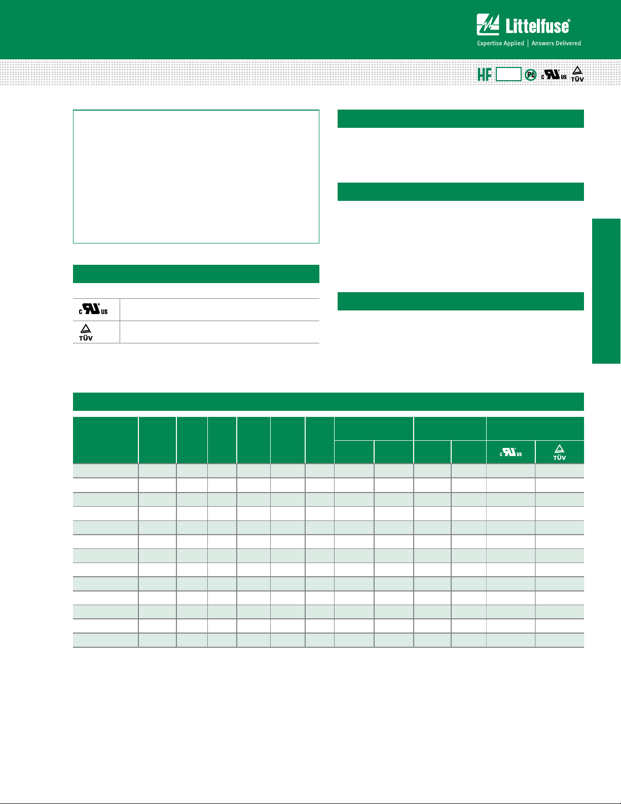
1210L Series
Agency Approvals
AGENCY AGENCY FILE NUMBER
E183209
R50119118
RoHS
Description
The 1210L Series PTC provides surface mount overcurrent
protection for applications where space is at a premium
and resettable protection is desired.
Features
• RoHS compliant, lead-free
and halogen-free
• Fast response to fault
currents
• Low resistance
• Low-prole
• Compatible with high
temperature solders
• Compact design saves
board space
Applications
• USB peripherals
• Disk drives
• CD-ROMs
• PC motherboards - plug
and play protection
• Mobile phones - battery
and port protection
• PDAs / digital cameras
• Game console port
protection
1210L Series
Electrical Characteristics
Maximum Time
Part Number Marking
I
hold
(A)
I
V
(A)
trip
(Vdc)
max
I
(A)
max
P d
typ.
(W)
To Trip
Current
(A)
Time
(Sec.)
1210L005 A 0.05 0.15 30 10 0.60 0.25 1.50 3.600 50.00
1210L010 B 0.10 0.30 30 10 0.60 0.50 1.50 1.600 15.00
1210L020 C 0.20 0.40 30 10 0.60 8.00 0.02 0.800 5.000
1210L035 E 0.35 0.70 6 100 0.60 8.00 0.20 0.320 1.300
1210L050 F 0.50 1.0 0 13.2 100 0.60 8.00 0.05 0.250 0.900
1210L075 G 0.75 1.50 6 100 0.60 8.00 0.10 0.130 0.400
1210L075/24 G2 0.75 1.50 24 100 0.60 8.00 0.10 0.130 0.400
1210L110/12 H1 1. 10 2.20 12 100 0.6 8.00 0.10 0.060 0.210
1210L110/16 HF 1. 10 2.20 16 100 0.6 8.00 0.10 0.060 0.210
1210L110TH H 1. 10 2.20 8 100 0.60 8.00 0.10 0.060 0.210
1210L150TH K 1.50 3.00 6 10 0 0.80 8.00 0.30 0.040 0.110
1210L175 V 1.75 3.50 6 10 0 0.80 8.00 0.60 0.020 0.080
1210L200 L 2.00 4.00 6 10 0 0.80 8.00 1. 00 0.015 0.070
I
= Hold current: maximum current device will pass without tripping in 20°C still air.
hold
= Trip current: minimum current at which the device will trip in 20°C still air.
I
trip
= Maximum voltage device can withstand without damage at rated current (I max)
V
max
= Maximum fault current device can withstand without damage at rated voltage (V
I
max
Caution: Operation beyond the specied rating may result in damage and possible arcing and ame.
P d = Power dissipated from device when in the tripped state at 20°C still air.
= Minimum resistance of device in initial (un-soldered) state.
R
min
= Typical resistance of device in initial (un-soldered) state.
R
typ
)
max
= Maximum resistance of device at 20°C measured one hour after tripping or reflow
R
1max
soldering of 260°C for 20 sec.
Resistance
R
min
(Ω)
Agency
Approvals
R
1max
(Ω)
X X
X X
X X
X X
X X
X X
X X
X X
X X
X X
X X
X X
X X
© 2013 Littelfuse, Inc.
Specifications are subject to change without notice.
Revised: 11/05/13
Page 2
POLY-FUSE® Resettable PTCs
0.01
0.1
1
10
100
1000
10000
100000
0.1 110100
Current in Amperes
Time in Seconds
1812L
0.10A
0.14A
0.20A
0.50A
0.75A/33V
0.75A/24V
0.75A
1.10A/16V
1.10A/33V
1.10A
1.25A
1.25A/6V
1.50A/12V
1.50A
1.50A/24V
1.60A/12V
1.60A
1.60A/8V
2.00A
2.60A
11
Surface Mount > 1210L Series
Temperature Rerating
Ambient Operation Temperature
-40°C -20°C 0°C 20°C 40°C 50°C 60°C 70°C 85°C
Part Number Hold Current (A)
1210L005 0.08 0.07 0.06 0.05 0.04 0.04 0.03 0.03 0.02
1210L010 0.16 0.14 0.12 0.10 0.08 0.07 0.06 0.05 0.03
1210L020 0.29 0.26 0.22 0.20 0.16 0.14 0.13 0.11 0.08
1210L035 0.47 0.45 0.40 0.35 0.33 0.28 0.24 0.21 0.18
1210L050 0.76 0.67 0.58 0.50 0.43 0.40 0.36 0.32 0.28
1210L075 1. 0 0 0.97 0.86 0.75 0.64 0.59 0.54 0.48 0.40
1210L075/24 1. 1 3 1. 0 0 0.88 0.75 0.61 0.54 0.47 0.41 0.35
1210L110/12 1.65 1.47 1.27 1. 10 0.92 0.83 0.73 0.63 0.52
1210L110/16 1.65 1.47 1.27 1. 10 0.92 0.83 0.73 0.63 0.52
1210L110TH 1.69 1.48 1.29 1. 10 0.88 0.76 0.65 0.57 0.43
1210L150TH 2.13 1.92 1.71 1.50 1.26 1. 1 4 1. 01 0.89 0.71
1210L175 2.42 2.22 1.98 1.75 1.52 1.35 1.23 1.05 0.84
1210L200 2.60 2.44 2.35 2.00 1.78 1.67 1.50 1.45 1. 10
Notes: The temperature rerating data is only for reference, please contact Littelfuse technical support for detail temperature rerating information.
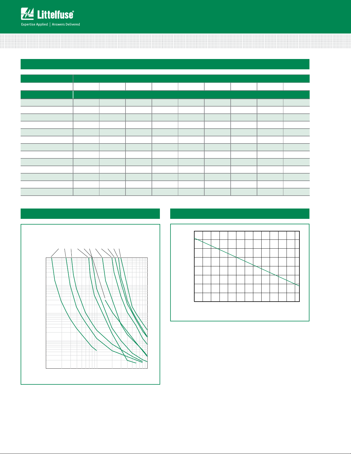
Average Time Current Curves
0.05A
0.10A
0.20A
0.35A
0.50A
0.75A
0.75A/24
1. 10 A
1.50A
1.75A
2.00A
100
10
1
Time in Seconds
0.1
0.01
0.1
Current in Amperes
The average time current curves and Temperature Rerating curve performance is affected
by a number or variables, and these curves provided as guidance only. Customer must
verify the performance in their application.
1210L
0
Temperature Rerating Curve
170%
150%
130%
110%
90%
70%
50%
Percentage of Rated Current
30%
10%
-40 -30 -20 -10010 20 30 40 50 60 70 80 85
Temperature (°C)
Specifications are subject to change without notice.
© 2013 Littelfuse, Inc.
Revised: 11/05/13
Page 3
POLY-FUSE® Resettable PTCs
Surface Mount > 1210L Series
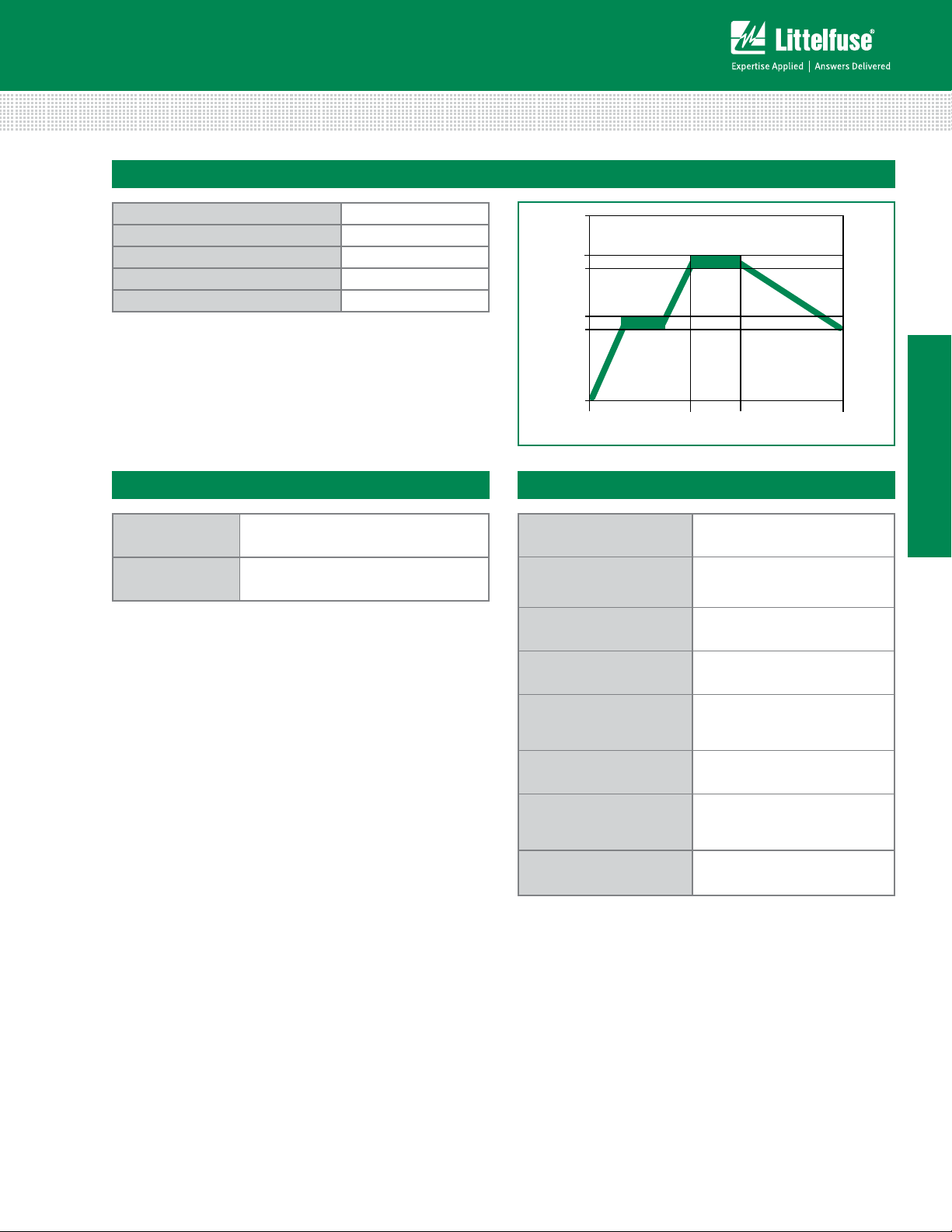
Soldering Parameters
Condition Reflow
Peak Temp/ Duration Time 260°C / 10 Sec
Time above liquids (TAL) 220°C 60 Sec ~ 100 Sec
Preheat 120°C~ 180°C 50 Sec ~ 150 Sec
Storage Condition 0°C~35°C,
• Recommended reow methods: IR, vapor phase oven, hot air
oven, N
environment for lead–free
2
• Recommended maximum paste thickness is 0.25mm (0.010 inch)
• Devices can be cleaned using standard industry methods and
solvents.
Note: If reow temperatures exceed the recommended prole,
devices may not meet the performance requirements.
<
70%RH
=
260
220
180
120
Temperature (°C)
Preheating
0
50 to 150
Soldering Cooling
60 to 100
Time(s)
120
1210L Series
Physical Specifications
Terminal Material
Lead Solderability
Solder-Plated Copper (Solder Material:
Matte Tin (Sn))
Meets EIA Specication RS186-9E,
ANSI/J-STD-002 Category 3.
Environmental Specifications
Operating/Storage
Temperature
Maximum Device Surface
Temperature in Tripped
State
Passive Aging
Humidity Aging
Thermal Shock
Solvent Resistance
Vibration
Moisture Level Sensitivity Level 1, J–STD–020C
-40°C to +85°C
125°C
+85°C, 1000 hours
-/+5% typical resistance change
+85°C, 85, R.H.,1000 hours
-/+5% typical resistance change
MIL–STD–202, Method 107G
+85°C/-40°C, 20 times
-30% typical resistance change
MIL–STD–202, Method 215
No change
MIL–STD–883C, Method 2007.1,
Condition A
No change
© 2013 Littelfuse, Inc.
Specifications are subject to change without notice.
Revised: 11/05/13
Page 4
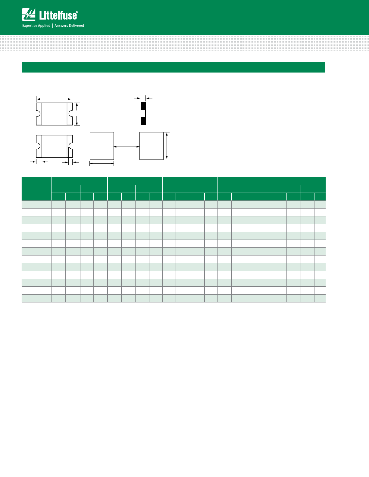
Dimensions
Bo
MARKING CODE VARIES
WITH AMPERAGE RATING
(See Electrical Characteristics Table)
SHOWN IS 1.5AMP RATING
A
POLY-FUSE® Resettable PTCs
Surface Mount > 1210L Series
C
Top
View
ttom
View
K
K
D
B
Pad
Layout
E
1. 00 mm
(.040)
2.00 mm
(.079)
Side
View
2.50 mm
(.098)
A B C D E
Part
Number
Inches mm Inches mm Inches mm Inches mm Inches mm
Min Max Min Max Min Max Min Max Min Max Min Max Min Max Min Max Min Max Min Max
1210L005 0.12 0.14 3.0 3.43 0.09 0.11 2.35 2.80 0.03 0.05 0.75 1.25 0.01 0.03 0.25 0.75 0.004 0.02 0.1 0.5
1210L010 0.12 0.14 3.0 3.43 0.09 0.11 2.35 2.80 0.03 0.05 0.75 1.25 0.01 0.03 0.25 0.75 0.004 0.02 0.1 0.5
1210L020 0.12 0.14 3.0 3.43 0.09 0.11 2.35 2.80 0.02 0.04 0.60 1. 0 0 0.01 0.03 0.25 0.75 0.004 0.02 0.1 0.5
1210L035 0.12 0.14 3.0 3.43 0.09 0.11 2.35 2.80 0.02 0.03 0.50 0.85 0.01 0.03 0.25 0.75 0.004 0.02 0.1 0.5
1210L050 0.12 0.14 3.0 3.43 0.09 0.11 2.35 2.80 0.02 0.03 0.50 0.85 0.01 0.03 0.25 0.75 0.004 0.02 0.1 0.5
1210L075 0.12 0.14 3.0 3.43 0.09 0.11 2.35 2.80 0.02 0.03 0.50 0.85 0.01 0.03 0.25 0.75 0.004 0.02 0.1 0.5
1210L075/24 0.12 0.14 3.0 3.43 0.09 0.11 2.35 2.80 0.05 0.07 1.20 1.80 0.01 0.03 0.25 0.75 0.004 0.02 0.1 0.5
1210L110/12 0.12 0.14 3.00 3.43 0.09 0.11 2.35 2.80 0.03 0.05 0.75 1.25 0.010 0.030 0.25 0.75 0.004 0.020 0.10 0.50
1210L110/16 0.12 0.14 3.00 3.43 0.09 0.11 2.35 2.80 0.03 0.05 0.75 1.25 0.010 0.030 0.25 0.75 0.004 0.020 0.10 0.50
1210L110TH 0.12 0.14 3.0 3.43 0.09 0.11 2.35 2.80 0.04 0.05 0.30 0.71 0.01 0.03 0.25 0.75 0.004 0.02 0.1 0.5
1210L150TH 0.12 0.14 3.0 3.43 0.09 0.11 2.35 2.80 0.03 0.07 0.75 1.07 0.01 0.03 0.25 0.75 0.004 0.02 0.1 0.5
1210L175 0.12 0.14 3.0 3.43 0.09 0.11 2.35 2.80 0.02 0.04 0.60 1. 0 0 0.01 0.03 0.25 0.75 0.004 0.02 0.1 0.5
1210L200 0.12 0.14 3.0 3.43 0.09 0.11 2.35 2.80 0.03 0.06 0.80 1.60 0.01 0.03 0.25 0.75 0.004 0.02 0.1 0.5
Specifications are subject to change without notice.
© 2013 Littelfuse, Inc.
Revised: 11/05/13
Page 5

POLY-FUSE® Resettable PTCs
=2,000
Surface Mount > 1210L Series
Part Ordering Number System
1210 L 380 /12 TH Y R
PACKAGING STYLE
R: Tape & Reel
SERIES
SIZE
HOLD CURRENT CODE
I
HOLD
(Refer to Electrical Characteristics Table)
L: LITTELFUSE SURFACE MOUNT PPTC
QUANTITY CODE: K=10,000 Y=4,000 W=3,000 P
THIN PROFILE
(Not applicable to all parts)
/XX: SPECIAL VOLTAGE RATING
(Not applicable to all parts. Refer
to Electrical Characteristics Table)
Packaging Options
Part Number
Ordering
Number
Halogen Free I
hold
(A)
I
hold
Code
Packaging Option Quantity
1210L005 1210L005WR Ye s 0.05 005 Tape and Reel 3000 WR
1210L010 1210L010WR Ye s 0.10 010 Tape and Reel 3000 WR
1210L020 1210L020WR Ye s 0.20 020 Tape and Reel 3000 WR
1210L035 1210L035YR Ye s 0.35 035 Tape and Reel 4000 YR
1210L050 1210L050YR Ye s 0.50 050 Tape and Reel 4000 YR
1210L075 1210L075YR Ye s 0.75 075 Tape and Reel 4000 YR
1210L075/24 1210L075/24PR Ye s 0.75 075 Tape and Reel 2000 PR
1210L110/12 1210L110/12WR Ye s 1. 10 110 Tape and Reel 3,000 WR
1210L110/16 1210L110/16WR Ye s 1. 10 110 Tape and Reel 3,000 WR
1210L110TH 1210L110THYR Ye s 1. 10 110 Tape and Reel 4000 YR
1210L150TH 1210L150THWR Ye s 1.50 150 Tape and Reel 3000 WR
1210L175 1210L175WR Ye s 1.75 175 Tape and Reel 3000 WR
1210L200 1210L200PR Ye s 2.00 200 Tape and Reel 2000 PR
Quantity & Packaging
Codes
1210L Series
© 2013 Littelfuse, Inc.
Specifications are subject to change without notice.
Revised: 11/05/13
Page 6

POLY-FUSE® Resettable PTCs
Surface Mount > 1210L Series
Tape and Reel Specifications
TAPE SPECIFICATIONS: EIA-481-1 (mm)
Packaging Code “YR”:
1210L035
1210L050
1210L075
1210L110TH
W
F
E
1
D
0
D
1
P
0
P
1
P
2
A
0
B
0
T
K
0
8.0+/- 0.30 8.0+/- 0.30 8.0+/- 0.30 H 12.0+/- 0.05
3.5+/- 0.05 3.5+/- 0.05 3.5+/- 0.05 W 9.0+/- 0.5
1.75+/- 0.10 1.75+/- 0.10 1.75+/- 0.10 D Ø 60+0.5
1.55+/- 0.05 1.55+/- 0.05 1.55+/- 0.05 F Ø 13.0+/- 0.2
1.0 (min) 1.0 (min) 1.0 (min) C Ø 178+/- 1.0
4.0+/- 0.10 4.0+/- 0.10 4.0+/- 0.10 H
4.0+/- 0.10 4.0+/- 0.10 4.0+/- 0.10 W
2.0+/- 0.05 2.0+/- 0.05 2.0+/- 0.05 W
2.82+/- 0.10 2.82+/- 0.10 2.67+/- 0.10 W
3.46+/- 0.10 3.46+/- 0.10 3.36+/- 0.10 W
0.25+/- 0.10 0.25+/- 0.10 0.25+/- 0.10
1.00+/- 0.10 1.30+/- 0.10 1.65+/- 0.10
Leader min. 390 390 390
Trailer min. 160 160 160
P
1
Packaging Code “WR”:
1210L005
1210L 010
1210L020
1210L110/12
1210L110/16
1210L150TH
1210L175
D
P
0
Packaging Code “PR”:
1210L075/24
1210L200
P
0
2
E
REEL DIMENSIONS:
EIA-481-1 (mm)
11+/- 0.5
1
2.2+/- 0.5
1
3.0+0.5
2
4.0+0.5
3
5.5+0.5
4
H
1
W
4
W
3
D
F
W
T
A
0
D
2
K
0
B
0
W
2
F
W
1
H
1
Specifications are subject to change without notice.
© 2013 Littelfuse, Inc.
C
W
Revised: 11/05/13
 Loading...