

Littelfuse FHZ Series, 0FHZ0001Z, 0FHZ0005Z, 0FHZ0002Z Installation Instructions Manual
Installation Instructions
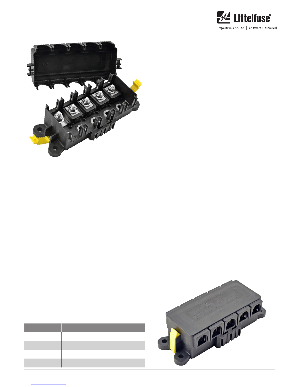
FHZ Series 5-Stud ZCASE® Fuse Holder
Part Numbers: 0FHZ0001Z, 0FHZ0002Z & 0FHZ0005Z
Installation
Assemble the fuse holder in the following sequence:
1. Open AssureLatches and remove cover. If you are using
the 0FHZ0002Z, remove the nuts and the green rubber
dust covers.
2. Place the ZCASE fuses on the studs to match stud size
and loads. If you are using the optional dust covers
replace them in the slots all the way down allowing the
tabs to engage the fuse bodies.
• Remember when selecting fuse values the continuous
current through a fuse should be calculated as 75%
of the rated value of the fuse (200A fuse should carry
150A max continuous current).
• The total long term continuous current for all fuses
should not exceed 400A.
• Intermittent loads such as motor start, starter or
compressor should not exceed 600A for 20 seconds.
3. Place ZCASE fuse holder into the mounting position
and mark the location on the mounting surface for the
mounting bolts. Drill four holes to accommodate the M8
Mounting hardware. Bolt the holder to the mounting
Description
The 5-Stud ZCASE Fuse Holder is a configurable product
designed to do primary high current power distribution. It
uses a power input terminal usually paired with a ZCASE
shunt for the input. With a common bussed power,
configurable studs (choose M6, M8, or M10) and appropriate
ZCASE fuses a wide variety of configurations is possible. The
dust covers keep dust out of the backside of the fuse box and
the cover protects the fuses from debris.
Specifications Overview
Amperage: 400A Continuous
Available Fuse Rating: 40- 600A
Accessories: Studs, Bus Bar, Tether, Dust Cover
Box Dimensions: 217mm x 96mm x 59mm
Contact Temp: -40° to 105° C
Connections: M6, M8, and M10 Bolt
Down Connection
Color: Black
surface with four M8 bolts torqued to XXNm maximum
4. Place an appropriate sized output cable with an a terminal
matched to the stud size on the top of the ZCASE
fuses and put on an appropriate nuts on the isolated
studs. Torque the nuts to 14Nm±2Nm for M8 studs and
16Nm±2Nm for M10 studs. Be sure to hold the wire and
terminal while applying torque to prevent twisting which
can damage the fuse element.
5. Be sure that the output cables are routed so they
have sufficient bend radius and are not at risk of being
damaged or pinched. Lastly, make sure that all cables
are strain relieved by being supported within 18” of the
battery.
6. Replace the cover and snap the AssureLatch latches
into place Note: the cover is designed to take a label, so
good practice is to label the fuse box so each fuse and its
loads are identified, as this makes troubleshooting later
much easier
Step by step images shown in Figure 2 on page 2.
Figure 1 - Covered Assembly
Web Resources
Download 2D print and technical resources at:
littelfuse.com/5studzcase
Ordering Information
PART NUMBERS DESCRIPTION
0FHZ0001Z 5-Stud Assembly with Bolts and Bus Bar
0FHZ0002Z 5-Stud Full Assembly with M10 Input
0FHZ0003Z 5-Stud Box Only for Configuration
0FHZ0005Z 5-Stud Full Assembly with M8 Input
littelfuse.com
1 of 2
Rev: 082018© 2018 Littelfuse Commercial Vehicle Products
Installation Instructions
FHZ Series 5-Stud ZCASE® Fuse Holder
Part Numbers: 0FHZ0001Z, 0FHZ0002Z & 0FHZ0005Z
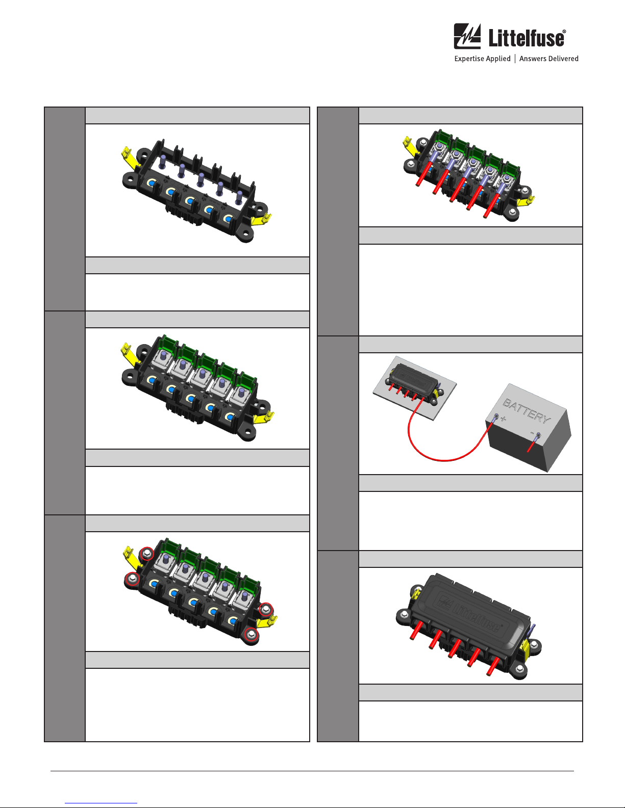
Figure 2 - Step by Step Installation
STEP
1
STEP
2
IMAGE
DETAILS
Open AssureLatches and remove cover. If you are
using the 0FHZ0002Z, remove the nuts and the
green rubber dust covers.
IMAGE
DETAILS
Place the ZCASE fuses on the studs to match stud
size and loads. If you are using the optional dust
covers replace them in the slots all the way down
allowing the the tabs to engage the fuse bodies.
IMAGE
STEP
4
STEP
5
IMAGE
DETAILS
Place an appropriate sized output cable with an a
terminal matched to the stud size on the top of the
ZCASE fuses and lput on an appropriate nuts on
the isolated studs. Torque the nuts to 14Nm±2Nm
for M8 studs and 16Nm±2Nm for M10 studs. Be
sure to hold the wire and terminal while applying
torque to prevent twisting which can damage the
fuse element.
IMAGE
DETAILS
Be sure that the output cables are routed so they
have sufficient bend radius and are not at risk of
being damaged or pinched. Lastly, make sure that
all cables are strain relieved by being supported
within 18” of the battery.
IMAGE
STEP
3
DETAILS
Place ZCASE fuse holder into the mounting
position and mark the location on the mounting
surface for the mounting bolts. Drill four holes to
accomodate the M8 Mounting hardware. Bolt the
holder to the mounting surface with four M8 bolts
torqued to XXNm maximum.
Specifications, descriptions and illustrative material in this literature are as accurate as known at the time of publication,
but are subject to changes without notice. Visit littelfuse.com for the most up-to-date technical information.
littelfuse.com
2 of 2
STEP
6
DETAILS
Replace the cover and snap the AssureLatch
latches into place. Apply a label to the cover to
designate the fuses and their loads.
Rev: 082018© 2018 Littelfuse Commercial Vehicle Products
 Loading...