

Page 1
READ AND FOLLOW ALL SAFETY INSTRUCTIONS!
SAVE THESE INSTRUCTIONS AND DELIVER TO OWNER AFTER INSTALLATION
· To reduce the risk of death, personal injury or property damage from re, electric shock, falling parts, cuts/
abrasions, and other hazards please read all warnings and instructions included with and on the xture box and
all xture labels.
· Before installing, servicing, or performing routine maintenance upon this equipment, follow these general
precautions.
· Installation and service of luminaires should be performed by a qualied licensed electrician.
· Maintenance of the luminaires should be performed by person(s) familiar with the luminaires’ construction and
operation and any hazards involved. Regular xture maintenance programs are recommended.
· It will occasionally be necessary to clean the outside of the refractor/lens. Frequency of cleaning will depend on
ambient dirt level and minimum light output which is acceptable to user. Refractor/lens should be washed in a
solution of warm water and any mild, non-abrasive household detergent, rinsed with clean water and wiped dry.
Should optical assembly become dirty on the inside, wipe refractor/lens and clean in above manner, replacing
damaged gaskets as necessary.
· DO NOT INSTALL DAMAGED PRODUCT! This luminaire has been properly packed so that no parts should have
been damaged during transit. Inspect to conrm. Any part damaged or broken during or after assembly should
be replaced.
· Recycle: For information on how to recycle LED electronic products, please visit www.epa.gov.
· These instructions do not purport to cover all details or variations in equipment nor to provide every possible
contingency to meet in connection with installation, operation, or maintenance. Should further information
be desired or should particular problems arise which are not covered suciently for the purchaser’s or owner’s
purposes, this matter should be referred to Acuity Brands Lighting, Inc.
WARNING
RISK OF ELECTRIC SHOCK
Disconnect or turn o power before installation or
servicing.
Verify that supply voltage is correct by comparing it with
the luminaire label information.
Make all electrical and grounded connections in
accordance with the National Electrical Code (NEC) and
any applicable local code requirements.
All wiring connections should be capped with UL
approved recognized wire connectors.
CAUTION
RISK OF INJURY
Wear gloves and safety glasses at all times when
removing luminaire from carton, installing, servicing or
performing maintenance.
Avoid direct eye exposure to the light source while it is on.
WARNING
RISK OF BURN
Allow lamp/xture to cool before handling. Do not
touch enclosure or light source.
Do not exceed maximum wattage marked on
luminaire label.
Follow all manufacturer’s warnings, recommendations
and restrictions for: driver type, burning position,
mounting locations/methods, replacement and
recycling.
CAUTION
RISK OF FIRE
Keep combustible and other materials that can burn,
away from lamp/lens.
Do not operate in close proximity to persons,
combustible materials or substances aected by heat
or drying.
Page 2
CAUTION: RISK OF PRODUCT DAMAGE
Never connect components under load.
Do not mount or support these xtures in a manner that can cut the outer jacket or damage wire
insulaon.
Controls for dimming, auto-sensing, or remote control of a luminaire that are not factory-wired to the
luminaire must be checked for compability with the luminaire prior to installaon. LED xtures must
be powered directly o a switched circuit.
Unless individual product specicaons deem otherwise: Do not restrict xture venlaon. Allow for
some volume of airspace around xture. Avoid covering LED xtures with insulaon, foam, or other
material that will prevent convecon or conducon cooling.
Unless individual product specicaons deem otherwise: Do not exceed xtures maximum ambient
temperature.
Only use xture in its intended locaon.
LED products are Polarity Sensive. Ensure proper Polarity before installaon.
Electrostac Discharge (ESD): ESD can damage LED xtures. Personal grounding equipment must be
worn during all installaon or servicing of the unit.
Do not touch individual electrical components as this can cause ESD, shorten lamp life, or alter
performance.
Some components inside the xture may not be serviceable. In the unlikely event your unit may
require service, stop using the unit immediately and contact an ABL representave for assistance.
Always read the xtures complete installaon instrucons prior to installaon for any addional xture
specic warnings.
Please see product specific installation instructions for additional warnings or any applicable FCC or other regulatory statements.
Failure to follow any of these instructions could void product warranties. For a complete listing of product Terms and Conditions, please visit www.acuitybrands.com.
Our Brands Indoor/Outdoor Indoor Lighting Outdoor Lighting Controls Daylighting
Lithonia Lighting Gotham American Electric Lighting DARK TO LIGHT SunOptics
Carandini Mark Architectural Lighting Antique Street Lamps LC&D
Holophane Peerless Hydrel ROAM
RELOC Renaissance Lighng Tersen Sensor Switch
Light Concepts Winona Lighting Synergy
Acuity Brands Lighting, Inc. assumes no responsibility for claims arising out of improper or careless installation or handling of its products.
ABL LED General Warnings, Form No. 503.203
© 2010 Acuity Brands Lighting, Inc. All rights reserved. 12/01/10
Page 3

Installation Instructions
RSX LED
5 year limited warranty
DELIVERY: Upon receipt of xture and accessories (packed separately), thoroughly inspect for any freight damage. All damage should
be reported to the delivery carrier. Compare the catalog description listed on the packing slip with the xture label on the inside of
the housing to be sure you have received the correct merchandise.
is device complies with Part 15 of the FCC Rules. Operation is
subject to the following two conditions: (1) this device may not cause
harmful interference, and (2) this device must accept any interference
received, including interference that may cause undesired operation.
Figure 1
RSX SPA/RPA INSTALLATION INSTRUCTION
Tools Required: Socket wrenches: 3/8"; Allen wrench: 5/32"
Minimum square pole: 3.5" face
Minimum round pole: 3.2" diameter
1. Loosen two captive screws on cover of the SPA to access the
pole mounting area (See Figure 1).
2. Two mounting bars are included in the installation kit:
a. e shorter bar is used for #8 Lithonia drilling and has 3
holes. e top and bottom hole are threaded.
b. e longer bar has 1 top hole and a slot with a
sliding threaded hole to be used on poles with existing drill
patterns.
3. Hold the rst bar (See Figure 2a) with 3 holes
up to the mounting holes on the pole and if they
align use that bar. Use the bar (See Figure 2b) with
the sliding thread for all other patterns.
Figure 2a Figure 2b Figure 2c
Top Hole
Insert one 3/8 mounting bolt through the top
hole of the pole. read this bolt into the at bar
(See Figure 2a) stock top hole. If the pole has a
dierent hole pattern, use the bar (See Figure
2b) with the slide on it. For a round pole, the
round pole adapter (RPA) is required which is
placed between the pole and the xture as shown
with curved side contacting pole and at side facing
away from pole (See Figure 2c).
Lithonia Lighting Outdoor
©2016 Acuity Brands Lighting, Inc.
All Rights Reserved.
One Lithonia Way, Conyers, GA 30012
Phone: 800-279-8041 Fax: 770-918-1209
www.lithonia.com
Part Number: IN-379 Rev F
Revision Date: 11/19/18
Page 4
Installation Instructions
First Bolt
Key Hole Slot
location
Second Bolt
SPA Cover
Mounting
Bolts
RSX LED
4. e luminaire is supplied with a variety of slots to
align with existing pole mounting drill patterns. e top
hole of the luminaire arm has a key hole slot.
Place the luminaire onto the top bolt by passing the head
through the key slot and resting the luminaire down securely
in place (See Figure 3).
WARNING: THE LUMINAIRE IS NOT COMPLETELY
LOCKED DOWN YET. SPECIAL CARE MUST BE TAKEN
TO AVOID JARRING THE LUMINAIRE FROM ITS REST
ING POINT, OTHERWISE THE LUMINAIRE COULD
FALL AND CAUSE SERIOUS INJURY OR DEATH!
Ensure the luminaire is resting securely on the top bolt. Snug
the bolt but do not completely tighten. read the second
bolt through the arm slot and into the available threaded hole
of the mounting bar (See Figure 4).
Figure 3
5. e luminaire is supplied with a clearance slot in the
back to allow wires to be pulled into the pole on existing hole
patterns. Insert the wires through the clearance slot shown in
Figure 5 and pull them into the pole.
6. Ensure luminaire is straight/level making sure that no wires
are pinched, tighten the two bolts with a 3/8 socket to 20-30
-lbs (overtightening can damage components and void warranties). Make sure that wires are not pinched and tuck excess
wire up into the luminaire mounting area.
7. Reinstall the SPA Cover that was removed, tighten the two
captive screws with the 9/64 Allen wrench to 18-20 in-lbs
(overtighten can cause thread stripping and void all warranties)(See Figure 6).
8. Make wire connections in the pole, observing proper voltage and polarity. Connect green ground wire from the xture
to the eld ground wire. Secure wires; push back into pole
and replace pole cap.
Figure 4
Figure 5
Figure 6
©2016 Acuity Brands Lighting, Inc.
All Rights Reserved.
Lithonia Lighting Outdoor
One Lithonia Way, Conyers, GA 30012
Phone: 800-279-8041 Fax: 770-918-1209
www.lithonia.com
Part Number: IN-379 Rev F
Revision Date: 11/19/18
Page 5
Installation Instructions
Thru Bolt Hole
RSX LED
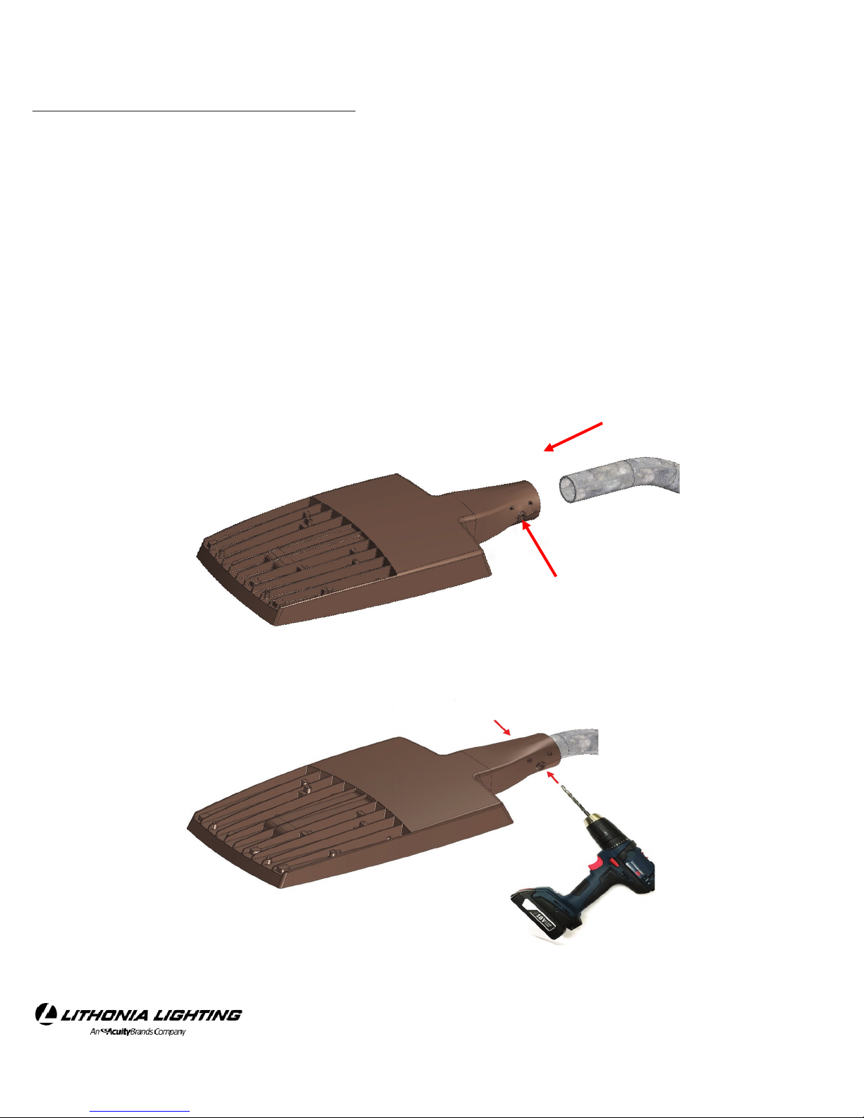
RSX MAST ARM ADAPTOR INSTALLATION
Tools Required: Socket wrenches: 5/8"; Allen wrench: 5/16"
Minimum tenon/pole diameter: 2" schedule 40 pipe (2-3/8" OD)
1. Slip luminaire Mast Arm Mount over 2-3/8ӯ pole tenon (See Figure 7a).
2. Use provided set screws and secure the luminaire in required position.
3. Use thru-bolt hole provided as pilot and drill 1/2" Ø hole on tenon
through mast arm from both side (See Figure 7b).
Figure 7a
©2016 Acuity Brands Lighting, Inc.
All Rights Reserved.
Figure 7b
Lithonia Lighting Outdoor
One Lithonia Way, Conyers, GA 30012
Phone: 800-279-8041 Fax: 770-918-1209
www.lithonia.com
Part Number: IN-379 Rev F
Revision Date: 11/19/18
Page 6

Installation Instructions
RSX LED
3. Loosen six captive screws on RSX luminaire door to access the wire connection area.
Remove the rubber grommet before feeding the wires (See Figure 8a).
Figure 8a
Remove the Rubber
Grommet
4. Insert the wires through the holes of the rubber grommet, pull them into the wire connection area.
Replace the rubber grommet back as originally assembled before wire feeding (See Figure 8b & 8c).
Figure 8b Figure 8c
©2016 Acuity Brands Lighting, Inc.
All Rights Reserved.
Lithonia Lighting Outdoor
One Lithonia Way, Conyers, GA 30012
Phone: 800-279-8041 Fax: 770-918-1209
www.lithonia.com
Part Number: IN-379 Rev F
Revision Date: 11/19/18
Page 7

Installation Instructions
RSX LED
5. Insert the ground wire comes from tenon to the 3 way Wago connector with the green wires from SPD and luminaire ground connection and lock it. Repeat this step for black (hot) and white (neutral) wires. Select Wago connectors with matching colored wires coming from SPD (See Figure 9a, 9b, 9c).
Figure 9bFigure 9a Figure 9c
6. Use cable tie and tie all newly attached wires shown in
Figure 10.
7. Make sure that wires are not pinched, the door gasket did not move from original position, and sits in its
groove on the door properly. Reinstall the mounting
door (Figure 11) that was removed, tighten the six captive screws with the 5/32 Allen wrench to 25-30 in-lbs
(overtighten can cause thread stripping and void all
warranties).
Figure 10
©2016 Acuity Brands Lighting, Inc.
All Rights Reserved.
Figure 11
Lithonia Lighting Outdoor
One Lithonia Way, Conyers, GA 30012
Phone: 800-279-8041 Fax: 770-918-1209
www.lithonia.com
Part Number: IN-379 Rev F
Revision Date: 11/19/18
Page 8

Installation Instructions
RSX LED
RSX MAST ARM ADAPTOR INSTALLATION
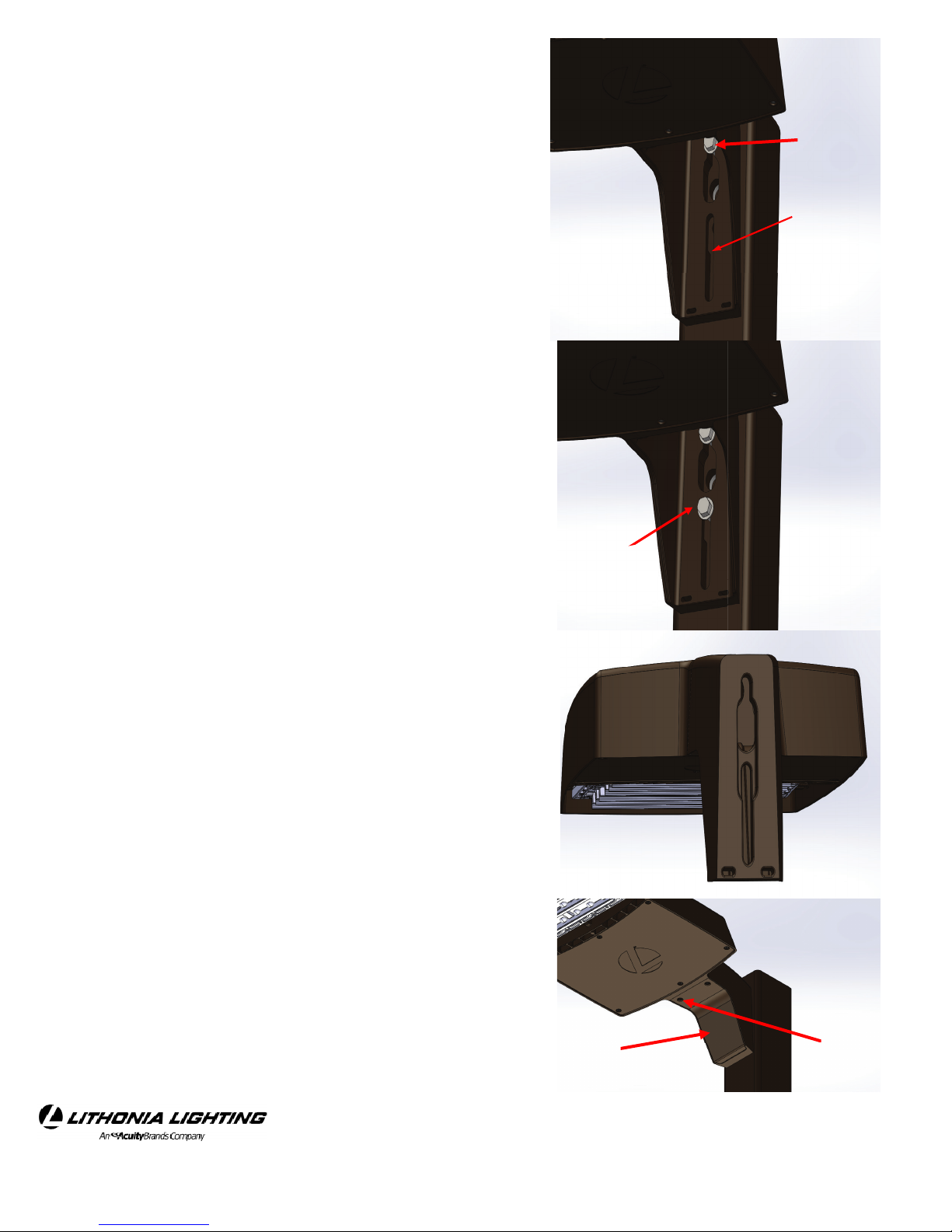
Figure 11a
8. Reorient luminaire to desired position on the tenon
(See Figure 11a & 11b).
9. Insert provided 7/16"-14 x 4-1/2" bolt through
Mast Arm Mount and drilled 1/2" Ø hole on tenon
and place provided 7/16" nut onto bolt and tighten
securely to 45-50 -lbs.
10. Evenly tighten the Six (6) 3/8-16 UNC
Mast Arm Set Bolts while maintaining the correct
position of the luminaire to 23-27 -lbs.
11. Energize the luminaire to verify its operation
and proper illumination of area.
WARNING: USE AND PROPERLY TIGHTEN
THRU-BOLT AND NUT. FAILURE TO CORRECTLY INSTALL COULD RESULT IN SERIOUS INJURY
OR DEATH.
Pole Tenon
Set Bolts
7/16-14 Bolt
ru Bolt
Hole
Figure 11b
©2016 Acuity Brands Lighting, Inc.
All Rights Reserved.
Lithonia Lighting Outdoor
One Lithonia Way, Conyers, GA 30012
Phone: 800-279-8041 Fax: 770-918-1209
www.lithonia.com
Part Number: IN-379 Rev F
Revision Date: 11/19/18
Page 9

Installation Instructions
RSX LED
RSX INTEGRAL SLIPFITTER (KNUCKLE) INSTALLATION ON VERTICAL TENONS (+/- 5 °)
Note: Luminaire can be tilted up to 90 degrees (maximum) above horizontal.
Tools Required:
Allen wrench: 9/64”, 5/16“, 3/8”
Maximum tenon/pole diameter: 2” schedule 40 pipe (2-3/8” OD)
is luminaire is pre-wired with UL listed supply wire leads. It is not necessary to access xture housing to install or
wire the luminaire.
1. Remove the two (2) 8-32 splice access cover fasteners from knuckle assembly, remove the splice access cover, and
pull supply wire leads from knuckle cavity (See Figure 12a)
2. Slip luminaire knuckle tter over 2-3/8ӯ pole tenon and evenly tighten the six (6) 3/8-16 UNC knuckle tenon set
screws to 23-27 -lbs, while maintaining the correct position of the luminaire.
3. Cut and splice the wires. Recommended cut length is 6" for wires for ease of splicing and securing in the knuckle.
(See Figure 12b)
4. Make all wiring connections via the supplied wire leads in accordance with NEC and local codes.
5. Push all xture and supply wires completely within the knuckle cavity and replace the splice access cover, gasket,
and two (2) 8-32 splice access cover fasteners.
Figure 12a
Figure 12b
Splice Access
Cover Bolts
Splice Access
Cover
Knuckle Tenon
Set Bolts
Pole Tenon
©2016 Acuity Brands Lighting, Inc.
All Rights Reserved.
Lithonia Lighting Outdoor
One Lithonia Way, Conyers, GA 30012
Phone: 800-279-8041 Fax: 770-918-1209
www.lithonia.com
Part Number: IN-379 Rev F
Revision Date: 11/19/18
Page 10

Installation Instructions
RSX LED
6. Aim xture as required and tighten the 7/16-14 SHC knuckle adjustment bolt using an approximately 38 -lbs.(See
Figure 12c)
7. For units with photocontrol receptacle, the xture mounting/aiming angle must be restricted from 0° to 45° from
horizontal per ANSI C136.10-2010.
8. Energize the luminaire to verify its operation and proper illumination of area.
WARNING: DO NOT MOUNT THE KNUCKLE FITTER TO A TENON OR BRACKET THAT IS MORE THAN 5
DEGREES FROM VERTICAL. MOUNTING AT AN ANGLE GREATER THAN 5 DEGREES REQUIRES USE OF A
PROPERLY TIGHTENED THRU-BOLT AND LOCKNUT. FAILURE TO CORRECTLY INSTALL COULD RESULT
IN SERIOUS INJURY OR DEATH.
Figure 12c
Knuckle adjustment bolt
©2016 Acuity Brands Lighting, Inc.
All Rights Reserved.
Lithonia Lighting Outdoor
One Lithonia Way, Conyers, GA 30012
Phone: 800-279-8041 Fax: 770-918-1209
www.lithonia.com
Part Number: IN-379 Rev F
Revision Date: 11/19/18
Page 11

Installation Instructions
7/16-14 x 3 -3/4”
Bolt
7/16-14
Locknut
RSX LED
RSX INTEGRAL SLIPFITTER (KNUCKLE) INSTALLATION ON TENONS W/ANGLES >5 ° FROM VERTICAL
Note: Luminaire can be tilted up to 90 degrees (maximum) above horizontal.
Tools Required:
1/2” Ø Drill bit, 5/8“ Socket wrench
Grade 5 Steel, 7/16-14 x 3-3/4” High corrosion rated
bolt, Grade 5 Steel, 7/16-14 Center-Lock, Distortedread high corrosion rated Locknut.
Allen wrench: 9/64”, 5/16“, 3/8”
Maximum tenon/pole diameter: 2” schedule 40 pipe
(2-3/8” OD)
is luminaire is pre-wired with UL listed supply wire
leads. It is not necessary to access xture housing to
install or wire the luminaire.
Figure 13a
1. Slip luminaire knuckle tter over 2-3/8” Ø pole
tenon and remove upper set screw at the front face of
the knuckle. Evenly tighten the ve (5) 3/8-16 UNC
knuckle tenon set screws to 23-27 -lbs, while maintaining the correct position of the luminaire.
2. Use upper set screw hole on front face of the knuckle
as pilot and drill 1/2" Ø hole on tenon through knuckle (See Figure 13a)
3. Insert 7/16"-14 x 3-3/4" bolt through Knuckle and
drilled 1/2" Ø hole on tenon. Place 7/16" Center-Lock
Distorted-read Locknut onto bolt and tighten securely to 45-50 -lbs. (See Figure 13b)
4. Retighten the ve (5) 3/8-16 UNC Knuckle set bolts
to 23-27 -lbs.
Figure 13b
©2016 Acuity Brands Lighting, Inc.
All Rights Reserved.
Lithonia Lighting Outdoor
One Lithonia Way, Conyers, GA 30012
Phone: 800-279-8041 Fax: 770-918-1209
www.lithonia.com
Part Number: IN-379 Rev F
Revision Date: 11/19/18
Page 12

Installation Instructions
Cover
Gasket
Remove Tilt
limiting screw
Splice access
cover fasteners
Tilt
limiting screw
Knuckle adjustment
Bolt
RSX LED
5. Loose the two (2) 8-32 splice access cover fasteners from knuckle assembly, remove the splice access
cover, and pull supply wire leads from knuckle cavity.
6. Remove tilt limiting screw if necessary (See Figure 13c, 13d). Note: Luminaire can be tilted up to 90
degrees (maximum) above horizontal.
7. Make all wiring connections via the supplied wire
leads in accordance with NEC and local codes.
8. Push all xture and supply wires completely within
the knuckle cavity. Ensure the splice box gasket is in
place and replace the splice access cover. Tighten the
two captive screws with the 9/64 Allen wrench to 1820 in-lbs (overtighten can cause thread stripping and
void all warranties) (See Figure 13c & 13d).
9. Aim xture as required and tighten the 7/16-14
SHC knuckle adjustment bolt using an approximately
38 -lbs. (See Figure 13e)
Figure 13c
10. For units with photocontrol receptacle, the xture
mounting/aiming angle must be restricted to ± 45°
from horizontal per ANSI C136.10-2010.
11. Energize the luminaire to verify its operation and
proper illumination of area.
Figure 13d
WARNING: DO NOT MOUNT THE KNUCKLE FITTER TO A TENON BELOW HORIZONTAL EVEN
WITH PROPERLY TIGHTEN THRU-BOLT AND
LOCKNUT. FAILURE TO CORRECTLY INSTALL
COULD RESULT IN SERIOUS INJURY OR DEATH.
Figure 13e
©2016 Acuity Brands Lighting, Inc.
All Rights Reserved.
Lithonia Lighting Outdoor
One Lithonia Way, Conyers, GA 30012
Phone: 800-279-8041 Fax: 770-918-1209
www.lithonia.com
Part Number: IN-379 Rev F
Revision Date: 11/19/18
Page 13

Installation Instructions
Base Plate
(4 ) ¼” Fasteners
(by others)
Curved portion
of the cover plate
Factory installed
gasket
RSX LED
RSX WBA INSTALLATION
Tools Required: Socket wrenches: 9/16"; Allen wrench: 9/64"
1. CAUTION: APPLY A CONTINUOUS BEAD OF WEATHER – PROOF CAULKING BETWEEN MOUNTING
BASE PLATE AND WALL TO ENSURE WEATHER – TIGHT INTEGRITY OF ELECTRICAL COMPONENTS (See
Figure 14a & 14b ).
2. Place the base plate in orientation shown in Figure 14a and secure to wall with secure base plate to wall with (4)
1/4” diameter fasteners (by others) using the (4) holes located on the outer corners of the base plate. Check the base
plate to conrm that it is level and plumb in all directions (See Figure 14b).
3. Prepare the cover plate by ensuring the factory installed gasket is in place on the backside of the cover plate (See
Figure 15).
4. Open up the light xture carton and locate the threaded steel bar, and the (2) 3/8” diameter lock bolts that are
2-1/2” long.
5. Note for the next steps the curved portion of the cover plate should point upwards when mounted to the wall (See
Figure 15).
Figure 14a Figure 14b
©2016 Acuity Brands Lighting, Inc.
All Rights Reserved.
Figure 15
Lithonia Lighting Outdoor
One Lithonia Way, Conyers, GA 30012
Phone: 800-279-8041 Fax: 770-918-1209
www.lithonia.com
Part Number: IN-379 Rev F
Revision Date: 11/19/18
Page 14

Installation Instructions
Threaded
steel bar
Clearance slot
3/8” diameter lock
bolts
SPA Cover c aptive
sc r e ws
SPA Cover
RSX LED
6. Loosen two captive screws on cover of the SPA to access the pole mounting area.(See Figure 16)
7. e luminaire is supplied with a clearance slot in the back to allow wires to be pulled into the WBA cover
plate on existing hole.
8. Making sure that no wires are pinched, insert the 3/8” lock bolts through the back wall of the xture housing,
through the cover plate, and then thread into the threaded steel bar (See Figure 17). Tighten the two bolts with a 9/16
socket to 20-30 -lbs (overtightening can damage components and void warranties). Make sure that wires are not
pinched and tuck excess wire up into the luminaire mounting area.
9. Reinstall the SPA Cover that was removed in step 6, tighten the two captive screws with the 9/64 Allen wrench to
18-20 in-lbs (overtighten can cause thread stripping and void all warranties).
Figure 16
Figure 17
CAUTION THE NEXT STEPS WILL REQUIRE ASSISTANCE:
10. Make all wiring connections via the supplied wire leads in accordance with NEC and local codes.
11. Place the entire light xture/cover plate assembly onto the base plate (Figure 14b)and have someone tighten the
top (2) 3/8” x 1-1/4” stainless steel recessed hex set screws (See Figure 18) until 3/8” to 1/4” of the screw threads are
still visible, then the bottom set screws.
12. Now alternating between the top two and bottom two set screws, gently tighten until snug (approximately one
thread will remain showing on each screw)
Figure 14b
©2016 Acuity Brands Lighting, Inc.
All Rights Reserved.
3/8" x 1-1/4
recessed hex
set screws (4)
Lithonia Lighting Outdoor
One Lithonia Way, Conyers, GA 30012
Phone: 800-279-8041 Fax: 770-918-1209
www.lithonia.com
Figure 18
Part Number: IN-379 Rev F
Revision Date: 11/19/18
Page 15

Installation Instructions
FAO
Adjustment
Dial
RSX LED
RSX FAO SETTING INSTRUCTIONS
1. Loosen six captive screws and remove RSX door to access the FAO setting area (gure 19). Set aside for reinstallation.
Figure 19
2. Use at screw driver to turn FAO dial to get required Lumen output. (See Figure 20)
See table for settings. (Table 1)
Figure 20
©2016 Acuity Brands Lighting, Inc.
All Rights Reserved.
Lithonia Lighting Outdoor
One Lithonia Way, Conyers, GA 30012
Phone: 800-279-8041 Fax: 770-918-1209
www.lithonia.com
Part Number: IN-379 Rev F
Revision Date: 11/19/18
Page 16

Installation Instructions
RSX LED
RSX FAO SETTING INSTRUCTIONS
FAO - Field Adjustable Output Settings
Fixture Size FAO Position Input watts (W) *Lumens (approx.)
RSX1 LED P4
RSX2 LED P6
Table 1
1 22 3,721
2 38 5,990
3 54 8,115
4 70 10,103
5 88 11,961
6 105 13,672
7 124 15,251
8 133 16,000
1 41 6,966
2 70 11,161
3 99 15,122
4 130 18,844
5 161 22,326
6 194 25,566
7 227 28,563
8 244 30,000
1 55 9,002
2 91 14,368
3 129 19,518
RSX3 LED P4
4 167 24,448
5 207 29,158
6 248 33,644
7 290 37,908
8 312 40,000
*Values are based on the highest performance package for each xture size
*FAO device shipped set at maximum setting #8
*Lumen values vary by optic type
3. Make sure that wires are not pinched, the door gasket did not move from original position, and sits in its groove
on door properly, reinstall the door, tighten the six captive screws with the 5/32 Allen wrench to 25-30 in-lbs (overtighten can cause thread stripping and void all warranties).
©2016 Acuity Brands Lighting, Inc.
All Rights Reserved.
Lithonia Lighting Outdoor
One Lithonia Way, Conyers, GA 30012
Phone: 800-279-8041 Fax: 770-918-1209
www.lithonia.com
Part Number: IN-379 Rev F
Revision Date: 11/19/18
 Loading...