

Lithonia Lighting OLF 2SH 40K 120, OLF 3RH 40K 120, OLF 2SH 40K 120 PE, OLF 2RH 40K 120, OLF 3RH 40K 120 PE Installation Instructions Manual
...Page 1

LED Security Floodlight
Model Number(s):
OLF 2SH 40K 120
OLF 2SH 40K 120 PE*
INSTALLATION INSTRUCTIONS
Model Number(s):
OLF 3RH 40K 120
OLF 3RH 40K 120 PE*
Model Number(s):
OLF 2RH 40K 120
OLF 2RH 40K 120 PE*
* PE denotes photocell option
Protect yourself. Before installing, read the entire instructions carefully and save them for future reference.
Date installed:_____________
Failure to follow any of these instructions could void product warranties. For a complete list of product Terms and
Conditions, visit www.acuitybrands.com. Acuity Brands Lighting, Inc. assumes no responsibilities for claims arising out of
improper or careless installation or handling of its products.
If further technical assistance is required, contact: Technical Support at: (800) 748-5070.
Suitable for wall mount or eave mount.
Not suitable for ground mount installation.
Mounting Hardware Included
Silicone Sealant Required
page 1
UOLF_Rev 8/17/15
Page 2
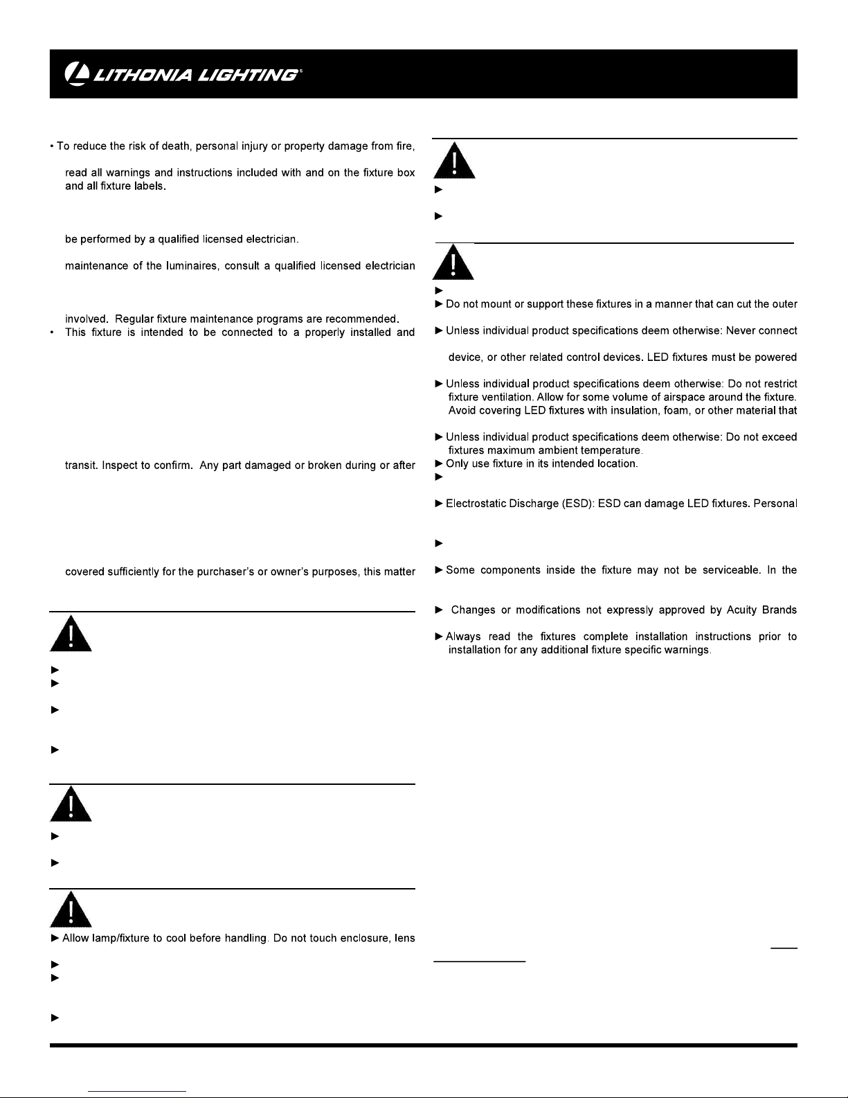
IMPORTANT SAFETY INSTRUCTIONS
READ AND FOLLOW THESE SAFETY INSTRUCTIONS!
electric shock, falling parts, cuts/abrasions, and other hazards please
• Before installing, servicing, or performing routine maintenance upon this
equipment, follow these general precautions.
• Commercial installation, service and maintenance of luminaires should
• For Residential installation: If you are unsure about the installation or
and check your local electical code.
• Maintenance of the luminaires should be performed by person(s)
familiar with the luminaires’ construction and operation and any hazards
grounded UL listed junction box.
• It will occasionally be necessary to clean the outside of the refractor/
lens. Refractor/lens should be washed in a solution of warm water and
any mild, non-abrasive household detergent, rinsed with clean water and
wiped dry. Should optical assembly become dirty on the inside, wipe
refractor/lens and clean in above manner, replacing damaged gaskets
as necessary.
• DO NOT INSTALL DAMAGED PRODUCT! This luminaire has been
properly packed so that no parts should have been damaged during
assembly should be replaced.
• Recycle: For information on how to recycle LED electronic products,
please visit www.epa.gov.
• These instructions do not purport to cover all details or variations
in equipment nor to provide every possible contingency to meet in
connection with installation, operation, or maintenance. Should further
information be desired or should particular problems arise which are not
CAUTION
RISK OF FIRE
Keep combustible and other materials that can burn, away from lamp/
lens.
Do not operate in close proximity to persons, combustible materials or
substances affected by heat.
CAUTION
RISK OF PRODUCT DAMAGE
Never connect components under load.
jacket or damage wire insulation.
an LED product directly to a dimmer packs, occupancy sensor, timing
directly off a switched circuit.
will prevent convection or cooling.
LED products are Polarity Sensitive. Ensure proper Polarity before
installation.
grounding equipment must be worn during all installation or servicing
of unit.
Do not touch individual electrical components as this can cause ESD,
shorten lamp life, or alter performance.
should be referred to Acuity Brands Lighting, Inc.
WARNING
RISK OF ELECTRIC SHOCK
Disconnect or turn off power before installation or servicing.
Verify that supply voltage is correct by comparing it with the luminaire
label information.
Make all electrical and grounded connections in accordance with
the National Electrical Code (NEC) and any applicable local code
requirements.
All wiring connections should be capped with UL approved wire
connectors.
CAUTION
RISK OF INJURY
Wear gloves and safety glasses at all times when removing luminaire
from carton, installing, servicing or performing maintenance.
Avoid direct eye exposure to the light source while it is on.
WARNING
RISK OF BURN
or light source.
Do not exceed maximum wattage marked on luminaire label.
Follow all manufacturer’s warnings, recommendations and restrictions
including but not limited to: driver type, burning position, mounting
locations/methods, replacement and recycling.
Use only lamps that comply with ANSI standards.
unlikely event your unit may require service, stop using the unit
immediately and contact an ABL representative for assistance.
Lighting could void the authority to operate the equipment.
This equipment has been tested and found to comply with the limits for a
class B digital device, pursuant to part 15 of the FCC Rules. These limits
are designed to provide reasonable protection against harmful interference
when used in a residential installation. This equipment generates, uses
and can radiate radio frequency energy and, if not installed and used in
accordance with the instructions may cause harmful interference to radio
communications. However, there is no guarantee that interference will
not occur in a particular installation. If this equipment does cause harmful
interference to radio or television reception, which can be determined by
turning the equipment off and on, the user is encouraged to try to correct
the interference by one or more of the following measures:
• Reorient or relocate the receiving antenna.
• Increase the separation between the equipment and receiver.
• Connect the equipment into an outlet on a circuit different from that to
which the receiver is connected.
• Consult the dealer or an experienced radio/TV technician for help.
5-YEAR LIMITED WARRANTY
Failure to follow any of these instructions could void product warranties.
For a complete listing of product Terms and Conditions, please visit www.
acuitybrands.com. Acuity Brands Lighting, Inc. assumes no responsibilities
for claims arising out of improper or careless installation or handling of its
products.
page 2
Page 3

INSTALLATION INSTRUCTIONS
FIXTURE PACKING LIST
Description Quantity
1) LED Light Fixture................................................................. 1
2) Photocontrol with adjustable cover (PE model only) ........... 1
3) 1-1/4”(2H) & 2”(3H) Mounting Screw ................................. 1
4) Cross Bar ............................................................................ 1
5) 3/4” #8 & #6 & #10 screws* ................................................. 6
6) Wire Nuts* ........................................................................... 3
7) Rubber Plug* ....................................................................... 1
8) Lock Nut ................................................................2 or 3 or 4
9) Adjustment Knob .......................................................... 2 or 3
10) Visor (Round Head only) ............................................. 2 or 3
11) Set Screw (Round Head only) ..................................... 4 or 6
12) Support Hook* .................................................................... 1
*Contained in parts packs
Mounting Hardware Included
Silicone Sealant Required
REQUIRED TOOLS:
Check to
ensure all parts are included. Note: Account for small parts and
destroy packing material, as these may be hazardous to children.
2. Turn OFF Power at circuit breaker box.
CAUTION: Do not rely on wall switch alone to turn off power.
Note: Suitable for wall mount or eave mount.
Not suitable for ground mount installation.
3. Install cross bar (4) to your junction box using two 3/4” #6 or #8
or #10 screws (5) (screw size is depending on your junction box).
4. Hang one end of the support hook (12) onto the cross bar
9) Adjustment Knob
1) LED Light Fixture
4) Cross Bar
7) Rubber Plug
3) Mounting Screw
2) Photocontrol
5) 3/4” Screws
Figure A
20° down below horizontal in order to prevent water from
accumulating inside lens.
After lamp heads are positioned as desired, align the optional
visor (10) over the front of the round lamp head and secure by
tightening the set screws (11) on the visor.
9. Turn on electricity at fuse or circuit breaker box and verify
success of installation. Note: on models with photocell, adjust
photocontrol cover so that the window is fully open. See Trouble
shooing guide for more info.
10. Apply silicone caulking (not included) around the perimeter
moisture seal.
See Fig.B
CAUTION: WIRING AND FIXTURE OPERATION
Make sure power is turned off. Connect to 120V, 60Hz circuit only.
use wire nut (6) to connect the (copper)
If house wiring does not include a ground wire, consult your local
electrical code for approved grounding methods.
For proper connection, place wire nut over wires
and twist clockwise until tight.
6. To Connect supply wires use wire nut (6) to connect the black
wire to the white (neutral) supply wire.
insert mounting screw (3) into center hole of
with rubber plug (7). See Fig A. Note: make sure no wires are
pinched before tightening.
8. Aim lamp heads and install optional visor (round heads)
Each lamphead can be positioned in multiple directions via
the adjustment knob (9) and the lock nut (8). Note: Make sure
to secure all lock nuts and adjustment knobs tightly (do not
CAUTION - Risk of Shock: Aim lamp heads at least
6) Wire Nuts
Note:
12) Support Hook
10) Visor
8) Lock Nut
11) Set Screw
Figure B
page 3
Page 4

Trouble Shooting Guide
to diagnose and correct the problem.
• Verify that power is turned on at switch and breaker
•
• Verify that line voltage is correct (120V)
The photocontrol in the “PE” models is designed to turn on
rotatable cover to allow adjustment of light entry.
Test if Photocontrol works properly:
If light does not come on or stays on:
• Close Photocontrol cover - Light should come on.
•
Photocontrol - Light should go off
TROUBLE SHOOTING GUIDE
light sources enters the photocontol. To correct problem, eliminate
If Photocontrol cover is in closed position, it will allow continuous
If further technical assistance is required, contact: Technical
Support at: (800) 748-5070
This LED light provides low maintenance service with no bulbs
to change. Clean surfaces with mild soap and water. Do not use
abrasive materials such as scouring pads or powders, steel wool
or abrasive paper.
WARNING:
 Loading...