

Page 1
INSTALLATION INSTRUCTIONS
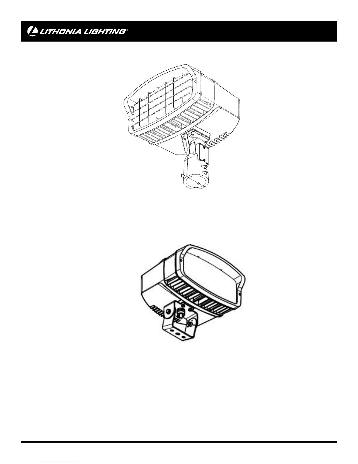
LED Flood Luminaire
Model Number(s):
OFL2 LED IS
OFL2 LED YK
Protect yourself. Before installing, read the entire instructions carefully and save them for future reference.
Date installed:_____________
Failure to follow any of these instructions could void product warranties. For a complete list of product Terms and
Conditions, visit www.acuitybrands.com. Acuity Brands Lighting, Inc. assumes no responsibilities for claims arising out of
improper or careless installation or handling of its products.
If further technical assistance is required, contact: Technical Support at: (800) 279-8041.
page 1
UOFL2_Rev 01/13/16
Page 2
IMPORTANT SAFETY INSTRUCTIONS
READ AND FOLLOW THESE SAFETY INSTRUCTIONS!
• To reduce the risk of death, personal injury or property damage from fi re,
electric shock, falling parts, cuts/abrasions, and other hazards please
read all warnings and instructions included with and on the fi xture box
and all fi xture labels.
• Before installing, servicing, or performing routine maintenance upon this
equipment, follow these general precautions.
• Commercial installation, service and maintenance of luminaires should
be performed by a qualifi ed licensed electrician.
• For Residential installation: If you are unsure about the installation or
maintenance of the luminaires, consult a qualifi ed licensed electrician
and check your local electical code.
• Maintenance of the luminaires should be performed by person(s) familiar
with the luminaires’ construction and operation and any hazards involved.
Regular fi xture maintenance programs are recommended.
• This fi xture is intended to be connected to a properly installed and
grounded UL listed junction box.
• It will occasionally be necessary to clean the outside of the refractor/
lens. Refractor/lens should be washed in a solution of warm water and
any mild, non-abrasive household detergent, rinsed with clean water and
wiped dry. Should optical assembly become dirty on the inside, wipe
refractor/lens and clean in above manner, replacing damaged gaskets
as necessary.
• DO NOT INSTALL DAMAGED PRODUCT! This luminaire has been
properly packed so that no parts should have been damaged during
transit. Inspect to confi rm. Any part damaged or broken during or after
assembly should be replaced.
• Recycle: For information on how to recycle LED electronic products,
please visit www.epa.gov.
• These instructions do not purport to cover all details or variations
in equipment nor to provide every possible contingency to meet in
connection with installation, operation, or maintenance. Should further
information be desired or should particular problems arise which are not
covered suffi ciently for the purchaser’s or owner’s purposes, this matter
should be referred to Acuity Brands Lighting, Inc.
WARNING
RISK OF ELECTRIC SHOCK
► Disconnect or turn off power before installation or servicing.
► Verify that supply voltage is correct by comparing it with the luminaire
label information.
► Make all electrical and grounded connections in accordance with
the National Electrical Code (NEC) and any applicable local code
requirements.
► All wiring connections should be capped with UL approved wire
connectors.
CAUTION
RISK OF INJURY
► Wear gloves and safety glasses at all times when removing luminaire
from carton, installing, servicing or performing maintenance.
► Avoid direct eye exposure to the light source while it is on.
CAUTION
RISK OF FIRE
►Keep combustible and other materials that can burn, away from lamp/
lens.
►Do not operate in close proximity to persons, combustible materials or
substances affected by heat.
CAUTION
RISK OF PRODUCT DAMAGE
► Never connect components under load.
► Do not mount or support these fi xtures in a manner that can cut the outer
jacket or damage wire insulation.
► Unless individual product specifi cations deem otherwise: Never connect
an LED product directly to a dimmer packs, occupancy sensor, timing
device, or other related control devices. LED fi xtures must be powered
directly off a switched circuit.
► Unless individual product specifi cations deem otherwise: Do not restrict
fi xture ventilation. Allow for some volume of airspace around the fi xture.
Avoid covering LED fi xtures with insulation, foam, or other material that
will prevent convection or cooling.
► Unless individual product specifi cations deem otherwise: Do not exceed
fi xtures maximum ambient temperature.
► Only use fi xture in its intended location.
► LED products are Polarity Sensitive. Ensure proper Polarity before
installation.
► Electrostatic Discharge (ESD): ESD can damage LED fi xtures. Personal
grounding equipment must be worn during all installation or servicing
of unit.
► Do not touch individual electrical components as this can cause ESD,
shorten lamp life, or alter performance.
► Some components inside the fi xture may not be serviceable. In the
unlikely event your unit may require service, stop using the unit
immediately and contact an ABL representative for assistance.
► Changes or modifi cations not expressly approved by Acuity Brands
Lighting could void the authority to operate the equipment.
► Always read the fi xtures complete installation instructions prior to
installation for any additional fi xture specifi c warnings.
This equipment has been tested and found to comply with the limits for a
class B digital device, pursuant to part 15 of the FCC Rules. These limits
are designed to provide reasonable protection against harmful interference
when used in a residential installation. This equipment generates, uses
and can radiate radio frequency energy and, if not installed and used in
accordance with the instructions may cause harmful interference to radio
communications. However, there is no guarantee that interference will
not occur in a particular installation. If this equipment does cause harmful
interference to radio or television reception, which can be determined by
turning the equipment off and on, the user is encouraged to try to correct
the interference by one or more of the following measures:
• Reorient or relocate the receiving antenna.
• Increase the separation between the equipment and receiver.
• Connect the equipment into an outlet on a circuit different from that to
which the receiver is connected.
• Consult the dealer or an experienced radio/TV technician for help.
WARNING
RISK OF BURN
► Allow lamp/fi xture to cool before handling. Do not touch enclosure, lens
or light source.
► Do not exceed maximum wattage marked on luminaire label.
► Follow all manufacturer’s warnings, recommendations and restrictions
including but not limited to: driver type, burning position, mounting
locations/methods, replacement and recycling.
► Use only lamps that comply with ANSI standards.
Register your warranty on www.acuitybrands.com/resources/warranty.
5-YEAR LIMITED WARRANTY
Your prompt product registration confi rms your right to the protection
available under the terms and conditions of your Lithonia Lighting
warranty.
Failure to follow any of these instructions could void product warranties.
For a complete listing of product Terms and Conditions, please visit www.
acuitybrands.com. Acuity Brands Lighting, Inc. assumes no responsibilities
for claims arising out of improper or careless installation or handling of its
products.
page 2
Page 3
INSTALLATION INSTRUCTIONS
Upon receipt of fi xture, thoroughly inspect for any freight damage.
All damage should be reported to the delivery carrier. Compare
the catalog description listed on the packing slip with the fi xture
label on the inside of the housing to be sure you have received
the correct merchandise. Note: Account for small parts and
destroy packing material, as these may be hazardous to children.
Turn OFF Power at circuit breaker box.
CAUTION: Do not rely on wall switch alone to turn off power.
OFL2 IS - Integral Slipfi tter Mounting:
Required Tools: 1/4” and 3/16” hex socket driver and fl at head
screwdriver.
Remove the cover plate to access the integral wiring compartment
using a fl at head screwdriver or 1/4” hex socket driver. Place
integral slipfi tter onto 2-3/8” diameter Tenon ensuring that the
wires are pulled through the integral wiring compartment without
pinching. Secure slipfi tter to the Tenon by tightening the 3/8” hex
socket set screws using a 3/16 hex socket driver. Make supply
connections through the integral wiring compartment. Refer to
wiring instructions on next page for power connection. Push wires
into compartment and re-install cover plate. To adjust the tilt angle
of the fi xture, loosen the 1/4” hex socket screw above the integral
wiring compartment. Rotate fi xture to desired angle and re-tighten
center screw.
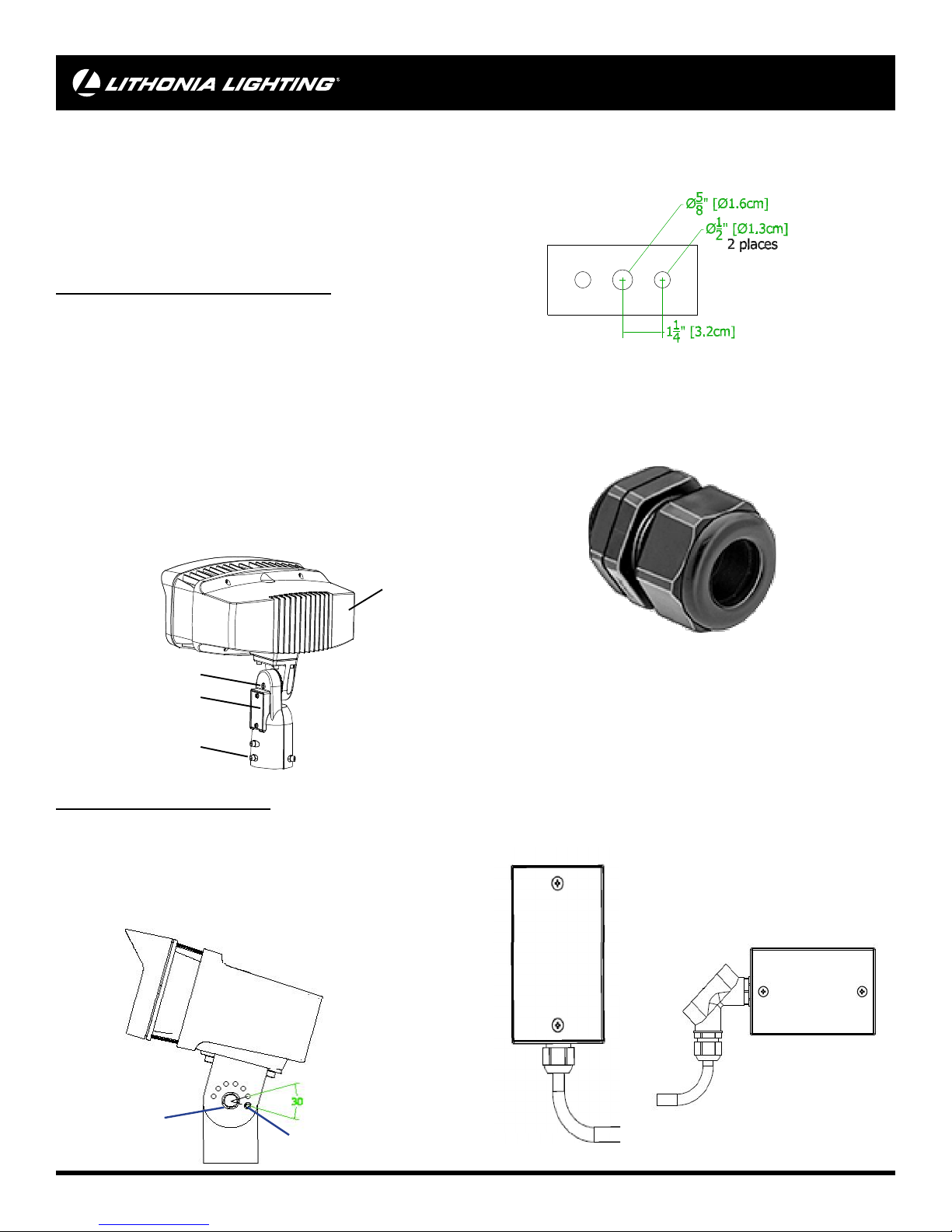
Mount fi xture to the desired bracketry using the hole pattern
provided on the yoke bracket (see template below) with a 5/8” bolt
(if center hole is used) or 1/2” bolts (if outer holes are used), lock
washer, and nut (not provided). Tighten to 30ft-lbs.
The Yoke Mounting option is provided with 16AWG power supply
cord. The power supply cord has 0.4 inch outside diameter (O.D.).
A UL LISTED water tight cord connector suitable for use on 0.4
inch diameter size wet location fl exible cord shall be required in
order to install onto an outdoor junction box. See image below.
OLF2 IS
1/4” hex socket screw
cover plate
3/8” hex socket set
screws (4plcs)
OFL1&2 YK - Yoke Mounting:
Required Tools: Hex socket driver and regular screwdriver.
To adjust the tilt angel of the fi xture, loosen but do not remove
the 3/8” hex bolts on both sides of the yoke. While holding weight
of fi xture, remove 10-32” set screw, adjust to desired angle and
reinstall set screw in appropriate matching hole. Re-ighten hex
bolts to secure.
When installing onto an outdoor junction box and in order to
reduce risk of water entry, ensure that a Tefl on tape or silicone
sealant is applied on the threaded portion of the fi tting when being
installed. It is recommended that the water tight cord connector
be installed so that power supply cord exits towards the ground.
If existing wiring does not allow for installation of wires exiting
towards the ground, the use of an elbow suitable for wet location
use is recommended so that cord can exit towards the ground.
See images below. Refer to wiring instructions on next page for
power connection.
3/8” Hex bolt (2
plcs) use 9/16
socket driver
10-32” set screw
page 3
Page 4
TROUBLE SHOOTING GUIDE
ACCESSORIES (sold separately)
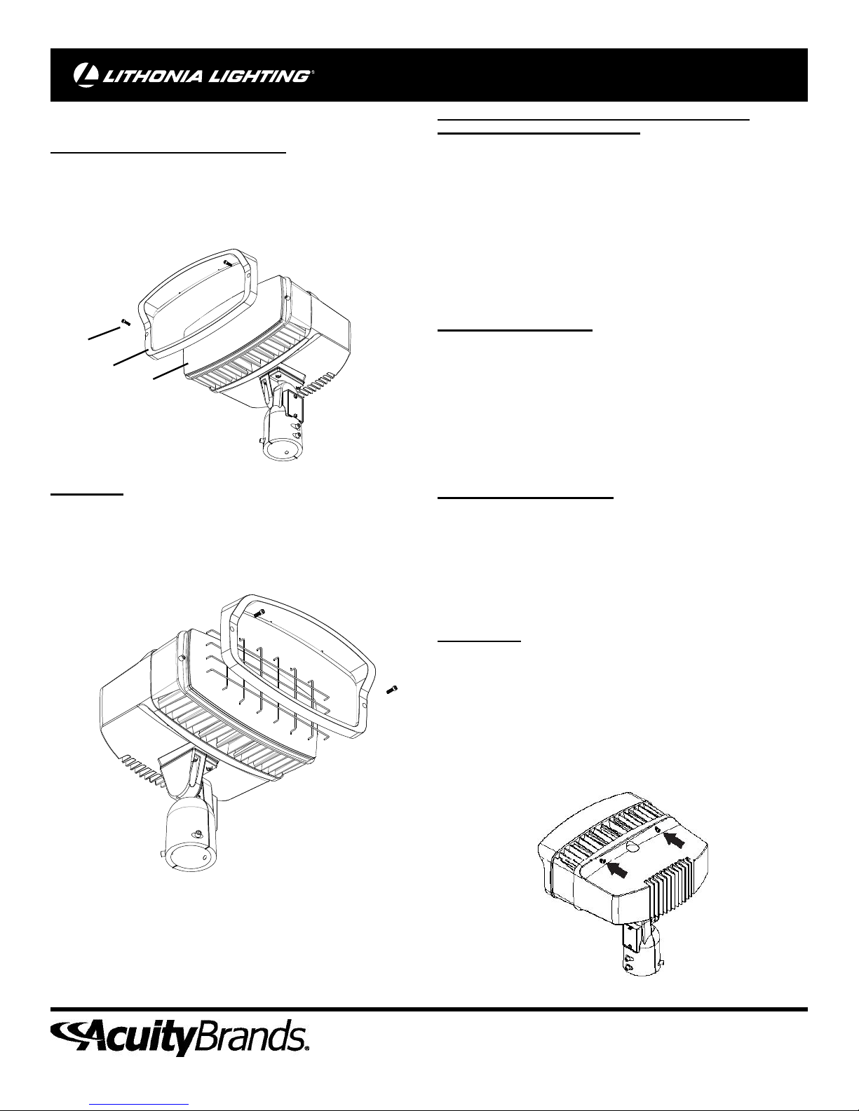
Vandalguard (polycarbonate shield)
To install vandalguard, unscrew the (2) 10-24 socket head screws
on the front face of the bezel and remove bezel. Replace glass
lens with vandalguard and re-install bezel. Note: do not touch
LED
screw (2)
bezel
lens
Wireguard
To install wireguard, unscrew the (2) 10-24 socket head screws
on the front face of the bezel and remove bezel. Insert Wireguard
and re-install bezel. Note: do not remove glass or touch LED
CAUTION: WIRING AND FIXTURE OPERATION
Make sure power is turned off.
To Ground fi xture use Wire Nut to connect the (copper) house
supply ground wire & the (green) fi xture ground wire. Note: If
house wiring does not include a ground wire, consult your local
electrical code for approved grounding methods.
For proper connection, place wire nut over
wires and twist clockwise until tight.
To connect supply wires use Wire Nuts to connect the black
fi xture wire to the black power supply wire and the white fi xture
wire to the white (neutral) supply wire.
Trouble Shooing Guide
If this fi xture fails to operate properly, use the guide below to
diagnose and correct the problem.
• Verify that power is turned on at switch and breaker
• Verify that fi xture is wired properly
• Verify that line voltage is correct
If further assistance is required, contact:
Technical Support at: (800) 279-8041
Cleaning and Maintenance
Caution: Be sure fi xture temperature is cool enough to touch. Do
not clean or maintain while fi xture is energized.
This LED light provides low maintenance service with no bulbs
to change. Clean surfaces with mild soap and water. Do not use
abrasive materials such as scouring pads or powders, steel wool
or abrasive paper.
Do not touch LED.
Driver Access
The driver is pre-wired so access to the driver during installation
is uncessary but in case of a driver failure the driver can be
accessed and replaced. To access the driver compartment,
unscrew the (4) 10-24 socket head screws in the back of the
housing and remove the bezel and heatsink assembly.
Acuity Brands Lighting, Inc.
One Lithonia Way, Conyers, GA 30012
www.AcuityBrands.com
Page 5

E S PA Ñ O L
Refl ector de led
Número de modelo:
GUÍA DE PASO-A-PASO
OFL2 LED IS
OFL2 LED YK
Antes de instalar, lea estas instrucciones cuidadosamente y guárdelas para futura referencia.
Fecha Instalada:_____________
El incumplimiento de alguna de estas instrucciones puede anular la garantía del producto. Para obtener la lista completa
de los términos y las condiciones respecto al producto, visite www.acuitybrands.com. Acuity Brands Lighting, Inc. no se
hace responsable por los reclamos que puedan surgir de la instalación o manipulación inadecuada o negligente de sus
productos.
Si necesita obtener más ayuda técnica, comuníquese con: Soporte técnico al: (800) 279-8041
page 5
UOFL2_Rev 01/13/16
Page 6

INFORMACIÓN IMPORTANTE DE SEGURIDAD
E S PA Ñ O L
LEA Y SIGA LAS INSTRUCCIONES DE INSTALACIÓN.
• Para reducir el riesgo de muerte, lesiones personales o daño a la
propiedad que pueda surgir de incendios, choques eléctricos, cortes,
abrasiones, caída de partes y otros peligros lea todas las advertencias e
instrucciones incluidas en la caja o su interior, además de las etiquetas
del montaje.
• Antes de instalar o revisar el equipo, o realizar mantenimiento de rutina,
siga estas precauciones generales.
• La instalación, la revisión y el mantenimiento comerciales de las
luminarias debe ser realizada por un electricista califi cado autorizado.
• La En el caso de instalaciones residenciales: Si no está seguro sobre
la instalación o el mantenimiento de las luminarias, consulte a un
electricista califi cado autorizado y verifi que el código eléctrico local.
• Este montaje ha sido diseñado para conectarse a una caja de unión
aprobada por UL debidamente instalada y puesta a tierra.
• Cada tanto será necesario limpiar la parte externa del refractor y de la
lente. La frecuencia de la limpieza dependerá del nivel de polvo del
ambiente y de la potencia de la luz mínima aceptable para el usuario.
El refractor/la lente se debe lavar con una solución de agua tibia y
detergente de uso doméstico suave no abrasivo, enjuagar con agua
limpia y secar. Si el montaje óptico se ensuciara por dentro, limpie el
refractor o la lente como se indicó anteriormente; de ser necesario,
reemplace las juntas dañadas.
• NO INSTALE EL PRODUCTO SI ESTÁ DAÑADO
• Reciclado: Para obtener información sobre cómo reciclar productos
electrónicos LED, visite www.epa.gov.
• Estas instrucciones no pretenden cubrir todos los detalles o las
variaciones de los equipos ni abarcar todas las posibles eventualidades
relacionadas con la instalación, el funcionamiento o el mantenimiento.
Si necesita más información o surgen problemas específi cos que no
están debidamente cubiertos en la información del producto, remítase a
Acuity Brands Lighting, Inc.
ADVERTENCIA
RIESGO DE CHOQUE ELÉCTRICO
► Desconecte o interrumpa la energía eléctrica antes de realizar la
instalación o la reparación.
► Verifi que que el voltaje de alimentación sea correcto; compárelo con la
información de la etiqueta de la luminaria.
► Realice todas las conexiones eléctricas y a tierra en cumplimiento del
Código Eléctrico Nacional y de los requisitos del código local vigente.
► Todas las conexiones de cableado deben cubrirse con conectores para
cable reconocidos y aprobados por UL.
PRECAUCIÓN
RIESGO DE LESIONES
► Use gafas y guantes de protección en todo momento al retirar la
luminaria de la caja, al instalarla, repararla o realizar operaciones de
mantenimiento.
► Una vez encendida la fuente de luz, evite la exposición directa con los
ojos.
ADVERTENCIA
RIESGO DE QEUEMADURAS
► Antes de manipular el montaje, déjelo enfriar. No toque la carcasa ni la
fuente de iluminación.
► No supere el voltaje máximo señalado en la etiqueta de la luminaria.
► Respete todas las advertencias, recomendaciones y restricciones
que proporciona el fabricante para: tipo de conductor, posición de
funcionamiento, puntos o métodos de montaje, reemplazo y reciclado.
► Use sólo lámparas que cumplan los estándares ANSI.
PRECAUCIÓN
RIESGO DE INCENDIO
► Mantenga lejos de la luminaria y de las lámparas/lentes, los materiales
combustibles y de otro tipo que se puedan incendiar.
► No las encienda cerca de personas, materiales combustibles o
sustancias infl amables.
PRECAUCIÓN
RIESGO DE DAÑO PARA EL PRODUCTO
► Jamás conecte componentes bajo carga.
► No monte estos montajes de manera que puedan cortar el revestimiento
exterior o dañar el aislamiento de los cables.
► A menos que las especifi caciones del producto individual consideren lo
contrario: jamás conecte un producto LED directamente a un paquete de
reducción de intensidad de la luz, sensores de ocupación, dispositivos
de temporización ni demás dispositivos de control relacionados.
Los montajes LED se deben apagar directamente de un circuito de
interruptores.
► A menos que las especifi caciones del producto individual consideren lo
contrario: no limite la ventilación del montaje. Deje un poco de espacio
alrededor del montaje. Evite cubrir los montajes LED con aislación,
goma u otro material que evitará la convección o el enfriamiento de la
conducción.
► A menos que las especifi caciones del producto individual consideren lo
contrario: no supere la temperatura ambiente máxima para el montaje.
► Use el montaje sólo en la ubicación para la que está diseñado.
► Los productos LED son sensibles a la polaridad. Asegure la correcta
polaridad antes de la instalación.
► Descarga electrostática (DES): la DES puede dañar los montajes LED.
Durante la instalación o reparación de la unidad se debe usar siempre
equipo personal conectado a tierra.
► No toque componentes eléctricos individuales ya que esto puede causar
DES, reducir la vida útil de la lámpara o alterar el funcionamiento.
► Es posible que algunos componentes dentro del montaje no se puedan
reparar. En el caso improbable de que su unidad requiera reparación,
deje de usar la unidad inmediatamente y comuníquese con un
representante de ABL para obtener ayuda.
► Los cambios o modifi caciones no aprobados expresamente por Acuity
Brands Lighting pueden anular la autoridad del usuario para usar el
equipo.
► Lea siempre las instrucciones de instalación completa de montaje
antes de la instalación para verifi car si hay advertencias específi cas de
montaje adicionales.
Este equipo se ha probado y se ha encontrado para conformarse con los
límites para un dispositivo de la clase B digital, conforme a la parte 15
de las reglas de la FCC. Estos límites se diseñan para proporcionar la
protección razonable contra interferencia dañosa cuando están utilizados
en una instalación residencial. Este equipo genera, las aplicaciones y puede
irradiar energía de la radiofrecuencia. Si no instalado y utilizado de acuerdo
con el manual de la instrucción, este equipo puede causar interferencia
dañosa a las comuncaciones por radio. La operación está conforme a las
dos condiciones siguientes.
Sin embargo, no se puede garantizar que no se produzcan interferencias
en una instalación en particular. Si este equipo ocasionara interferencias
perjudiciales para la recepción de las señales de radio o televisión, las que
pueden detectarse al encender y apagar el equipo, el usuario debe intentar
corregirlas por medio de una de las siguientes medidas:
• Orientar la antena receptora en otra dirección o ubicarla en otro sitio.
• Aumentar la separación entre el equipo y el receptor.
• Conectar el equipo a una toma de corriente de un circuito diferente del
que esté conectado al receptor.
• Solicitar ayuda al comerciante o a un técnico experto en radio/TV.
GARANTÍA LIMITADA POR 5 AÑOS
El incumplimiento de alguna de estas instrucciones puede anular la
garantía del producto. Para obtener la lista completa de los términos
y las condiciones respecto al producto, visite www.acuitybrands.com.
Acuity Brands Lighting, Inc. no se hace responsable por los reclamos que
puedan surgir de la instalación o manipulación inadecuada o negligente
de sus productos.
page 6
Page 7

GUÍA DE PASO-A-PASO
E S PA Ñ O L
Cuando reciba el aparato, inspeccione minuciosamente para
detectar posibles daños por el envío. Informe todos los daños
a la compañía a cargo del envío. Compare la descripción de
catálogo incluida en el comprobante de empaque con la etiqueta
del aparato en el interior del paquete para asegurarse de haber
recibido la mercadería correcta. Note: Nota: Tenga cuidado con
las piezas pequeñas y destruya el material de embalaje, ya que
pueden ser peligrosos si están al alcance de niños.
¡Apague la electricidad en la caja de rtacircuitos!
ATENCIÓN: No se confi e de cortar la corriente en el interruptor
mural solamente.
OFL2 IS - Montaje del posicionador deslizante integral:
HERRAMIENTAS REQUERIDAS: 1/4” and 3/16” hex socket
driver and fl at head screwdriver.
Retire la placa de cubierta para acceder al compartimento de
cableado integral con un destornillador de punta plana o con una
llave hexagonal de 1/4 in. Coloque el posicionador deslizante
integral en la espiga de 2-3/8 in de diámetro y asegúrese de
que los cables se tiren a través del compartimento de cableado
integral sin apretarlos. Asegure el posicionador deslizante a la
espiga ajustando los tornillos de fi jación de cabeza hexagonal
de 3/8 in con una llave hexagonal 3/16. Realice las conexiones
eléctricas a través del compartimento de cableado integral.
Consulte las instrucciones de cableado en la página siguiente
para la conexión de alimentación. Empuje los cables en el
compartimento y vuelva a instalar la placa de cubierta. Para
ajustar el ángulo de inclinación del aparato, afl oje el tornillo
de cabeza hexagonal de 1/4 in que se encuentra sobre el
compartimento de cableado integral. Gire el aparato hacia el
ángulo deseado y vuelva a ajustar el tornillo central.
Monte el aparato en el soporte deseado utilizando el patrón de
agujeros previsto en el soporte de yugo (consulte el modelo
a continuación) con un perno de 5/8 in (si se utiliza el orifi cio
central) o con pernos de 1/2 in (si se utilizan los agujeros
exteriores), con la arandela de bloqueo y con la tuerca (no
incluida). Ajuste a 30 ft-lb.
La opción de montaje de yugo viene con un cable de alimentación
de 16 AWG. El cable de alimentación tiene un diámetro exterior
(OD) de 0,4 pulgadas. Para realizar una instalación en una caja
de conexiones al aire libre, se requiere de un conector de cable
impermeable CERTIFICADO POR LA UL que sea compatible
con un cable fl exible para lugares húmedos de 0,4 pulgadas de
diámetro. Consulte la imagen que aparece más abajo.
OLF2 IS
1/4” hex socket screw
cover plate
3/8” hex socket set
screws (4plcs)
OFL1&2 YK - Montaje del yugo:
HERRAMIENTAS REQUERIDAS: Hex socket driver and regular
screwdriver.
Para ajustar el ángulo de inclinación del aparato, afl oje, pero no
quite, los pernos hexagonales de 3/8 in de ambos lados del yugo.
Mientras sostiene el peso del aparato, retire el tornillo de fi jación
de cabeza hexagonal 10-32 , ajuste hacia el ángulo deseado
y vuelva a instalar el tornillo de cabeza hexagonal en el lugar
correspondiente. Vuelva a ajustar los pernos hexagonales para
asegurar.
Cuando se realiza una instalación en una caja de conexiones
al aire libre y con el fi n de reducir el riesgo de entrada de agua,
asegúrese de que la cinta de tefl ón o el sellador de silicona se
apliquen sobre la parte roscada de la conexión. Se recomienda
que el conector del cable impermeable se instale de modo que
el cable de alimentación salga hacia el suelo. Si el cableado
existente no permite la instalación de cables que salgan hacia el
suelo, se recomienda utilizar un codo apto para lugares húmedos
para que el cable pueda salir hacia el suelo. Consulte la imagen
que aparece más abajo. Consulte las instrucciones de cableado
en la página siguiente para la conexión de alimentación.
3/8” Hex bolt (2 plcs)
use 9/16 socket driver
10-32” set screw
page 7
Page 8

E S P A Ñ O L
GUÍA DE LOCALIZACIÓN DE AVERÍAS
ACCESORIOS (se venden por separado)
Rejilla de protección (escudo de policarbonato)
Para instalar la rejilla de protección, desenrosque los (2) tornillos
de cabeza Allen 10-24 en la parte frontal del bisel y retire el bisel.
Vuelva a colocar la lente de cristal con la rejilla y vuelva a instalar
el bisel. Nota: No toque el led
screw (2)
bezel
lens
Rejilla de protección
Para instalar la rejilla de protección, desenrosque los (2) tornillos
de cabeza Allen 10-24 en la parte frontal del bisel y retire el bisel.
Inserte la rejilla de protección y vuelva a instalar el bisel. Nota: No
quite el vidrio ni toque el led.
PRECAUCIÓN: OPERACIÓN DEL LUMINARIO Y ALAMBRADO
Cerciórese que la fuente de alimentación eléctrica este apagada.
Para poner a tierra el luminario, utilice una Tuerca de Alambres
para conectar el alambre de tierra de suministro de la casa y el
alambre (cobre) de tierra del luminario (verde).
Nota: Si el alambrado de la casa no incluye un alambre de
Conexión a Tierra, consulte su código eléctrico local para
métodos aprobados para conectar a tierra.
Para una conexión apropiada, coloque el capuchón
de alambre sobre los alambres y gire en el sentido
de las agujas del reloj hasta que este apretado.
CONEXIÓN DEL SUMINISTRO ELÉCTRICO
Use capuchones de alambres para conectar los dos alambres
negro del luminario al alambre negro del suministro de
electricidad de la casa y los dos alambres blanco del luminario al
blanco (neutral) del suministro de electricidad de la casa.
Guía de Localización de Averías
Si este luminario falla de operar apropiadamente, use la
siguiente guía para diagnosticar y corregir el problema.
• Verifi que que el luminario este alambrado apropiadamente.
• Verifi que que el luminario este conectado tierra correctamente.
• El voltaje de la linea en el luminario este correcto.
Si necesita obtener más ayuda técnica, comuníquese con:
Soporte técnico al: (800) 279-8041.
Limpieza y mantenimiento
Precaución: Asegúrese de que la temperatura del aparato
es lo sufi cientemente fría para tocarlo. No limpie ni realice
mantenimiento mientras el aparato está encendido.
Esta lámpara LED con detector de movimiento necesita
muy poco mantenimiento y no es necesario cambiar los
focos. Limpie las superfi cies con un limpiador suave no
abrasivo. No toque el led.
Acceso al controlador
El controlador está precableado para que no sea necesario el
acceso al controlador durante la instalación, pero en caso de
un fallo, se puede acceder y reemplazarlo. Para acceder al
compartimento del controlador, desenrosque los (4) tornillos de
cabeza Allen 10-24 en la parte posterior de la carcasa, y retire el
conjunto del bisel y el disipador de calor.
Acuity Brands Lighting, Inc.
One Lithonia Way, Conyers, GA 30012
www.AcuityBrands.com
Page 9

DIRECTIVES D’INSTALLATION
Luminaire à projecteur DEL
F r a n ç a i s
Numéro des modèle
OFL2 LED IS
OFL2 LED YK
Pour votre propre protection. Avant de procéder à l’installation, veuillez lire attentivement ces directives et les
conserver pour référence ultérieure. Date de l’installation :__________________
Tout manquement au respect de ces instructions pourrait rendre nulles les garanties. Pour une liste complète des
conditions générales du produit, veuillez vous rendre sur www.acuitybrands.com. Acuity Brands Lighting, Inc. n’assume
aucune responsabilité pour les réclamations découlant d’une installation ou d’une manipulation incorrectes ou négligentes
de ses produits.
Pour toute autre assistance, veuillez contacter nos services de support technique: le soutien technique au: (800) 279-8041
page 9
UOFL2_Rev 01/13/16
Page 10

VEUILLEZ LIRE ET RESPECTER TOUTES LES CONSIGNES DE SÉCURITÉ!
• Afi n de réduire le risque de blessures personnelles ou de mort, ou
d’endommager le matériel en raison d’un incendie, d’un choc électrique,
de la chute de pièces, de coupures/abrasions ou de tout autre danger,
lisez tous les avertissements et instructions compris dans et sur la boîte
de la fi xation et toutes ses étiquettes.
• Avant d’installer, d’entretenir ou de réaliser une maintenance de routine
sur cet équipement, tenez compte de ces précautions générales.
• L’installation commerciale, l’entretien et les réparations des lampes ne
devraient être effectuées que par un électricien diplômé et qualifi é.
• Pour les installations résidentielles : Si vous avez des doutes quant à
l’installation ou l’entretien des lampes, consultez un électricien diplômé
et qualifi é et vérifi ez votre code de l’électricité local.
• Ce luminaire est conçu pour être connecté à une boîte de jonction
certifi ée UL, correctement installée et mise à la terre.
• Il sera occasionnellement nécessaire de nettoyer la partie extérieure
du réfracteur/de la lentille. Le réfracteur/la lentille doit être lavé(e) dans
une solution d'eau tiède et avec un détergent ménager doux et non
abrasif, puis rincé(e) à l'eau claire et essuyé(e). En cas d'accumulation
de saletés à l'intérieur de l'ensemble optique, essuyez le réfracteur/la
lentille et nettoyez comme indiqué ci-dessus, en remplaçant les joints
endommagés selon le besoin.
• N’INSTALLEZ PAS UN PRODUIT ENDOMMAGÉ !
• Recyclage : pour des informations sur la manière de recycler les produits
électroniques à DEL, veuillez vous rendre sur www.epa.gov.
• Ces instructions ne sont pas censée couvrir tous les détails ou variations
de l’équipement ni fournir toutes les éventualités possibles en ce qui
concerne l’installation, l’utilisation ou l’entretien. Si des informations
supplémentaires devaient s’avérer nécessaires, ou si des problèmes
particuliers se présentent et ne sont pas suffi samment repris pour
l’acheteur ou du propriétaire, il conviendra de contacter Acuity Brands
Lighting, Inc à ce sujet.
AVERTISSEMENT
RISQUE DE CHOC ÉLECTRIQUE
► Débranchez ou coupez l’alimentation avant l’installation ou l’entretien.
► Vérifi ez que la tension d’alimentation est correcte en la comparant avec
les informations sur l’étiquette de la lampe.
► Réalisez tous les raccordements électriques et de masse conformément
aux exigences du Code national de l’électricité et de tout code local
applicable.
► Tous les raccordements câblés doivent être faits avec des connecteurs
de câbles certifi és UL.
ATTENTION
RISQUE DE BLESSURE
►Portez des gants et des lunettes de protection en permanence lorsque
vous retirez la lampe du carton et que vous procédez à l’installation, à
l’entretien ou à des réparations.
►Évitez le contact direct des yeux avec la source de lumière lorsqu’elle
est allumée.
AVERTISSEMENT
RISQUE DE BRÛLURE
► Laissez refroidir la fi xation avant de la manipuler. Ne touchez pas
l’enceinte ou la source de lumière.
► Ne dépassez pas la puissance maximum indiquée sur l’étiquette de la
lampe.
► Respectez tous les avertissements, recommandations et restrictions du
fabricant de lampe pour le circuit d’attaque, la position de fonctionnement,
les méthodes/endroits de montage, le remplacement et le recyclage.
► Utilisez uniquement les lampes qui sont conformes aux normes ANSI.
ATTENTION
RISQUE D’INCENDIE
► Conservez les matériaux combustibles et tout autre élément pouvant
prendre feu à l’écart de la lampe/lentille.
► Ne l’utilisez pas à proximité de personnes, de matériaux combustibles ou
de substances affectées par la chaleur.
F r a n ç a i s
IMPORTANTES MESURES DE SÉCURITÉ
ATTENTION
RISQUE D’ENDOMMAGEMENT DU PRODUIT
► Ne connectez jamais des composants sous charge.
► Ne montez ni soutenez pas ces fi xations d’une manière qui pourrait
sectionner la gaine extérieure ou endommager l’isolation de câble.
► Sauf si contraire aux spécifi cations du produit individuel : ne connectez
jamais un produit à DEL directement à des packs de gradation de la
lumière, des capteurs d’occupation, des dispositifs de minuterie ou
d’autres dispositifs de commande liés. Les fi xations DEL doivent être
alimentées directement hors d’un circuit à interrupteur.
► Sauf si contraire aux spécifi cations du produit individual : Sauf si contraire
aux spécifi cations du produit individuel : ne pas limiter la ventilation de
la fi xation. Laissez un espace libre suffi sant autour de la fi xation. Évitez
de couvrir les fi xations DEL avec de l’isolation, de la mousse ou d’autres
matériaux qui empêcheront le refroidissement de convection ou de
conduction.
► Sauf si contraire aux spécifi cations du produit individuel : ne pas
dépasser la température ambiante maximum à laquelle les fi xations
sont exposées.
► N’utilisez la fi xation que dans l’emplacement prévu à cet effet.
► Les produits à DEL sont sensibles à la polarité. Assurez-vous que la
polarité est correcte avant l’installation.
► Décharge électrostatique (DES) : les DES peuvent endommager les
fi xations DEL. Un équipement de mise à la masse personnel doit être
porté lors de toute installation ou entretien de l’unité.
► Ne touchez pas les composants électriques individuels car cela peut
causer une DES, réduire la durée de vie de la lampe ou altérer ses
performances.
► Certains composants à l’intérieur de la fi xation peuvent ne pas être
réparables. Dans le cas peut probable où votre unité aurait besoin
d’être réparée, arrêtez immédiatement d’utiliser l’unité et contactez un
représentant ABL pour obtenir de l’aide.
► Les changements ou les modifi cations qui ne sont pas expressément
approuvés par Acuity Brands Lighting pourraient rendre nulle et non
avenue l’autorisation d’utiliser ce matériel.
► Lisez toujours les instructions d’installation complètes des fi xations avant
l’installation pour les autres avertissements spécifi ques de la fi xation.
cet équipement a été testé et respecte les limites des normes relatives aux
articles numériques de Classe B établies dans la partie 15 du règlement de
la FCC. Ces limites ont été établies pour offrir une protection raisonnable
contre les interférences nuisibles dans les installations résidentielles. Cet
appareil génére, utilise et peut émettre de l’énergie de radio fréquence.
S’il n’est pas installé de maniére conforme aux instructions, il peut causer
des interférence nuisibles aux communications radio. Il n’est toutefois
pas garanti que de l’interférence ne se produira pas dans une installation
dommée. Si cet équipement cause de l’interférence nuisibles à la réception
radiophonique ou télévisulle, ce qui peut être déterminé en allumant et
en éteignant l’équipment, l’utilisateur est encouragé à suivre l’une ou
l’ensemble des mesures suivantes pour corriger interférence :
• Réorienter ou déplacer l’antenne réceptrice.
• Accroêitre la séparation entre l’équipement et le récepteur.
• Brancher l’équipement sur une prise utilisant un circuit d’alimentation
différent de celui sur lequel le récepteur est connecté.
• Demander l’aide du concessionnaire ou d’un technicien expert dans
les la radio et de la télévision.
GARANTIE LIMITÉE DE 5 ANS
Tout manquement au respect de ces instructions pourrait rendre nulles les
garanties. Pour une liste complète des conditions générales du produit,
veuillez vous rendre sur www.acuitybrands.com. Acuity Brands Lighting,
Inc. n’assume aucune responsabilité pour les réclamations découlant
d’une installation ou d’une manipulation incorrectes ou négligentes de ses
produits.
page 10
Page 11

F r a n ç a i s
GUIDE DÉTAILLÉ
Lors de la réception du luminaire, procéder à une inspection
minutieuse à la recherche de dommages éventuels subis
lors du transport Tous les dommages doivent être signalés
au transporteur livreur. Comparez la description du catalogue
indiquée sur le bordereau d’emballage avec l’étiquette du
luminaire à l’intérieur du boîtier afi n de vous vous assurez que
vous avez reçu les bonnes marchandises. Note: Faites attention
aux petites pièces et détruisez le matériel d’emballage car ils
pourraient être dangereux pour les enfants.
Couper l’électricité au fusible ou au disjoncteur!
ATTENTION: Ne coupez pas le courant uniquement au niveau de
l’interrupteur mural.
OFL2 IS OUTILS REQUIS: 1/4” and 3/16” hex socket driver and flat head screwdriver.
Retirer la plaque de protection pour accéder au boîtier de câblage
complet à l’aide d’un tournevis plat ou d’un tournevis à six pans
de 1/4 po. Placer l’adaptateur d’emboîtement complet dans un
tenon de 2-3/8 po de diamètre en s’assurant que les câbles
passent par le boîtier de câblage complet sans aucun pincement.
Bien fi xez l’adaptateur d’emboîtement au tenon en serrant les
vis à six pans de calage de 3/8 po à l’aide d’un tournevis à six
pans de 3/16 po. Effectuer les raccordements d’alimentation à
travers le boîtier de câblage complet. Consulter les instructions de
câblage du connecteur d’alimentation à la page suivante. Placer
les câbles dans le boîtier et remettre la plaque de protection. Pour
ajuster l’angle d’inclinaison du luminaire, desserrer la vis à six
pans de 1/4 po sur le dessus du boîtier de câblage complet. Faire
pivoter le luminaire jusqu’à l’angle souhaité et resserrer la vis
centrale.
Montage de l’adaptateur d’emboîtement complet :
Fixer le luminaire sur le support souhaité à l’aide des orifi ces
fournis sur le support de la culasse (voir modèle ci-dessous)
avec un boulon de 5/8 po (si un boulon central est utilisé) ou des
boulons de 1/2 po (si des boulons extérieurs sont utilisés), une
rondelle de sécurité et un écrou (non fournis). Serrer jusqu’à
30 pi-lb.
L’option de montage Yoke est fournie avec un cordon
d’alimentation de 16 AWG. Le diamètre extérieur du cordon
d’alimentation est de 0,91 cm (0,4 po). Un connecteur de
cordon étanche à l’eau homologuée UL compatible à la taille de
diamètre de 0,91 cm (0,4 po)du cordon souple en endroit mouillé
est nécessaire pour une installation sur une boîte de jonction
extérieure. Voir image ci-dessous.
OLF2 IS
1/4” hex socket screw
cover plate
3/8” hex socket set
screws (3plcs)
OFL1&2 YK - Montage de la culasse :
OUTILS REQUIS: Hex socket driver and regular screwdriver.
Pour ajuster l’angle d’inclinaison du luminaire, desserrer sans
retirer les boulons hexagonaux de 3/8 po des deux côtés de la
culasse. Tout en soutenant le luminaire, retirer la vis de calage
à tête hexagonale de 10-32 po, ajuster jusqu’à l’angle souhaité
et replacer la vis de calage à tête hexagonale dans le trou
correspondant approprié. Resserrer les boulons hexagonaux à
fond.
Lors d’une installation sur une boîte de jonction extérieure, et
dans le but de réduire le risque d’infi ltration d’eau, veiller à ce
qu’un ruban de téfl on ou de silicone soit appliqué sur la partie
fi letée du raccord à l’installation. Il est recommandé que le
connecteur de cordon étanche soit installé de façon à ce que
le cordon d’alimentation sorte vers le sol. Si le câblage existant
ne permet pas une installation où le fi ls sort vers le sol, il est
recommandé d’utiliser un coude adapté pour une utilisation
dans les endroits mouillé afi n que le cordon puisse sortir vers le
sol. Voir les images ci-dessous. Consulte las instrucciones de
cableado en la página siguiente para la conexión de alimentación.
Consulter les instructions de câblage du connecteur d’alimentation
à la page suivante.
3/8” Hex bolt
(2 plcs) use
9/16 socket
10-32” set screw
page 11
Page 12

GUIDE DE DÉPANNAGE
F r a n ç a i s
ACCESSOIRES (vendus séparément)
Protection contre le vandalisme (protection en polycarbonate)
Pour placer une protection contre le vandalisme, dévisser les
(2) vis à tête creuse de 10-24 sur la partie avant de la lunette et
retirer la lunette. Remplacer la lentille en verre par la protection
contre le vandalisme et replacer la lunette.
screw (2)
bezel
lens
Grille de protection
Pour placer une protection contre le vandalisme, dévisser les
(2) vis à tête creuse de 10-24 sur la partie avant de la lunette
et retirer la lunette. Insérer la grille de protection et replacer la
lunette. Remarque : ne pas retirer la lentille en verre et ne pas
toucher à la DEL.
MISE EN GARDE: CÂBLAGE ET MODE D’EMPLOI DE L’APPAREIL
Vous assurer de couper le courant avant de procéder au câblage.
Pour la mise à terre de l’appareil, connecter le fi l de terre de
l’alimentation (cuivre) au fi l de terre (vert) de l’appareil, à l’aide
d’un capuchon de connexion.
Note: Si le câblage d’alimentation ne comprend pas un fi l de mise
à la terre, consulter votre code d’électricité lo cal et vérifi er les
méthodes conformes pour la mise à la terre.
Pour vous assurer d’un bon raccordement, mettre le capuchon
sur les fi ls et tourner dans le sens de rotation horaire
jusqu’à ce que la connexion soit solide.
RACCORDEMENT DE L’ALIMENTATION
Employer des capuchons de connexion (6) pour connecter les
deux fi ls noirs de l’appareil au fi l d’alimentation noir et les deux
fi ls.
Guide de dépannage:
Si l’appareil ne fonctionne pas adéquatement, veuillez vous servir
du guide ci-dessous afi n d’identifi er et corriger le problème.
• Vérifi er si le câblage de l’appareil est bien fait.
• Vérifi er si la mise à la terre de l’appareil est adéquate.
• Vérifi er la tension de secteur de l’appareil.
Pour toute autre assistance, veuillez contacter nos services de
support technique: le soutien technique au: (800) 279-8041
Nettoyage et entretien
Attention : S’assurer que la température du luminaire est assez
basse pour le manipuler. Ne pas procéder à une opération de
maintenance ou de nettoyage lorsque le luminaire est sous
tension.
Cette lampe à détecteur de mouvement DEL nécessite peu
d’entretien et il n’y a aucune ampoule à changer. Nettoyez les
surfaces avec un produit doux non abrasif.
Ne pas toucher à la DEL
Accès au conducteur
Le conducteur est précâblé. Par conséquent, l’accès au
conducteur pendant l’installation est inutile, mais si un conducteur
est inutilisable, il est possible d’y accéder et de le remplacer.
Pour accéder au boîtier du conducteur, dévisser les (4) vis à tête
creuse de 10-24 à l’arrière du boîtier et retirer l’ensemble de la
lunette et du dissipateur.
Acuity Brands Lighting, Inc.
One Lithonia Way, Conyers, GA 30012
www.AcuityBrands.com
 Loading...