

Lithonia Lighting EX, LQM Installation Instructions Manual
INSTALLATION INSTRUCTIONS
EX (ELA CSUS12) or LQM (ELA LQMUS12)
EXIT SIGN STEM KIT
CAUTION: For safety and proper operation, read and follow instructions carefully before installation.
IMPORTANT SAFEGUARDS
1.READ AND FOLLOW ALL
SAFETY INSTRUCTIONS
2. Before wiring to power supply, turn off electricity at fuse or
circuit breaker.
3. Disconnect AC power before servicing.
4. All servicing should be performed by qualified personnel.
5. Consult your local building code for approved wiring and
installation.
6. Do not use outdoors.
7. Do not mount near gas or electric heater.
8. Fixture must be grounded to avoid potential electric shock.
9. Equipment should be mounted in location and at heights where it will
not readily be subjected to tampering by unauthorized personnel.
10. The use of accessory equipment not recommended by the
manufacturer may cause an unsafe condition.
11. Do not use this equipment for other than intended use.
SAVE THESE INSTRUCTIONS
IMPORTANT NOTE:
1. Require the use of a 4" octagon junction box (not supplied) for mounting.
2. All exit sign electronics must be in the exit sign housing.
3. Note: Installation process is the same for both the EX and LQM exit signs, but the correct kit needs to be used
due to differences in the housing mounting brackets.
Refer to product instruction sheet for wiring diagrams, maintenance instructions and warranty information.
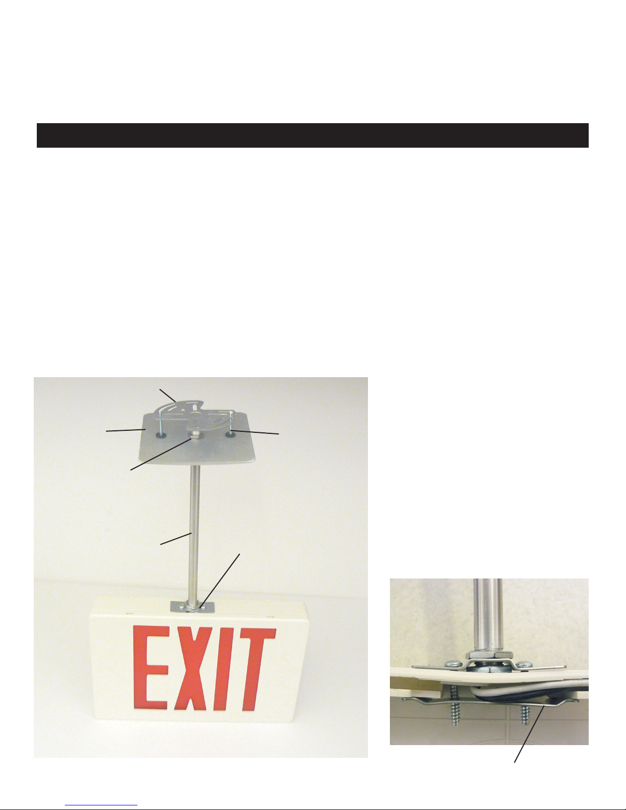
c
b
f
a
f (qty. 2)
g
h
i (qty. 2)
d (qty. 2)
e (qty. 2)
Parts Description
aPendant
bMounting Canopy
cUniversal Mounting Bracket
dScrew, 8-32 X 1 1/4"
eRetaining Washer
fPalnut
g Upper housing Bracket
hLower housing Bracket
iScrew, 8-18 x 1” PH type 25
Fig. A
page 1
Fig. B
h

Installation: Pendant Mount
Note: Installation process is the same for both the
EX and LQM exit signs, but the correct kit needs
to be used due to differences in the housing
mounting brackets.
1. Attach screws d to mounting canopy b using retainer
washers e.
2. Thread palnut f onto one end of pendant a the complete
length of the thread. Next feed upper mounting bracket g
onto same threaded end and secure with 2nd palnut f.
(See figure B for bracket orientation).
3. Thread canopy b onto opposite end of pendant a and
secure with palnut f. Palnut can be loosened to allow
turn of pendant for proper Exit orientation.
4. Make wire voltage selection and connect wires using
pushnut connections to pendant input wires inside of unit.
Route opposite end of pendant input wires (not supplied)
through housing wireway and out through the housing top
opening.
5. Route pendant input wires through pendant at lower
housing bracket h end (see Fig. B).
6. Attach pendant assembly to Exit sign using lower housing
bracket h and (2) screws i. Do not over-tighten. (see
Fig. C)
7. Attach universal mounting bracket c to 4” octagonal j-
box.
Position canopy end and make input wire connection.
8. Align canopy screws d to universal mounting bracket c
and tighten until rear side of canopy is flush with ceiling
surface.
Fig. C
Attachment to Exit Housing
Fig. D
Attachment to Mounting Canopy
(Note: J-Box bracket shown un-attached
to J-box for clarity).
page 2
 Loading...