

Page 1

Installation Instructions
FGB HIGH BAY SERIES:
READ AND FOLLOW ALL SAFETY INSTRUCTIONS!
SAVE THESE INSTRUCTIONS AND DELIVER TO OWNER AFTER INSTALLATION
IMPORTANT SAFETY INSTRUCTIONS
WARNING
To reduce the risk of death, injury or property damage from fire, electric shock, cuts, abrasions, falling parts, and
other hazards:
• Service of the equipment must be performed by qualified service personnel.
• Installation and maintenance must be performed by a person familiar with the construction and operation of this
product and any hazards involved. All applicable codes and ordinances must be followed.
• Read this document before installing, servicing, or maintaining this equipment or installing a lamp. These
instructions do not cover all installation, service, and maintenance situations. If your situation is not covered, or if
you do not understand these instructions or additional information is required, contact ACUITYBRANDS or your
local ACUITYBRANDS Distributor.
• Read and follow all warnings and instructions provided by the lamp manufacturer.
WARNING
Before installing, servicing, or maintaining this equipment, follow these general precautions.
To reduce the risk of electrocution:
• Make sure the equipment is properly grounded.
• Always de-energize the circuit and/or equipment before connecting to, disconnecting from, or servicing
the equipment.
To reduce the risk of fire:
• Keep material away that can burn from hot lamp.
• Make sure lamps are correctly installed.
• Use supply conductors with a minimum installation temperature rating as specified on equipment.
To reduce the risk of personal injury from cuts, abrasions, or falling parts:
• Wear gloves to prevent cuts or abrasions from sharp edges when removing from carton, handling and
maintaining this equipment.
• Do not use abrasive materials, glass cleaners or other solvents on reflector or lens. The se substances
may damage equipment and cause parts to eventually break and fall.
• Do not install a damaged fixture.
CAUTION: Observe lamp manufacturer’s recommendations a nd restrictions on lamp operation, including but not limited to
ballast type, burning position, replacement and cycling. Use only lamps that comply with applicable ANSI standards.
NOTICE: If lamp is marked
ACUITYBRAND assumes no responsibility for claims arising out of improper or careless installation or handling of this product.
it contains mercury. Follow disposal laws. See www.lamprecycle.org
SAVE THESE INSTRUCTIONS
Page 2
SECTION 1: INSTALLATION INSTRUCTIONS
1.1 Disconnect all power to the luminaire being worked on and remove the old luminaire from the
ceiling Inspect the ceiling for any damage. Make sure the ceiling is rated for 4X the load.
1.2 Remove the new fixture from the box and check for any damages. Handle new fixture with care.
If damaged do not use; call your local rep for replacements.
1.3 Decide on a hanging or mounting method that will work for your application. If unsure of how to
hang fixture, contact your local rep or manufacturer. Make sure the new fixture is securely
mounted to the ceiling structure.
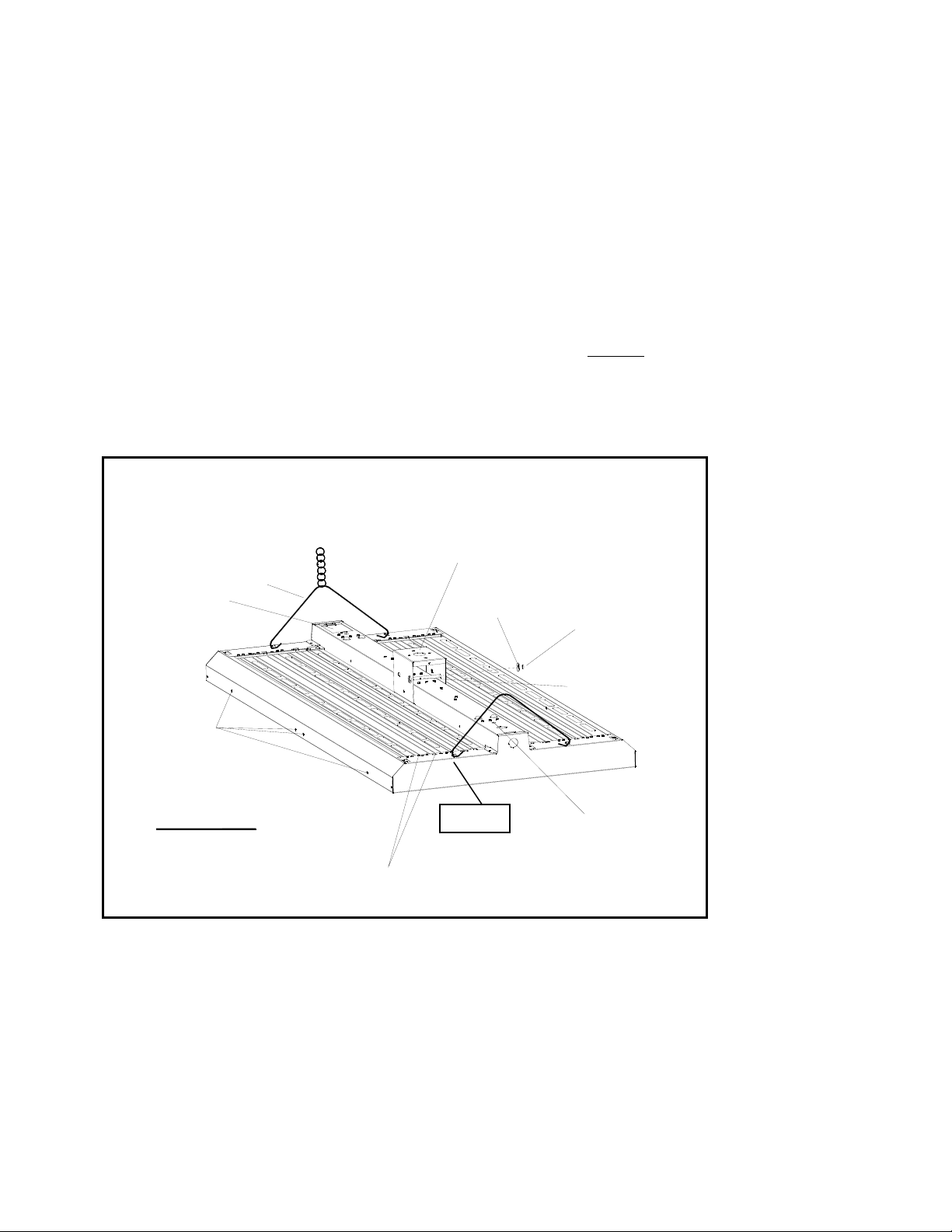
• If hanging fixture by optional mounting bracket, use the provided carriage bolt to secure the
bracket to the fixture. Do not over tighten the carriage bolt. This will deform the hanging bracket.
Make sure the bracket grip flange snaps into the groove on the fixture channel. SEE FIGURE 1.
• If hanging by chain, optional trapeze hangers can be purchased. The trapeze hanger clips into
the pre-punched loop on the luminaire end cover. Remember to crimp the trapeze hanger to
create a closed loop when done. Due to manufacturing tolerances, the loops on the end cover
might be a little lower on some units. Use a small tool to slightly increase the loop diameter if
needed in order for the trapeze wire diameter width to fit.
• If hanging by Gripple System, optional Gripple cables and hardware can be purchased. Insert the
hook connector into the 5/16” diameter holes on the back of the fixture.
• If stem mounting, use only approved stem hardware rated for 4X the load.
HANGING FEATURE
OPTION 2: .047" THICK HANGER BRACKET
(HUB OR VARIOUS SIZE MNT HOLE AVAILABLE)
OPTION 1 : T RAPEZE / CH AIN
ACCESS PLATE
NOT AVAILABLE
ON 2FT FXT
PRE PUNCH
NAIL HOLE S
FOR WIRE GUARD OR
DOOR INSTALLATION
FIGURE 1
OPTION 3: 5/16" DIA. HOLES FOR
GRIPPLE CABLE SIZE #2
WASHER
CRIMP
LOCKNUT
1/4-20 CARRIAGE BOLT
OPTION 4: 1/4-20 THREADED ROD
38" CENTER TO CENTER
ONLY AVAILABLE ON 4FT FXT
1.4 Connect line wire to new fixture wiring, black-to-black, white-to-white and green to ground.
Make sure all-new connectors and wires are UL rated (90°C or greater).
1.5 Reinstall the center reflector using the ¼” turn fasteners (if removed during hanging installation).
IMPORTANT – Do not use pliers to install fasteners. Use special fastener tool or hands. Pliers
crush fastener.
1.6 If present, remove the protective plastic liner from the reflector(s). Clean all residues and/or
fingerprints from the luminaries and reflector.
1.7 Install new lamps. Use only lamps specified on the ballast. Make sure lamps are correctly seated
in the lamp holders (sockets) before twisting.
Page 3
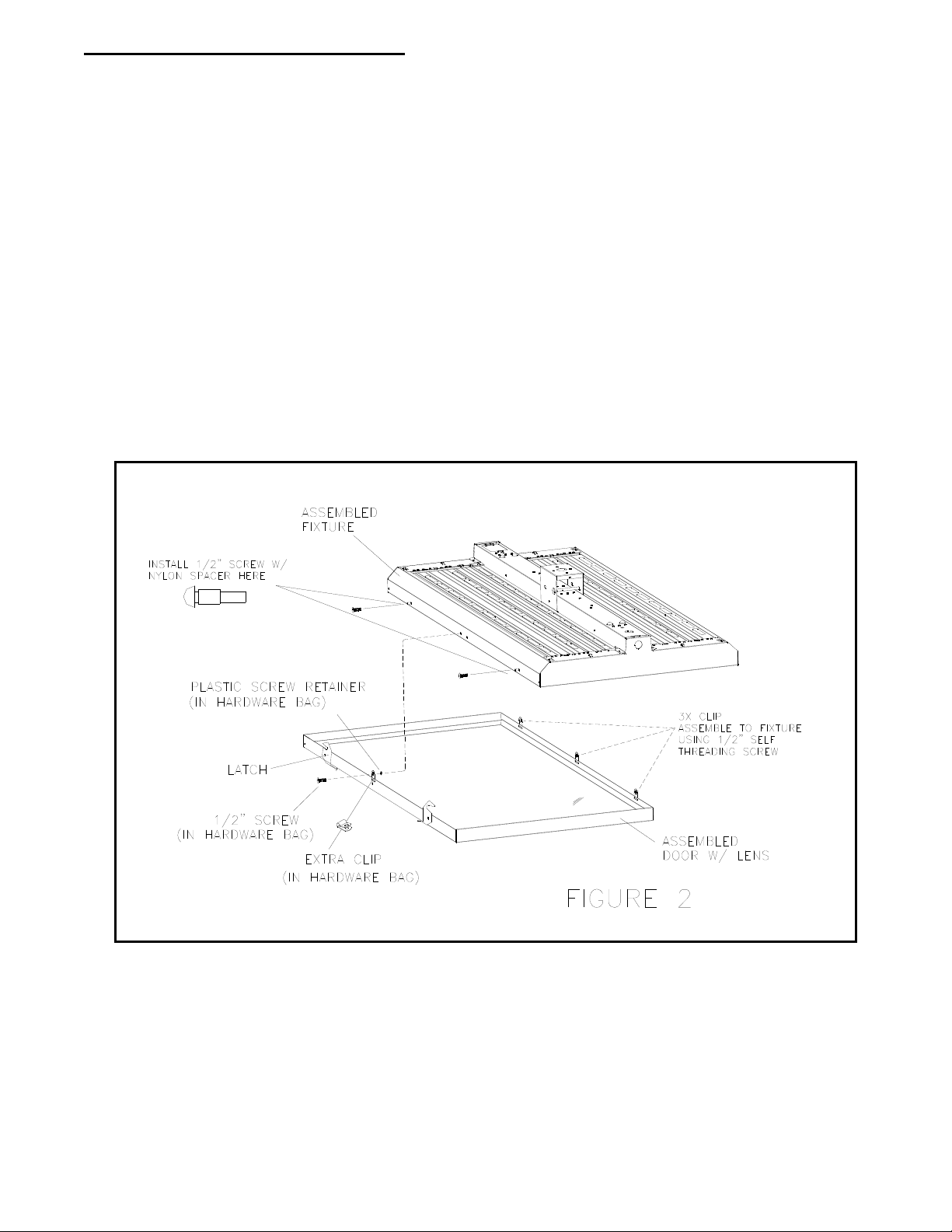
1.8 DOOR VERSION (for extra security): - Install the extra clip to the door using the provided
½” self-threading machine screw and plastic retaining washer as shown in FIGURE 2. This
should be done on the latch door side. The screw should engage the pre-punched nail
hole on the side of the fixture rail. This step is required on all high bay with door options.
SECTION 2: FIELD INSTALLED DOOR INSTRUCTIONS
2.1 Install the clips onto the door hinge rail rectangle slots (3 per side for the 2x4 door and 2 per side
for the 2x2 door). Install the door onto the fixture using the provided ½” self-threading screws.
The door should swing smoothly.
2.2 Install the nylon spacer onto the ½” self-threading machine screw. SEE FIGURE 2.
2.3 Install the screws into the pre-punched nail hole on the fixture (2 per fixture). Do not over tighten
the screws; this will deform the nylon spacer. SEE FIGURE 2.
2.4 Rotate the door to close position and rotate the latches to lock the door into position. NOTE:
make sure the latch fully engages the nylon spacer.
2.5 Install the extra clip on the latch side, center on door using the provided ½” self-threading machine
screw. The screw should engage the pre punched nail hole on the side of the fixture rail.
SEE FIGURE 2.
SECTION 3: FIELD INSTALLED WIRE GUARD INSTRUCTIONS
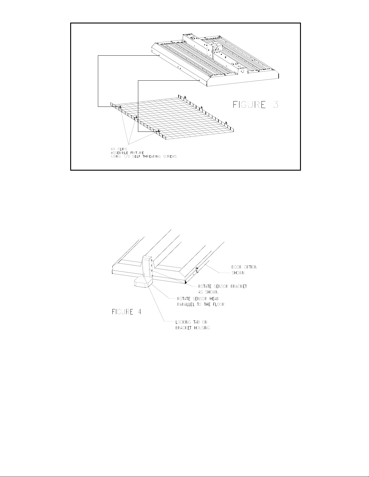
3.1 Install the clips onto the wire guard (make sure clips are oriented correctly). Test fit the first wire
guard onto the fixture to make sure the clips are installed in the correct cell. The clips should line
up with the pre-punched nail holes on the side of the fixture. Make sure the wire guard is centered
on the fixture. SEE FIGURE 3.
3.2 Mount the wire guard to the fixture using the provided ½” self-threading screws. The screws
should line up to the pre punched nail holes on the side of the fixture. DO NOT OVER TIGHTEN
SCREWS. SEE FIGURE 3.
Page 4
SECTION 4: SENSOR EQUIPPED HIGH BAY
4.1 Remove the protective covering on the sensor unit. Remove the protective wire bushing on the
end cover. This is used to protect sensor wiring during shipping.
4.2 Sensors are pre wired at the factory. Snap the sensor base into the hole on the end cover.
Make sure part is fully snapped into position.
4.3 Rotate the sensor base unit and head unit as shown in FIGURE 4.
SECTION 5: MAINTENANCE INSTRUCTIONS
5.1 Remove the lamps from the luminaire. Remove the center reflector from the luminaire. Save all hardware and store
reflectors in a safe location. Wear gloves when handling reflectors-sharp edges can cause cuts.
5.2 Remove the old ballast and install a new one in the same location. Use the same hardware from the removed
ballast(s).
5.3 Follow wiring diagram on the ballast. Use only UL recognized components and wires rated 90C or greater.
5.4 To replace the lamp holders, remove the lamp holder brackets. Install the new lamp holders into the existing location.
Follow lamp holders wiring diagram on ballast. If unsure please contact factory.
5.5 Reinstall the lamp holder brackets by sliding them into the pre formed clips on the end covers.
5.6 Reinstall the reflectors using the old hardware. Use gloves when handling reflectors, edges are sharp. IMPORTANT
– Do not use pliers to reinstall the middle reflectors camlocks. Use special fastener tool or hands. Pliers crush the
fasteners causing the camlocks to be loose.
5.7 Clean all residues and/or fingerprints from the luminaries and reflector.
5.8 Install new lamps. Use only lamps specified on the ballast. Make sure lamps are correctly seated in the lamp holders
(sockets) before twisting.
5/7/12 revised AU4325
 Loading...