

Page 1
INSTALLATION INSTRUCTIONS
UNIVERSAL STEM KIT
FOR USE WITH MOST LITHONIA EXIT SIGNS
CAUTION: For safety and proper operation, read and follow instructions carefully before installation.
IMPORTANT SAFEGUARDS
1.READ AND FOLLOW ALL
SAFETY INSTRUCTIONS
2. Before wiring to power supply, turn off electricity at fuse or
circuit breaker.
3. Disconnect A.C. power before servicing.
4. All servicing should be performed by qualified personnel.
5. Consult your local building code for approved wiring and
installation.
6. Do not use outdoors.
7. Do not mount near gas or electric heater.
8. Fixture must be grounded to avoid potential electric shock.
9. Equipment should be mounted in locations and at heights
where it will not readily be subjected to tampering by unauthorized personnel.
10. The use of accessory equipment not recommended by the
manufacturer may cause an unsafe condition.
11. Do not use this equipment for other than intended use.
SAVE THESE INSTRUCTIONS
IMPORTANT NOTE:
1. The use of a 4" octagon junction box (not supplied) is
required for mounting.
2. All exit sign electronics must be in the exit sign
housing.
Refer to product instruction sheet for wiring diagrams,
maintenance instructions, and warranty information.
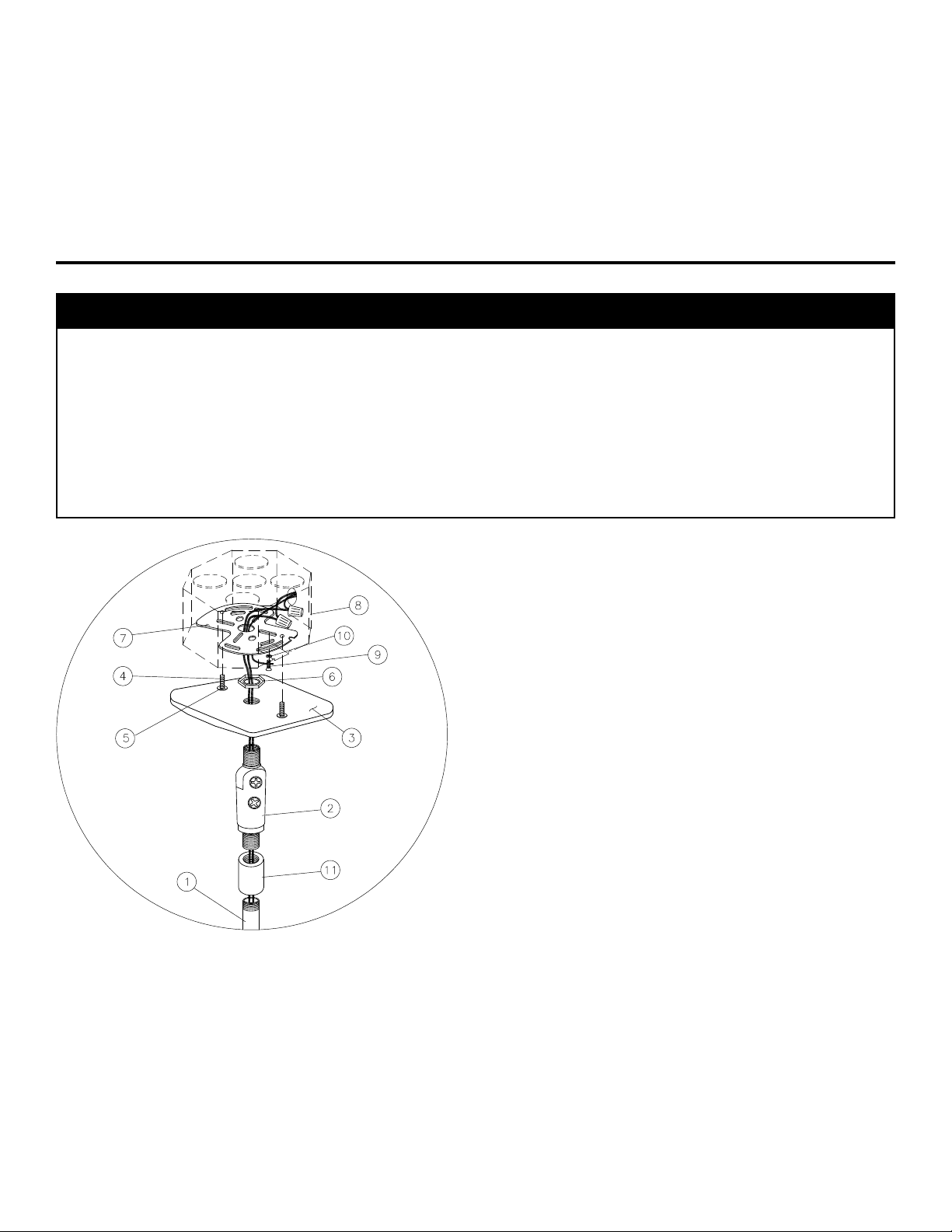
Parts Description
a Pendant
b Swivel (Fig 1)
c Mounting Canopy
d Screw, 8-32 X 1 1/4"
e Retaining Washer
f Palnut
Figure 1
Pendant Mount
to Junction Box
g Universal Mounting
Bracket
h 4" Octagon J-Box
(not supplied)
i Green Ground Screw
j Cupwasher
k Coupling
Installation: Pendant Mount
1. Attach screws d to mounting canopy c using retainer
washers e.
2. Thread swivel b into mounting canopy c. Secure swivel
to mounting canopy with palnut f. Attach threaded
pendant a into opposite end of swivel, using coupling k.
3. Position universal mounting bracket g on 4" octagon j-box
h (not provided) and fasten using screws provided with
j-box.
4. Make wirenut connections to A.C. supply lines inside 4" jbox and feed pendant wires (not provided) through center
hole in universal mounting bracket.
5. Using green ground screw i and cupwasher j, make
ground connection to universal mounting bracket g.
6. Feed pendant wires through center hole in mounting
canopy and pendant and attach mounting canopy c to
universal mounting bracket g with screws d.
Page 2
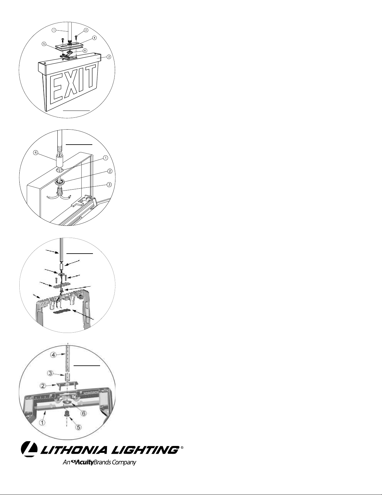
Parts Description
EM ER GE NC Y L IG HT IN G SY ST EM S
TE L: 8 00 -3 34- 86 94 Fa x: 7 70 -9 81- 81 41 www .li th on ia .co m
a Pendant
b Bracket Screws, 8-32
X 3/8"
c Panel Assembly
d Lamp Housing Bracket
e Lamp Housing Gasket
f Palnut
g End Cap Screws, 8-32
Figure 2
Figure 3
X 3/8" C'snk
h End Cap
Parts Description
a Exit Housing knockout
b Lockwasher
c Hex Nipple
d Coupling
Parts Description
a
c
e
g
Figure 4
b
d
f
h
a Pendant
b Coupling
c Washer
d Screws, 8-18 X 1"
e Upper Pendant
Bracket
f Hex Nipple
g Exit Housing
h Lower Pendant
Bracket
Parts Description
Figure 5
a Wire Cover
b Mounting Hole Cover
c Coupling
d Pendant
e Hex Nipple
f Washer
Page 2
Installation: Pendant to Precise LED (AC
only) Exit Sign (see fig. 2)
Note:
1. Thread housing bracket d onto opposite end of pendant
2. Select appropriate leads in panel assembly c and wirenut
3. Attach panel assembly c to lamp housing bracket d
4. Set exit fixture plumb to floor by adjusting the angle of
Pendant mounting requires that the polarized
connector (plug half) (see Wiring Diagram on Precise
Product Instruction sheet) be cut off approximately 3"
behind plug and the leads be stripped to approximately
5/16" for wirenut connections.
a. Slide gasket e onto threaded end of pendant and
position with housing bracket d. Secure gasket e with
palnut f.
to pendant wires (using wirenuts provided).
using screws b. Important Note: Care should be taken
to dress leads into lamp housing to leave clearance for
palnut f and pendant a when attaching panel assembly
c to lamp housing bracket d.
stem/swivel assembly and tighten screw on side of the
swivel to lock securely in place.
Installation: Pendant to Signature or Titan or
EDG Exit Sign (see fig. 3).
1. Remove center knockout a from top of exit housing.
2. Install lockwasher b onto threaded hex nipple c and
insert hex nipple through hole in top of exit housing.
3. Screw coupling d onto hex nipple c and screw one end
of stem into coupling d.
4. Set exit fixture plumb to floor by adjusting the angle of
stem/swivel assembly and tighten screw on side of the
swivel to lock securely in place.
Installation: Pendant to Quantum LHQM
Combo (see fig. 4)
1. Attach hex nipple f through upper pendant bracket e,
washer c, into coupling b. Screw coupling b assembly
onto pendant a.
2. Remove hole plug from top of housing g. Thread jumper
wires from coupling b assembly into housing g.
3. Attach lower pendant bracket h with thread cutting
screws d, capturing housing g between upper and lower
brackets.
4. Set exit fixture plumb to floor by adjusting the angle of
stem/swivel assembly, and tighten screw on side of the
swivel to lock securely in place.
Installation: Pendant to Quantum Die-Cast
LQC Exit Sign (see fig. 5)
1. Open wire cover a at inside top of exit sign.
2. Remove upper mounting hole cover b and drill 9/16” dia.
hole through center knockout. Snap mounting hole cover b
into place.
3. Screw coupling c onto pendant d. Attach hex nipple e
through washer f, and mounting hole cover b, into
coupling c.
4. Make appropriate input connections inside wire cover a.
Dress wires and close wire cover securely.
5. Set exit fixture plumb to floor by adjusting the angle of stem/
swivel assembly and tighten screw on side of the swivel to
lock securely in place.
EMCSA00704
Rev. D
 Loading...