

Lithonia Lighting LHXNY Installation Instructions Manual
INSTALLATION INSTRUCTIONS
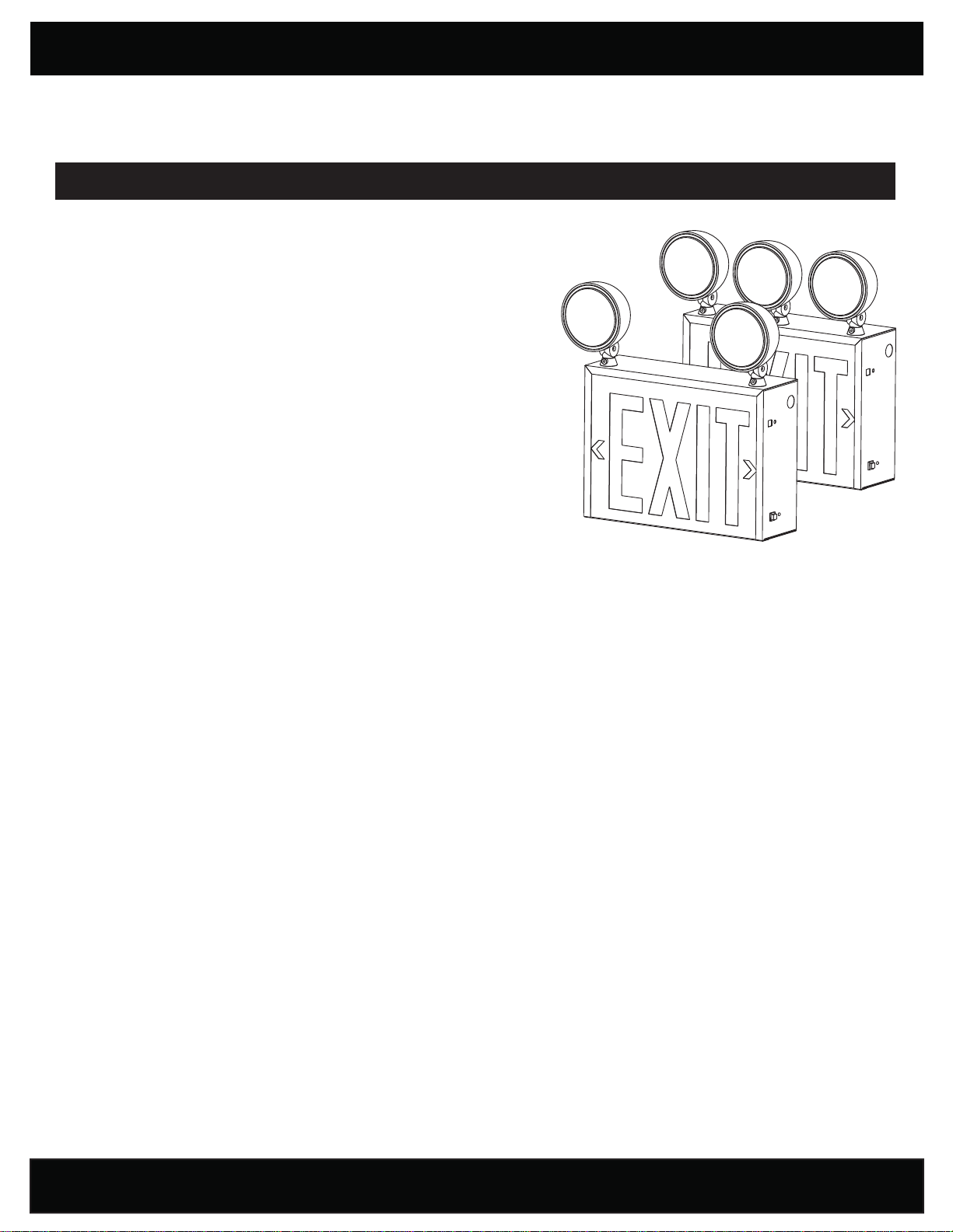
NEW YORK APPROVED STEEL EXIT/LIGHTING UNIT COMBO
LHXNY
READ AND FOLLOW ALL SAFETY INSTRUCTIONS
WARNING:
MAY RESULT IN DEATH, SERIOUS INJURY OR SIGNIFICANT PROPERTY
DAMAGE. For your protection, read and follow these warnings and instructions
carefully before installing or maintaining this equipment. These instructions
do not attempt to cover all installation and maintenance situations. If you do
not understand these instructions or additional information is required, contact
LITHONIA LIGHTING or your local LITHONIA LIGHTING distributor.
WARNING:
DISCONNECT FROM, OR SERVICE WHILE EQUIPMENT IS ENERGIZED.
WARNING: RISK OF FIRE. Lamps are hot. Keep combustible material away
from hot parts. Observe lamp manufacturer’s warnings, recommendations
and restrictions on lamp operation and maintenance. Make sure lamps are
correctly installed.
WARNING: DO NOT USE ABRASIVE MATERIALS, OR OTHER
SOLVENTS. USE OF THESE SUBSTANCES MAY DAMAGE FIXTURE,
WHICH MAY RESULT IN PERSONAL INJURY.
WARNING: RISK OF PERSONAL INJURY. This product may have sharp edges. Wear gloves to prevent cuts or abrasions when
removing from carton, handling, installing and maintaining this product.
IMPORTANT SAFEGUARDS: When using electrical equipment, basic safety precautions should always be followed, including the following:
• Before wiring to power supply, turn off electricity at fuse or circuit breaker.
• Disconnect AC power and unplug battery before servicing.
• Consult your local building code for approved wiring and installation.
• Do not use outdoors.
• Do not let power supply cord touch hot surfaces.
• Do not mount near gas or electric heater.
• Do not install a damaged fi xture.
• This product must be installed in accordance with the applicable installation codes and ordinances.
• Proper grounding is required to ensure personal safety (where applicable).
• All service shall be performed by qualifi ed personnel. This product must be installed and maintained in accordance with the
applicable installation codes by a person familiar with the construction and operation of the product and the hazards involved.
• Equipment should be mounted in locations and at heights where it will not be subjected to tampering by unauthorized personnel.
• The use of accessory equipment not recommended by the manufacturer may cause an unsafe condition.
• Do not use this equipment for anything other than its intended use.
FAILURE TO FOLLOW THESE INSTRUCTIONS AND WARNINGS
RISK OF ELECTRIC SHOCK - NEVER CONNECT TO,
CAUTION: Halogen cycle lamp(s) may be used in this fi xture. To avoid shattering, do not operate lamp in excess of rated voltage.
Protect lamp against abrasions and scratches and against liquids when lamp is operating. Dispose of lamps with care. Halogen lamps
operate at high temperatures. Do not store or place fl ammable materials near lamps.
WARRANTY Three Year: This three-year warranty covers any defect in manufacturing, provided the defect develops under normal and
proper use. This liability extends only to replacement of the defective part. Labor charges will be honored by the factory only with prior written
approval from an authorized post-sales representative.
PAGE: 1 of 2
SAVE THESE INSTRUCTIONS
and deliver to owner after installation

INSTALLATION INSTRUCTIONS
NOTE: Max mounting height is 8 ft to achieve at least 1 ft-candle of illuminance in emergency mode.
IMPORTANT:
●
When re-lamping use only lamps specifi ed by the manufacturer. Using other lamp types may result in transformer damage or cause
unsafe conditions.
● Battery in this unit may not be fully charged. After electricity is hooked up to the unit, let the battery charge up for at least 24 hours. Then
normal operation of this unit should then take effect.
INSTALLATION INSTRUCTIONS (back mount):
1. Slide out the front exit panel face plate and lens/fi lter by removing the screw on the bottom of the unit.
2. Remove internal metal refl ector plate by removing the two (2) screws.
3. Determine which mounting holes will be used to mount the fi xture to J-BOX and then punch out the proper K/Os from the K/O pattern
on the back panel of the housing.
4. There are two additional KEY HOLE slots located on the top of the unit. These holes must be used when the unit is mounted to the wall.
5. Connect AC supply wires to fi xture input wires. Black is for 120V; Red is for 277V; White is for neutral.
6. Connect the RED and BLUE leads coming from the circuit board to the battery terminals. RED lead would be connected to the positive
terminal and BLUE lead to the negative terminal.
7. Replace the internal metal refl ector and secure unit with the two (2) screws.
8. Re-insert the front EXIT panel and red lens/fi lter and secure with screw.
OPTION:
The package includes an additional lamp head. If required, this head could be mounted in between the two existing heads on the unit. This
could be done before, during or after the unit’s installation. The procedure is described in the following steps:
1. Punch out the square mounting hole on the top of the unit.
2. Mount the head securely with the included nut (FIG. A).
3. Connect the yellow and violet wires coming from the circuit board (labeled “Remote Wires”) to the yellow and violet wires on the lamp
head using wire nuts or any other prescribed method.
WARNING: Unused wires must be capped using enclosed wire nuts.
LED BOAR D
277 VOLT
120 VOLT
COMM
RED
BLACK
WHITE
+
BATTERY
TRANS F
-
RED
BLUE
CHARG ER
BOARD
BLACK
LAMP HEAD INSTALLATION
RED
VIOLET
YELLOW
VIOLET
YELLOW
VIOLET
YELLOW
BLACK
BLACK
To Remote
SWITCHAC ON
LAMP LAMP
LAMP
Star
Washer
Nut
FIG A
INSTRUCTION
One Lithonia Way, Conyers GA 30012
Phone: 800-334-8694
www.lithonia.com
Part #EMCSA00748 Rev. C
2017.06.20
PAGE: 2 of 2
 Loading...