

Lithonia Lighting ELM2 LED Installation Instructions Manual
INSTALLATION INSTRUCTIONS
ELM2 LED
CAUTION: For safety and proper operation, read and follow instructions carefully before installation.
® LED Series
Patent # US: D473,672
D483,511
D484,272
IMPORTANT SAFEGUARDS
READ AND FOLLOW ALL SAFETY INSTRUCTIONS
SAVE THESE INSTRUCTIONS AND DELIVER TO OWNER AFTER INSTALLATION
WARNING: FAILURE TO FOLLOW THESE INSTRUCTIONS AND WARNINGS MAY RESULT IN DEATH, SERIOUS INJURY OR SIGNIFI-
CANT PROPERTY DAMAGE- For your protection, read and follow these warnings and instructions carefully before installing or maintaining this
equipment. These instructions do not attempt to cover all installation and maintenance situations. If you do not understand these instructions or
additional information is required, contact Lithonia Lighting or your local Lithonia Lighting distributor.
WARNING:
WARNING: RISK OF FIRE- Lamps are hot. Keep combustible material away from hot parts. Observe lamp manufacturer’s warnings,
recommendations and restrictions on lamp operation and maintenance. Make sure lamps are correctly installed.
WARNING: DO NOT USE ABRASIVE MATERIALS OR OTHER SOLVENTS. USE OF THESE SUBSTANCES MAY DAMAGE FIXTURE,
WHICH MAY RESULT IN PERSONAL INJURY.
WARNING: RISK OF PERSONAL INJURY- This product may have sharp edges. Wear gloves to prevent cuts or abrasions when removing
from carton, handling, installing and maintaining this product (WHERE APPLICABLE).
• Before wiring to power supply, turn off electricity at fuse or circuit breaker.
• Disconnect AC power and unplug battery before servicing.
• Consult your local building code for approved wiring and installation.
• May be used outdoors under cover. (10°C- 40°C).
• Do not let power supply cord touch hot surfaces.
• Do not mount near gas or electric heater.
• Do not install a damaged fi xture.
RISK OF ELECTRIC SHOCK- NEVER CONNECT TO, DISCONNECT FROM, OR SERVICE WHILE EQUIPMENT IS ENERGIZED.
• This product must be installed in accordance with the applicable installation codes and ordinances.
• Proper grounding is required to ensure peronal safety (WHERE APPLICABLE).
• All service shall be performed by qualifi ed service personnel. This product must be installed and maintained in accordance with the applicable
installation codes by a person familiar with the construction operation of the product and the hazards involved.
• Equipment should be mounted in locations and at heights where it will not readily be subjected to tampering by unauthorized personnel.
• The use of accessory equipment not recommended by the manufacturer may cause an unsafe condition.
• Do not use this equipment for other than intended use.
PAGE: 1 of 4
SAVE THESE INSTRUCTIONS
and deliver to owner after installation
INSTALLATION INSTRUCTIONS
NOTE: This unit should be mounted ONLY through a pair of the preformed keyholes onto a 4” “OCTAGON” junction box, or
through a pair of the keyhole knockouts onto a 4” SQUARE junction box.
NOTE: The maximum mounting height for the standard model is 12.3 feet.
The maximum mounting height for the HO model is 11.0 feet.
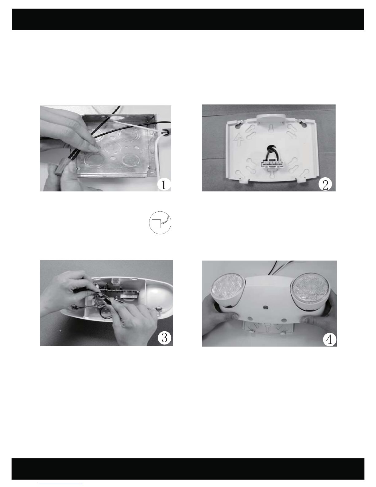
Feed the fi xture leads through the mounting plate and
make connections to AC power supply.
Use only Flexible Conduit with this
unit. Must be used with 4” j-box.
With AC power turned off, connect battery connector
leads.
CAUTION: Continuous AC power must be available
at time of installation as damage to the battery will occur
if the battery is connected to the charger board for more
than 3 days.
Dress the wires into the junction box. Secure the mounting
plate onto the junction box with a minimum of two screws.
NOTE: To ensure proper engagement of the snaps in the
mounting plate to the housing, DO NOT OVERTIGHTEN
SCREWS.
Align the holes on the bottom of the housing with the circular
snaps at the bottom of the mounting plate and push the
housing directly onto the mounting plate. (NOTE: Make
sure red battery wires are securely inside battery compartment prior to mounting housing
onto mounting plate.)
The two at the bottom, as well as the two hidden snaps at
the top should make an audible snap when fully engaged.
Apply continuous AC power and check that the test switch is
illuminated red, indicating proper function.
PAGE: 2 of 4
 Loading...