

Page 1
INST ALLATION INSTRUCTIONS
EMERGENCY FLUORESCENT BATTERYPACK
Model EI500
IMPORTANT SAFEGUARDS
READ AND FOLLOW ALL SAFETY INSTRUCTIONS
WARNING: FAILURE T O FOLLOW THESE INSTRUCTIONS AND WARNINGS MAY RESUL T IN DEATH, SERIOUS INJUR Y
OR SIGNIFICANT PROPERTY DAMAGE –
For your protection, read and follow these warnings and instructions carefully before installing or maintaining this equip-
ment. These instructions do not attempt to cover all installation and maintenance situations. If you do not understand
these instructions or additional information is required, contact Lithonia Lighting or your local Lithonia Lighting distributor.
WARNING: RISK OF ELECTRIC SHOCK – NEVER CONNECT TO, DISCONNECT FROM OR SER VICE WHILE EQUIPMENT IS ENERGIZED.
WARNING : RISK OF FIRE – Lamps are hot. Keep combustibles material away from hot parts. Observe lamp
manufacturer’s warnings, recommendations and restrictions on lamp operation and maintenance. Make sure lamps are
correctly installed.
WARNING: DO NOT USE ABRASIVE MA TERIALS, OR OTHER SOL VENTS. USE OF THESE SUBSTANCES MAY DAMAGE
FIXTURE, WHICH MA Y RESUL T IN PERSONAL INJURY .
WARNING : RISK OF PERSONAL INJURY – This product may have sharp edges. Wear gloves to prevent cuts or abrasions
when removing from carton, handling, installing and maintaining this product. (WHERE APPLICABLE)
• Before wiring to power supply, turn off electricity at fuse or circuit breaker.
• Disconnect A.C. power and unplug battery before servicing.
• Consult your local building code for approved wiring and installation.
• Do not use outdoors.
• Do not let power supply cord touch hot surfaces.
• Do not mount near gas or electric heater.
• Do not install a damaged fixture.
• This product must be installed in accordance with the applicable installation codes and ordinances.
• Proper grounding is required to ensure personal safety. (WHERE APPLICABLE)
• All service shall be performed by qualified service personnel. This product must be installed and maintained in accordance with the applicable installation codes by a person familiar with the construction and operation of the product and
the hazards involved.
• Equipment should be mounted in locations and at heights where it will not readily be subjected to tampering by unauthorized personnel.
• The use of accessory equipment not recommended by the manufacturer may cause an unsafe condition.
• Do not use this equipment for other than intended use.
SAVE THESE INSTRUCTIONS
FIELD INSTALLABLE FLUORESCENT BATTERY
PACK IS UNIVERSALLY COMPATIBLE WITH THE
BALLASTS AND OPERATING LAMP(S) IN THE
LAMP COMPATIBILITY TABLE (PAGE 3).
CAUTION:
A potential electrical shock hazard exists even
when AC power supply has been turned off.
Disconnect Battery connector before servicing
fixture. Do not remove the wire harness connector when AC power is present.
IMPORTANT NOTES:
Make sure that branch circuit feeds are derived from
a common phase for both normal lighting ballast and
Battery Pack prior to installation.
Notice: To ensure proper grounding, mount unit only
with metal cutting screws (not provided).
The Battery Pack can be used with a switched or
unswitched (night) circuit. When used with a switched
fixture it is important to note that the power to the
Battery Pack must be provided by an unswitched
circuit.
APPROXIMATE WORKING VOLTAGE
Battery Pack input: 120 OR 277V AC
Page 2
1. Drill or punch one 1/2” holes in fixture wall or
wireway cover.
2. Insert one side of test switch/pilot light c into the
hold from the back and snap in the other side. Slide
mounting clip firmly onto mounting post to secure
test switch assembly. Mark the test switch location
with the charge indicator label.
3. Connect test switch and pilot light c leads to
violet and grey leads on inverter. See wiring
diagram for proper connections.
4. Apply continuous power to Battery Pack.
5. Connect the battery connector e (brown leads)
c d
b e
a
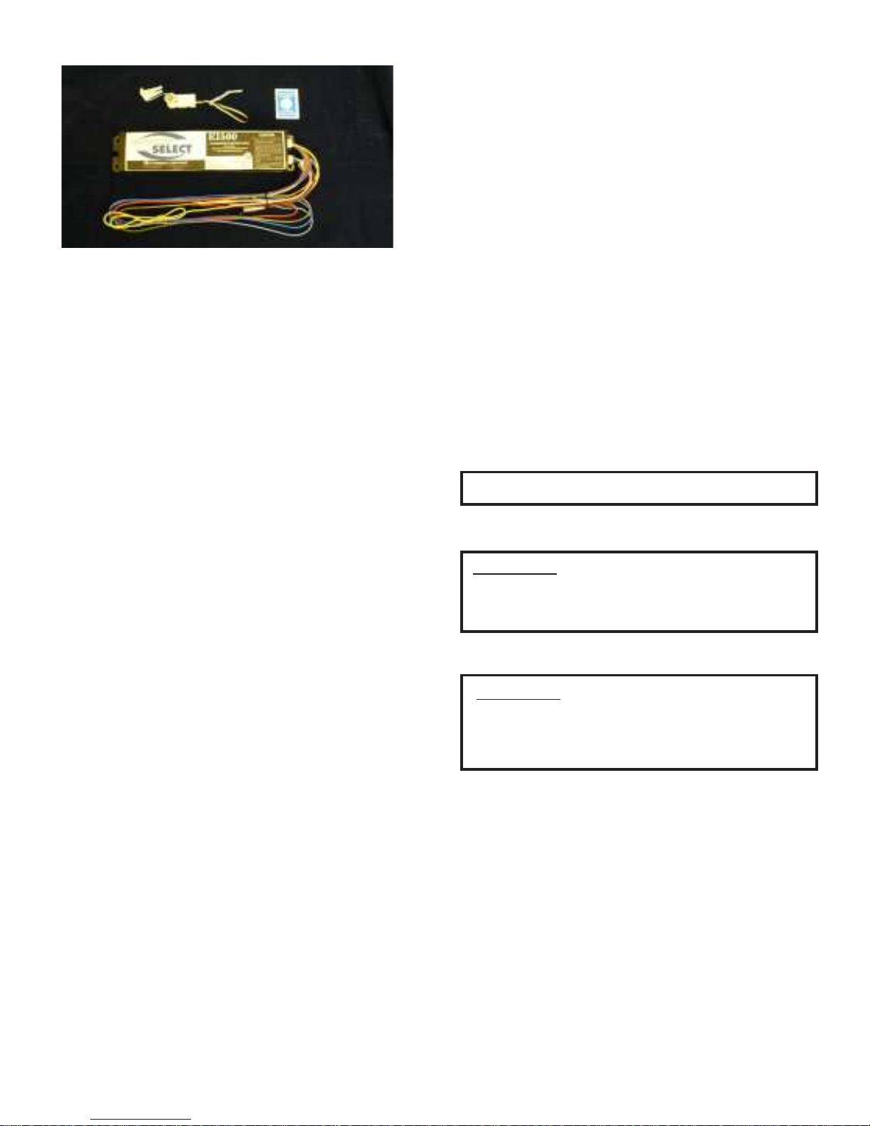
FIGURE 1
P ARTS DESCRIPTION
a HOUSING
b MOUNTING HOLES or SLOTS
c TEST SWITCH & PILOT LIGHT
d CHARGE INDICA T OR LABEL
e BA TTERY CONNECT OR
INSTALLATION
1. Turn off AC Power. Inspect Battery Pack and make sure
the Battery Connector e is disconnected. If still
connected, disconnect before installation.
2. Position unit in fixture wireway and fasten securely
through keyed slots or Mounting Holes or Slots b . If
necessary, drill holes and mount with metal cutting
screws (not provided).
3. Refer to appropriate wiring diagram. Connect unit to
ballast and lamp(s) and A.C. power leads as indicated in
appropriate wiring diagram.
INSPECTION AND MAINTENANCE
NOTE:
as local codes require, or at least quarterly to insure that all
components are operational. Perform all test required by local
codes.
1. Check equipment rating to be sure that fixture will receive
2. Be sure pilot light is on. If pilot light does not operate,
3. Press test switch. The pilot light c should be off. One
NOTE: Allow battery to charge 24 hours before initial testing
and 72 hours to fully charge battery.
NOTE: Battery packs are not field serviceable units.
Emergency lighting systems should be tested as often
proper line voltage.
check to see that:
A. Pilot Light Connector and test switch c are con-
nected.
B. AC power is on.
C. Voltage on branch circuit to Battery Pack is rated
at line voltage (120V or 277V). If no line voltage can be
measured, locate problem in branch circuit and correct.
fluorescent lamp should be operating at a reduced light
output.
CAUTION:
Damage to battery will occur if Battery connection is made
for a prolonged period of time without AC power provided.
TEST SWITCH/PILOT LIGHT (TS/PL)
INSTALLATION
CAUTION:
Do not locate Test Switch/Pilot Light c or route cable within
1” of fixture lamps.
NOTE: If pilot light is not visible outside the fixture lens, there
is a charge indicator label d located in pre-pack that should
be placed on the flat side of the lens directly below the test
switch and pilot light to identify it as an emergency fixture.
CAUTION:
Connecting the Battery Connector e also connects the
battery to the inverter circuit which can result in high
voltage being present between the output leads.
Page 2
Page 3
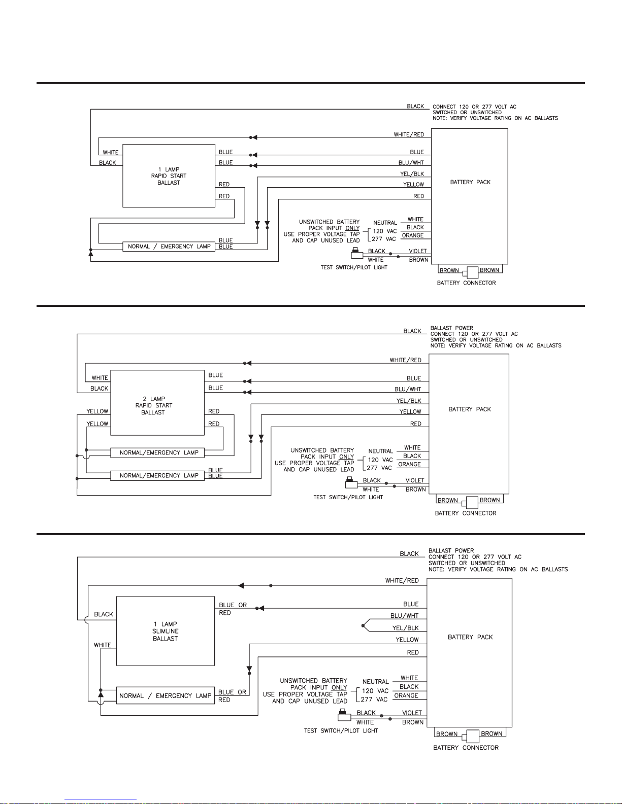
WIRING DIAGRAMS
IMPORTANT NOTES: Before connecting TS/PL connector or wiring unit to fixture, refer to INSTALLATION PROCEDURE
and IMPORTANT SAFEGUARDS f or safety information and mounting procedures.
ONE LAMP RAPID START BALLAST
FIGURE A
TWO LAMP RAPID START BALLAST
ONE LAMP INSTANT START SLIMLINE BALLAST
FIGURE B
FIGURE C
Page 3
Page 4

TWO LAMP LEAD/LAG INSTANT START SLIMLINE BALLAST
FIGURE D
TWO LAMP SERIES LEAD BALLAST
TWO LAMP INSTANT START BALLAST
FIGURE E
FIGURE F
Page 4
Page 5

THREE LAMP RAPID START BALLAST
FIGURE G
THREE LAMP INSTANT START BALLAST
FIGURE H
ONE LAMP WITHOUT AC BALLAST
FIGURE I
Page 5
Page 6

ONE LAMP INSTANT START BALLAST
FIGURE J
ONE LAMP CIRCLINE BALLAST
FOUR LAMP INSTANT START ELECTRONIC BALLAST
FIGURE K
FIGURE L
Page 6
Page 7

TWO LAMP SERIES SEQUENCE INSTANT START BALLAST
FIGURE M
FOUR LAMP RAPID START BALLAST
ONE-YEAR WARRANTY
This fixture is guaranteed to perform for a period of one year from date of invoice. Our guarantee covers any
defect in manufacturing, provided the defect develops under normal and proper use. This liability does not
include lamps, and extends only to repair or replacement of the defective part and labor charges for correction
of the defect by repair or replacement. These labor charges will be paid by Lithonia Lighting only with prior
written authority has been granted by our Post Sales department.
FIGURE N
WARRANTY
Part no. EMCSA00742
REV C
Page 7
Page 8

Page 8
 Loading...