

Page 1
READ THESE INSTRUCTIONS AND
SAVE THEM FOR FUTURE USE
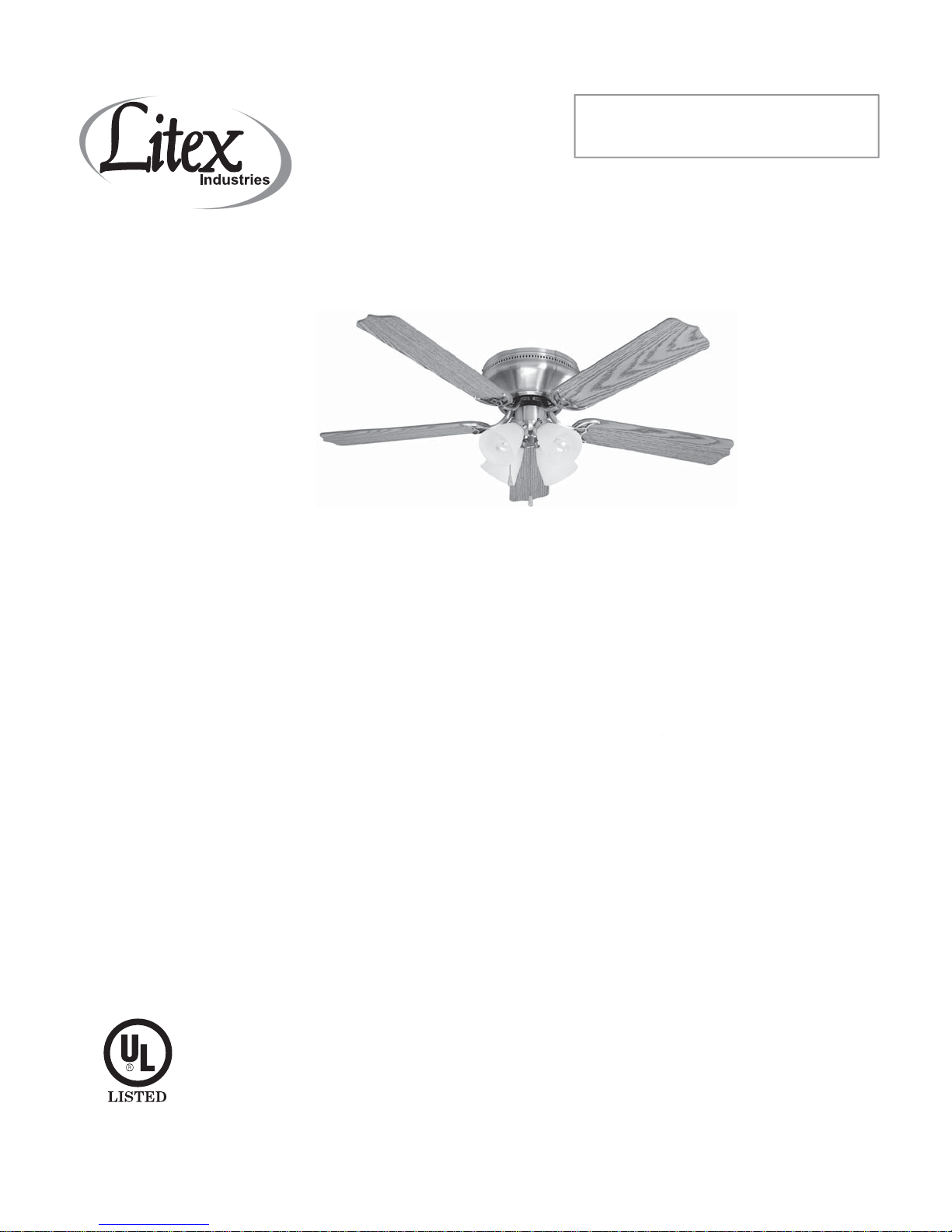
Installation Guide
For models:
BRC52BNK5C
BRC52ORB5C
Table of Contents:
Safety Tips. pg. 1
Unpacking Your Fan. pg. 2
Parts Inventory. pg. 2
Installation Preparation. pg. 3
Hanging Bracket Installation. pg. 3
Preparation for Wiring. pg. 4
Wiring. pg. 4
Fan Assembly. pg. 5
Motor Housing Assembly. pg. 5
Blade Assembly. pg. 6
Light Kit Assembly. pgs. 6 - 7
Testing Your Fan. pg. 7
E124404
net fan weight: 16.53 lb. (7.5 kg)
Troubleshooting. pg. 8
Parts Replacement. pg. 8
Warranty. pg. 8
PRINTED IN CHINA
Page 2

SAFETY TIPS.
WARNING: To reduce the risk of electrical shock, turn off the electricity to the fan at the main fuse box or
circuit panel before you begin the fan installation or before servicing the fan or installing accessories.
1. Read all instructions and safety information carefully before installing your fan and save these
instructions.
CAUTION: To avoid personal injury, the use of gloves may be necessary while handling fan parts with sharp
edges.
2. Make sure all electrical connections comply with Local Codes or Ordinances and the National
Electrical Code. If you are unfamiliar with electrical wiring or if the house/building wires are
different colors than those referred to in the instructions, please use a qualified electrician.
3. Make sure you have a location selected for your fan that allows clear space for the blades to rotate,
and at least seven (7) feet (2.13 meters) of clearance between the floor and the fan blade tips. The
fan should be mounted at least thirty (30) inches (76 centimeters) from walls or other upright
structures.
4. The outlet box and ceiling support joist used must be securely mounted, and capable of supporting
at least 35 pounds (16 kilograms). The box must be supported directly by the building structure.
Use only UL listed outlet boxes marked "FOR FAN SUPPORT."
WARNING: To reduce the risk of fire, electrical shock, or personal injury, mount to the outlet box marked
"Acceptable for Fan Support," and use the mounting screws provided with the outlet box. Most outlet
boxes commonly used for the support of lighting fixtures are not acceptable for fan support and may need
to be replaced. Consult a qualified electrician if in doubt.
WARNING: To reduce the risk of fire, electrical shock, or personal injury, wire connectors provided with this
fan are designed to accept only one 12 gauge house wire and two lead wires from the fan. If your house
wire is larger than 12 gauge or there is more than one house wire to connect to the two fan lead wires,
consult an electrician for the proper size wire connectors to use.
5. Electrical diagrams are for reference only. Light kits that are not packed with the fan must be UL listed
and marked suitable for use with the model fan you are installing. Switches must be UL general use
switches. Refer to the instructions packaged with the light kits and switches for proper assembly.
6. After installation is complete, check that all connections are absolutely secure.
7. After making electrical connections, spliced conductors should be turned upward and pushed
carefully up into the outlet box. The wires should be spread apart with the grounded conductor
and the equipment-grounding conductor on opposite sides of the outlet box.
WARNING: To reduce the risk of electrical shock and fire, do not use this fan with any variable (rheostat)
wall control.
8. Do not operate the reverse switch until the fan has come to a complete stop.
9. Do not insert anything between the fan blades while they are rotating.
WARNING: To reduce the risk of personal injury, do not bend the blade arms during assembly or after
installation. Do not insert objects into the path of the blades.
WARNING: To avoid personal injury or damage to the fan and other items, be cautious when working
around or cleaning the fan.
10. Do not use water or detergents when cleaning the fan or fan blades. A dry dust cloth or lightly
dampened cloth will be suitable for most cleaning.
WARNING: To reduce the risk of personal injury, use only parts provided with this fan. The use of parts
OTHER than those provided with this fan will void the warranty.
NOTE: The important safety precautions and instructions appearing in the manual are not meant to cover
all possible conditions and situations that may occur. It must be understood that common sense and
caution are necessary factors in the installation and operation of this fan.
page 1
Page 3
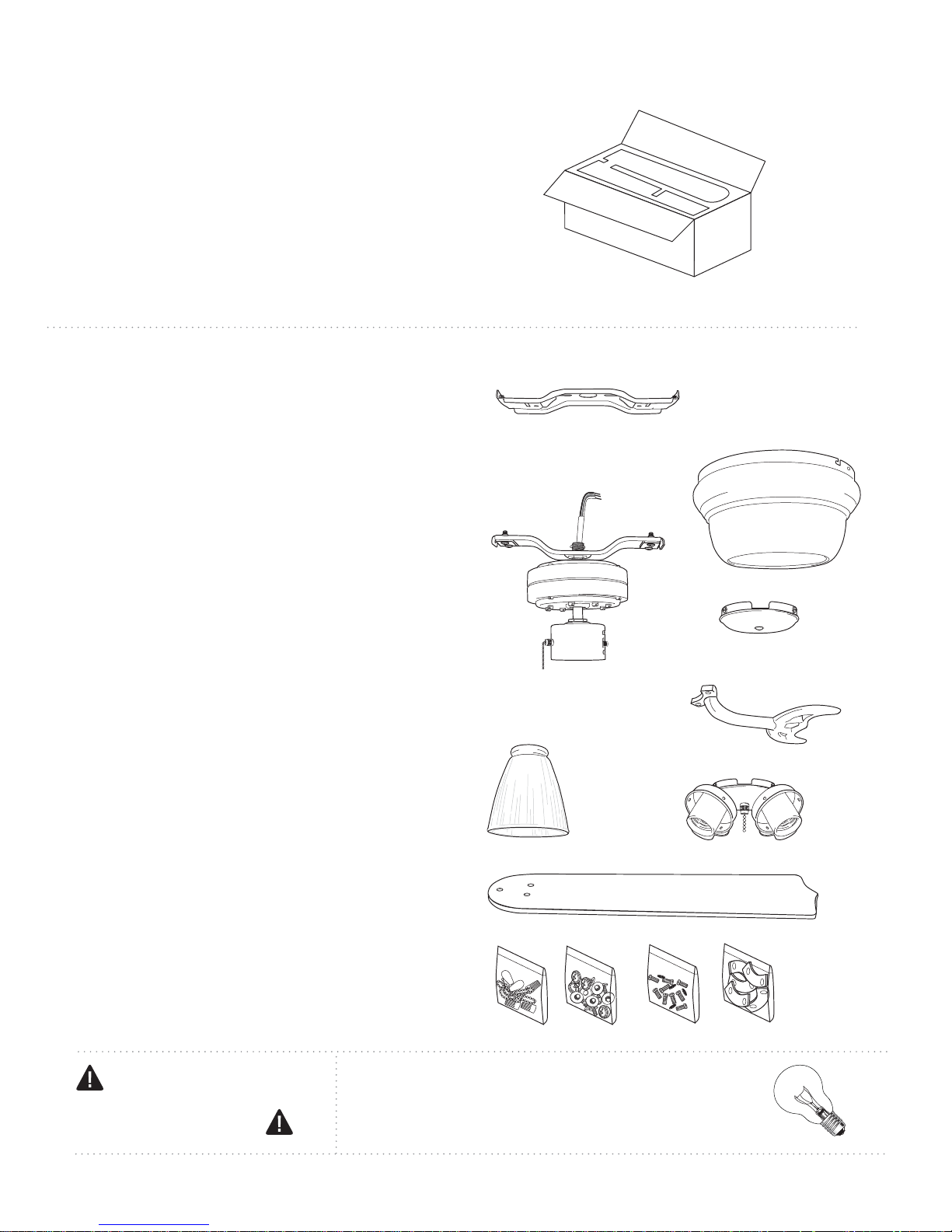
1. Unpacking Your Fan.
Carefully open the packaging. Remove items
from Styrofoam inserts. Remove motor housing
and place on carpet or Styrofoam to avoid
damage to finish. Do not discard fan carton or
Styrofoam inserts should this fan need to be
returned for repairs.
Check against parts inventory that all parts have
been included.
2. Parts Inventory.
a. hanging bracket. 1 piece
a
b. motor housing. 1 piece
c. motor assembly. 1 piece
d. switch housing cap. 1 piece
e. blade arm. 5 pieces
f. glass shade. 4 pieces
g. light kit fitter. 1 piece
h. blade. 5 pieces
i. hardware packs
b
c
d
e
f
g
h
IMPORTANT REMINDER: You must
use the parts provided with this fan for
proper installation and safety.
i
required bulbs:
4 x 60 watt max. candelabra base bulbs
(sold separately)
page 2
Page 4
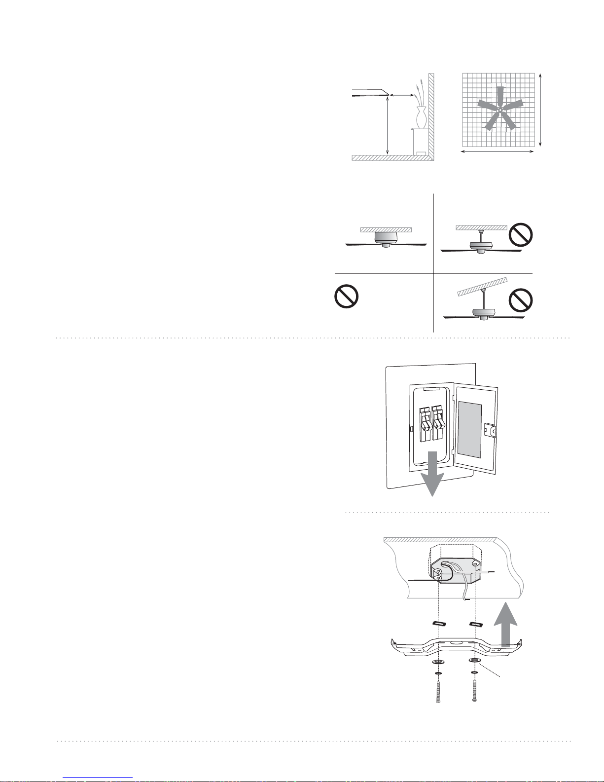
3. Installation Preparation.
To prevent personal injury and damage, ensure
that the hanging location allows the blades a
clearance of 7ft. (2.13m) from the floor and 30in.
(76cm) from any wall or obstruction.
This fan is suitable for room sizes up to 400
square feet (37.2 square meters).
blade edge
7 feet
(2.13m)
30
inches
(76cm)
12ft. - 20ft.
(3.66m - 6.1m)
12ft. - 20ft.
(3.66m - 6.1m)
This fan can only be mounted as a flushmount
on a regular ceiling. Downrod installations are
not available for this fan.
Installation requires these tools:
Phillips screwdriver, flat-head screwdriver,
adjustable pliers or wrench, stepladder, wire
cutters, and rated electrical tape.
4. Hanging Bracket Installation.
Turn off circuit breakers to current fixture from
breaker panel and be sure operating light switch
is turned to the OFF position.
WARNING: Failure to disconnect power supply
prior to installation may result in serious injury.
Remove existing fixture.
WARNING: When using an existing outlet box, be
sure the box is securely attached to the building
structure and can support the full weight of the fan.
Ensure it is clearly marked "Suitable for Fan
Support." If not, it must be replaced with an
approved outlet box. Failure to do so can result in
serious injury.
flushmount
installation
CANNOT be
installed on
angled or
vaulted ceilings
downrod
installation
ON
ON
OFF
OFF
Install hanging bracket to outlet box using
original screws, spring washers and flat washers
provided with new or original outlet box.* Install
rubber cushions (if not already pre-attached to
hanging bracket) between outlet box and
hanging bracket to reduce vibration of metal to
metal surfaces. Arrange electrical wiring to one
side of the hanging bracket.
*Note: It is very important that you use the proper
hardware when installing the hanging bracket as
this will support the fan.
page 3
rubber cushions
hanging
bracket
spring washers
outlet box screws
flat washers
Page 5
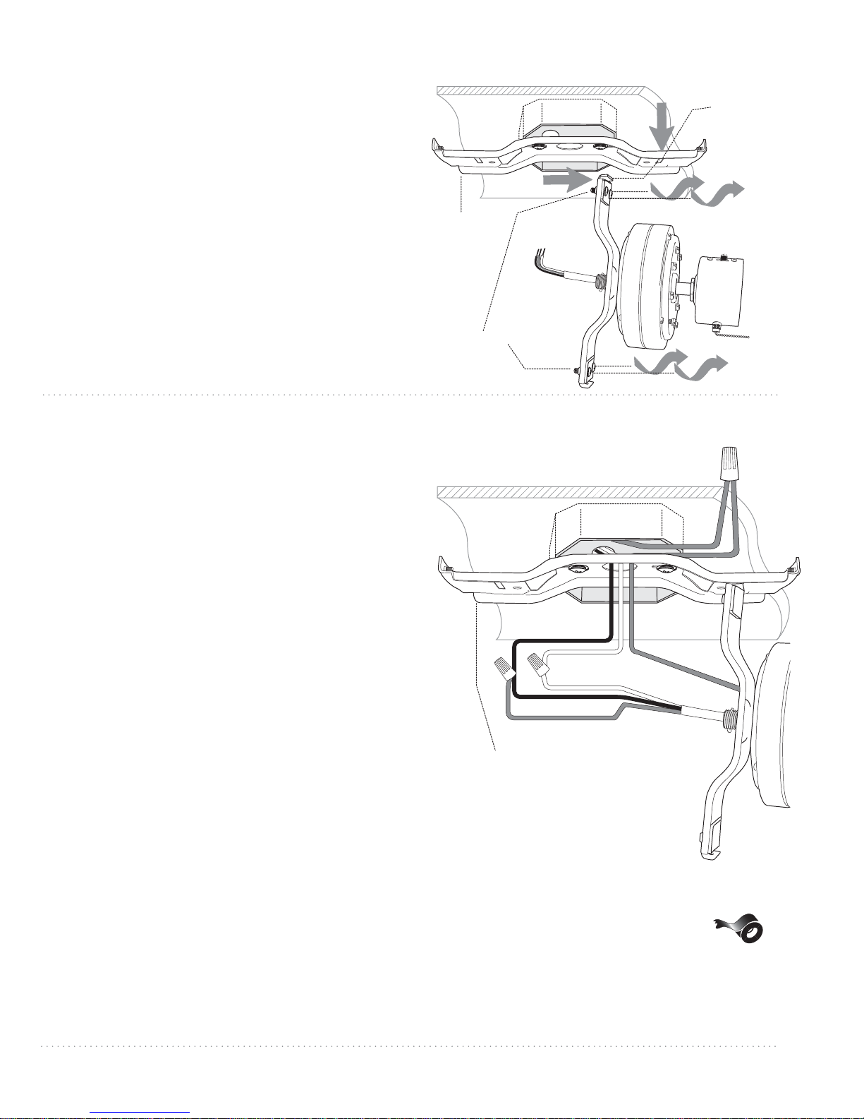
5. Preparation for Wiring.
Remove 4 motor mounting screws and washers
from underside of motor assembly. Leave rubber
cushions in place. Lift motor assembly to
hanging bracket and place one end of motor
assembly in hanging bracket slot. This will allow
motor assembly to hang out of the way while
wiring.
Tip: Seek the help of another person to hold the
stepladder in place and to lift the fan up to you
once you are set on the ladder.
Continue to "Wiring" section for wiring diagram.
6. Wiring.
hanging
bracket
motor
mounting
screws
hanging
bracket slot
motor assembly
NOTE: See instructions above (Section 5) in order to
temporarily hang fan on hanging bracket during
wiring.
Important: Be sure outlet box is properly grounded or
that a ground wire (GREEN or Bare) is present.
Make sure all electrical connections comply with Local
Codes or Ordinances and the National Electrical Code.
If you are unfamiliar with electrical wiring or if the
house/building wires are different colors than those
referred to in the instructions below, please use a
qualified electrician.
When fan is secured in place on the hanging
bracket, electrical wiring can be made as follows:
Connect BLACK and BLUE wire from fan to BLACK
wire from ceiling with wire connector provided.
Connect WHITE wire from fan to WHITE wire from
ceiling with wire connector provided.
Connect all GROUND (GREEN) wires from fan
together to BARE/GREEN wire from ceiling with
wire connector provided.
BLUE
hanging
bracket
GROUND (GREEN OR BARE) GREEN
BLACK
WHITE
WHITE
BLACK
GREEN
motor assembly
If you intend to control the fan light with a separate
light switch, connect BLUE wire from fan to the
BLACK supply from the independent switch.
* Wrap each wire connector separately with
electrical tape as an extra safety measure.
*
page 4
Page 6
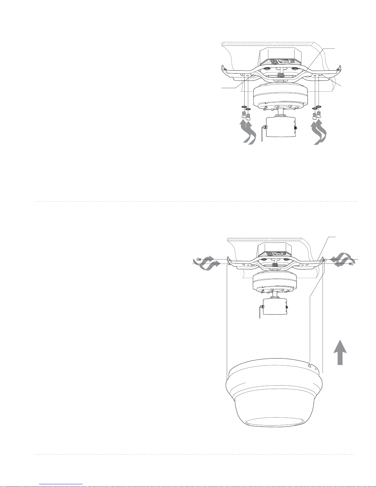
7. Fan Assembly.
Remove motor assembly from temporary
hanging slot in hanging bracket. Carefully push
wiring and wire connector into outlet box. Slide
one end of motor assembly through one of the
openings in the hanging bracket. Lift the other
end and slide through opposite opening. Align
holes on motor assembly with holes on
underside of hanging bracket. Secure motor
assembly to hanging bracket with washers and
motor mounting screws that were previously
removed (Section 5, page 4).
hanging
bracket
opening
motor
mounting
screws
hanging
bracket
opening
slot
motor
mounting
screws
motor assembly
8. Motor Housing Assembly.
Temporarily hold motor housing up to hanging
bracket to determine which 2 screws align with
slotted holes on top rim of motor housing. Put
motor housing down and partially loosen the 2
screws in the hanging bracket that correspond
to slotted holes in motor housing. Remove the
other 2 screws from the hanging bracket.
Raise motor housing to hanging bracket,
allowing slotted holes in motor housing to align
with loosened screws in hanging bracket. Twist
motor housing to lock. Re-install the 2 screws
that were removed and then tighten all screws to
secure motor housing.
motor
housing
screws
hanging
bracket
motor
housing
screws
motor
housing
page 5
Page 7
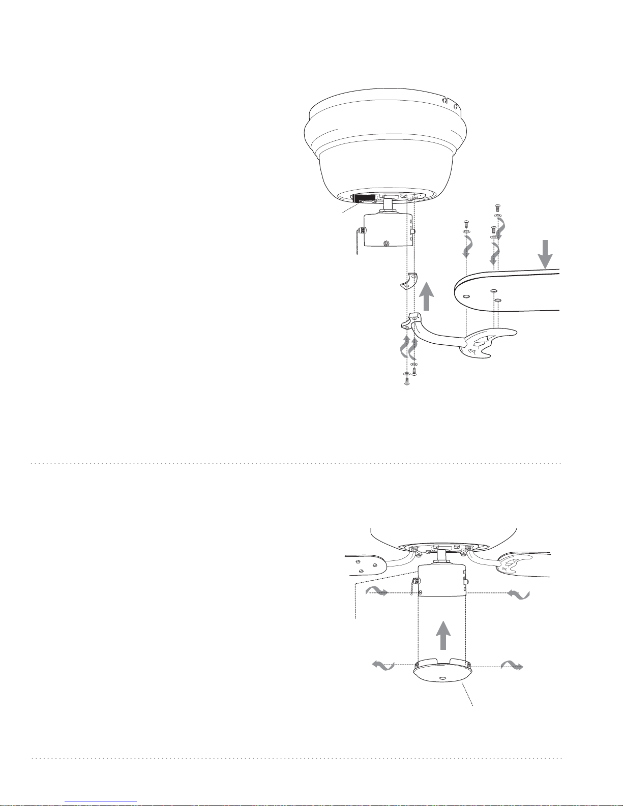
9. Blade Assembly.
Time Saver: Washers for blade screws can be set
on each blade screw prior to installing blades.
Locate 15 blade attachment screws and washers
provided in hardware pack. Hold one blade arm
up to blade and align holes. Insert 3 blade
attachment screws (along with washers) with
fingers first and then tighten screws securely
with a Phillips screwdriver. Repeat for the
remaining blades.
Remove blade arm screws and lock washers
from fan motor and set aside. Then, if applicable,
remove plastic motor locks and discard. Install
long fiber washers (provided in hardware pack)
between motor and blade arm to reduce
vibration of metal to metal surfaces. Align blade
arm holes with motor screw holes and attach
blade arm with blade arm screws and lock
washers. Before securing screws permanently,
repeat procedure with remaining blade arms.
Secure all screws completely after installing all
blade arms.
plastic
motor
lock
fiber washer
lock washers
motor housing
blade attachment
screws and washers
blade
blade arm
blade arm screws
Note: Tighten blade arm screws twice a year.
10. Light Kit Assembly (Optional).
If you wish to use your fan WITH the light kit,
please follow instructions starting on the
following page.
If you wish to use your fan WITHOUT the light
kit, remove 3 screws from switch housing cap.
Align holes in switch housing cap with holes in
switch housing. Attach switch housing cap to
switch housing with screws that were just
removed. Securely tighten all screws. Please
proceed to Section 11 on the following page to
complete installation WITHOUT the light kit.
["Light Kit Assembly" continued on next
page.]
motor housing
switch
housing
switch housing cap
page 6
Page 8
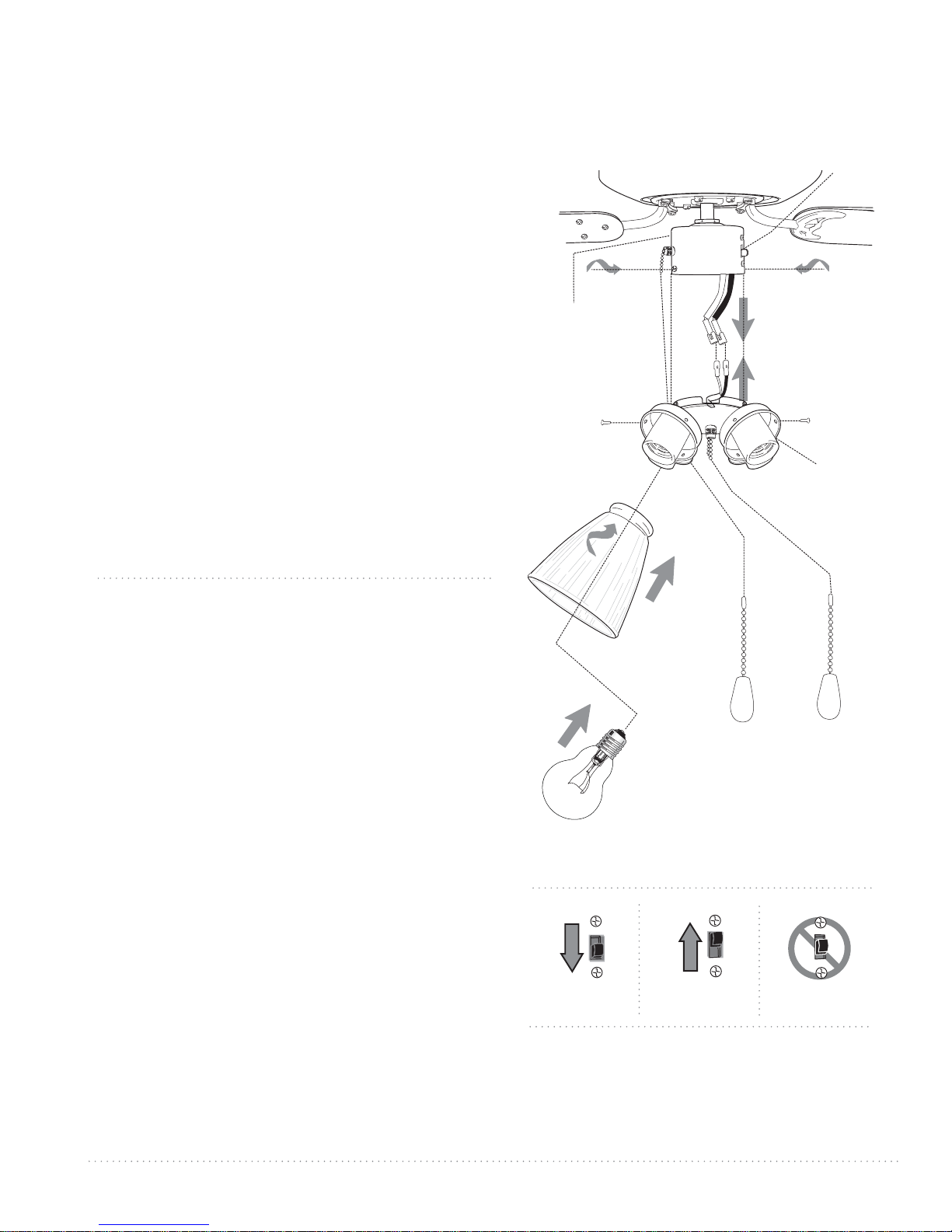
10. Light Kit Assembly (Optional). (cont.)
Remove 3 screws from light kit fitter. Locate BLUE and
WHITE wires in the switch housing labeled FOR LIGHT.
Remove and discard cardboard label and plastic that
hold these 2 wires together.
Connect WHITE wire from switch housing to WHITE
wire from light kit fitter. Connect BLUE wire from
switch housing to BLACK wire from light kit fitter. Be
sure that molex connections snap together securely.
Align holes in light kit fitter with holes in switch
housing. Attach light kit fitter with 3 screws that were
previously removed. Securely tighten all screws.
Attach glass shades to light kit fitter with thumb
screws provided in one of the hardware packs. Do not
overtighten thumb screw as glass may crack or break.
Install 4 candelabra base 60 watt max. bulbs (sold
separately).
Important: When replacing bulbs, please allow bulb(s)
and glass shade(s) to cool down before touching.
11. Testing Your Fan.
switch
housing
thumb
screw
motor housing
glass
shade
reverse
switch
molex
connections
thumb screw
light kit fitter
It is recommended that you test fan before finalizing
installation. Restore power from circuit box and wall
switch (if applicable). Test fan speeds with the pull
chain directly opposite the reverse switch. Start at the
OFF position (no blade movement). First pull will set
the fan to HI. Second pull will set the fan to MEDIUM.
Third pull will set the fan to LOW. Fourth pull will
re-set the fan to OFF setting. Test light kit with the
pull chain in the middle. (Refer to diagram 1.) If fan
and/or light do (does) not function, please refer to
"Troubleshooting" section to solve any issues before
contacting Customer Service.
Turn fan completely off before moving the reverse
switch. Set reverse switch to recirculate air depending
on the season:
- DOWN position in summer (diagram 2)
- UP position in winter (diagram 3)
A ceiling fan will allow you to raise your thermostat
setting in summer and lower your thermostat setting
in winter without feeling a difference in your comfort.
Important: Reverse switch must be set either
completely UP or completely DOWN for fan to
function. If the reverse switch is set in the middle
position (diagram 4), fan will not operate.
Attach pull chains extensions provided or custom pull
chain extensions (sold separately) to light and fan pull
chains.
pull chain
extensions
bulb
diagram 1
diagram 2 diagram 3 diagram 4
page 7
Page 9
Troubleshooting.
Problem: Fan fails to operate.
Solutions:
1. Check wall switch to fan.
2. Verify that reverse switch is set completely in
either direction.
3. Check to be sure fan is wired properly.
Problem: Light kit (optional) not lighting.
Solutions:
1. Check wall switch to fan.
2. Check that bulbs are installed correctly.
3. Check to be sure wires in outlet box are wired
properly.
Problem: Fan operates but lights fail (if
applicable).
Solutions:
1. Check that bulbs are installed correctly.
2. Check to be sure wires in outlet box are wired
properly.
3. Verify that molex connections in switch
housing are connected properly.
4. Replace defective bulbs with same type of
bulb.
Warranty.
LITEX 15-YEAR LIMITED WARRANTY:
LITEX INDUSTRIES, LTD. warrants this fan to the original
household purchaser for indoor use under the following
provisions:
1-YEAR WARRANTY: LITEX INDUSTRIES, LTD. will replace or
repair any fan which has faulty performance due to a
defect in material or workmanship. Contact Litex Customer
Service at 1-800-527-1292 to arrange for return of fan.
Return fan, shipping prepaid, to Litex Industries, Ltd. We will
repair or ship you a replacement fan, and we will pay the
return shipping cost.
5-YEAR WARRANTY: LITEX INDUSTRIES, LTD. will repair or
replace, at no charge to the original purchaser, any fan
motor that fails to operate satisfactorily when failure
results from normal use.
RETURN FAN MOTOR ONLY, shipping prepaid, to Litex
Industries. We will repair or ship purchaser a replacement
motor and Litex will pay the return shipping cost.
6 to 15-YEAR WARRANTY: LITEX INDUSTRIES, LTD. will repair
the fan, at no charge to the original purchaser for labor
only, if the fan motor fails to operate satisfactorily when
failure results from normal use. Parts used in the repair will
be billed to the purchaser at prevailing prices at time of
repair.
The purchaser shall be responsible for all costs incurred
in the removal, reinstallation and shipping of the product
for repairs.
This warranty does not apply when damage from
mechanical, physical, electrical or water abuse results in
causing the malfunction. Deterioration of finishes or other
parts due to time or exposure to salt air is specifically
exempted under this warranty.
Neither Litex Industries nor the manufacturer will
assume any liability resulting from improper installation or
use of this product. In no case shall the company be liable
for any consequential damages for breach of this, or any
other warranty expressed or implied whatsoever. This
limitation as to consequential damages shall not apply in
states where prohibited.
Parts Replacement.
For parts and information, please refer to
"Parts Inventory" on page 2.
Litex Customer Support:
1-800-527-1292
page 8
 Loading...