

Page 1
Installation
Instruc tions
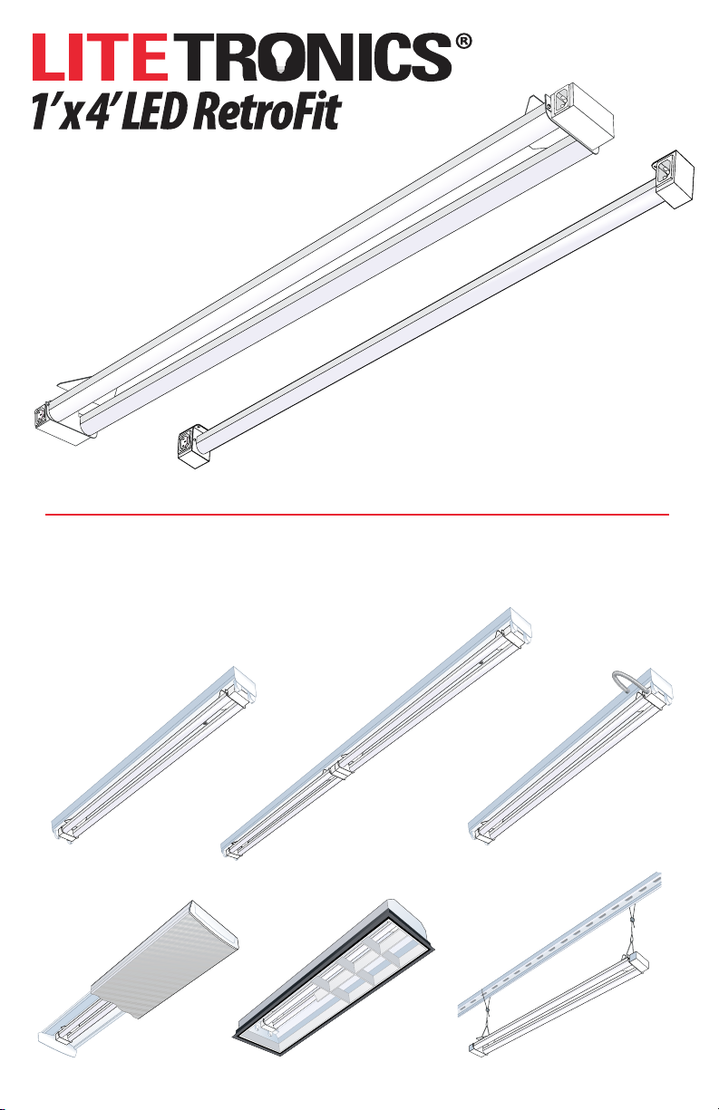
Ordering Code:
RF16UQT1XXC
RF32UQT1XXC
RF32UHT1XX
RF45UQT1XXC
RF45UHT1XX
BEFORE INSTALLATION OF THE FOLLOWING:
PLEASE READ THESE INSTRUCTIONS
4’ STRIP
FIXTURES
WRAP
FIXTURES
8’ STRIP
FIXTURES
TROFFER
FIXTURES
HARDWIRE
4’ STRIP
FIXTURES
STANDALONE
Page 2
INTRODUCTION & TABLE OF CONTENTS
Congratulations on the purchase of your 1x4 Retrot. It is usable for a range of installations. Some of the
most popular ones are included here.
Section 1- 4’ OR 8’ STRIP FIXTURE INSTALL 5
Section 2- HARDWIRE STRIP FIXTURE INSTALL 10
Section 3- TROFFER OR WRAP INSTALL 15
Section 4- STANDALONE USE 19
SAFETY INSTRUCTIONS AND WARNINGS
CRITICAL SAFETY INSTRUCTIONS: Installation should only be conducted by a qualied electrician in accordance with NEC and any relevant
local building codes.
LED RETROFIT WARNINGS: Risk of re or electric shock. LED RetroFit kit installation requires knowledge of luminaires electrical system. If not
qualied, do not attempt installation. Contact a qualied electrician. Luminaire wiring and electrical parts may be damaged when drilling for installation
of LED RetroFit kit. Check for enclosed wiring and components. Do not make or alter any open holes in the enclosure of wiring or electrical components
during kit installation. If Installing 4’ or 8’ strip xture insure width is greater or equal to 2”.
WARNING: Risk of re or electric shock. Install this kit only in luminaires that have the construction features and dimensions shown in the photo
graphs and/or drawings and where the input rating of the retrot kit does not exceed the input rating of the luminaire. Only those open holdes indicated
in the photographs and/or drawings may be made or altered as a result of kit installation. Do not leave any other open holes in an enclosure of wiring or
electrical components.
To prevent wiring damage or abrasion, do not expose wiring to edges of sheet metal or other sharp objects.
This LED RetroFit Kit and Junction Box Cover shall only be installed into a UL/CUL listed luminaire with a steel enclosure. DO NOT INSTALL THIS
RETROFIT KIT INTO LUMINAIRES WITH NON-FERROUS METAL OR POLYMERIC ENCLOSURES
Do not use with dimmers.
DISCONNECT SAFETY INSTRUCTIONS:
WARNING - This is a current rated device. Use in applications involving amperage beyond its rating can be dangerous and cause electrical res. See
note on this page for allowable current and voltage levels and do not exceed those levels.
DANGER - NEVER remove wires from product as contact with electricity can cause serious injury or death. Shut off power at the circuit breaker or
remove fuse when installing this product.
SAFETY NOTICE - Improperly installed electrical wiring can be dangerous and cause electrical res. This product must be used in accordance with
the current rating and wire sizes listed.
COPPER to COPPER ONLY. Do not use on Aluminum. Temperature rating: 105° C (221° F) maximum. Flame Rated UL94V-0.
This product is intended for use in a UL/C-UL listed Fluorescent Recessed or surface-mounted luminaire, Type IC or Non-IC, with the dimensions
specied.
-
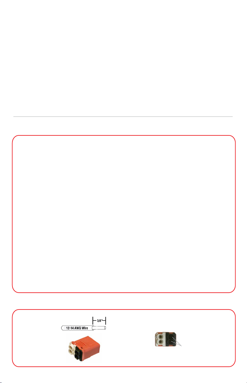
INCLUDED CN-02 CONNECTOR FOR RETROFIT POWER
Line Side (4 ports)
Neutral
2
Hot
Page 3
TOOLS AND MATERIALS FOR INSTALLATIONS
1312
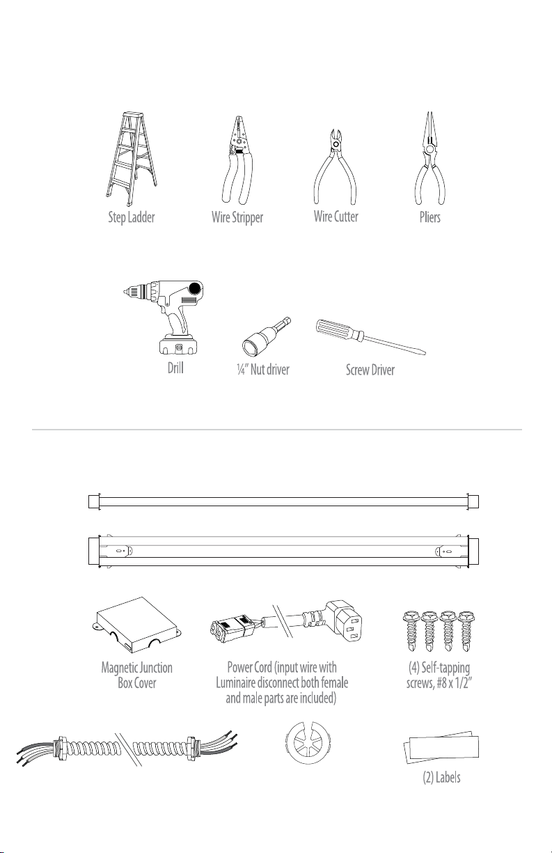
What comes in the box:
(with RF32UHT1XX
and RF45UHT1XX Only)
1x4 LED RetroFit- 1 Tube
or
1x4 LED RetroFit- 2 Tube
Split Snap BushingConduit with 14AWG Wire
3
Page 4
1X4 ACCESSORIES
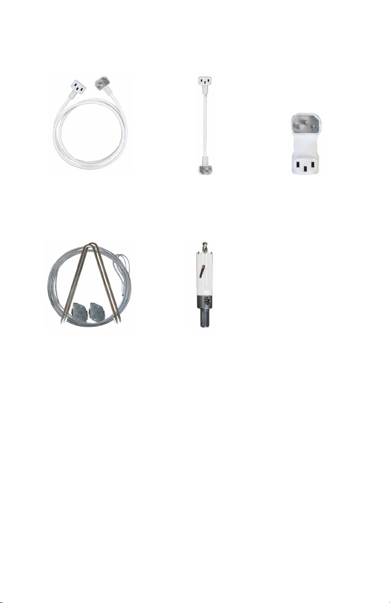
Not included but available for purchase
Power Cords
4’ Lamp to lamp extension cable
(RFAC-4FT)
Tools & Kits
Wire cable accessories
for stand alone installations
(RFAXPVL5)
8” Lamp to lamp extension cable
(RFAC-8IN)
20mm bi-metal hole saw
(RFAHS-20)
Direct dual connector
(RFAC)
4
Page 5
Section 1
RF16UQT1XXC, RF32UQT1XXC, RF45UQT1XXC
4’ & 8’ STRIP FIXTURE INSTALL
Before After
1x4 Strip Fixture with T8 Tubes 1x4 Strip Fixture with LED Retrot
1. Retrot must be installed to a grounded luminaire.
2. 1x4 strip install does not require the use of a junction box.
3. Ballast cover should be mechanically secured to physically support the Retrot.
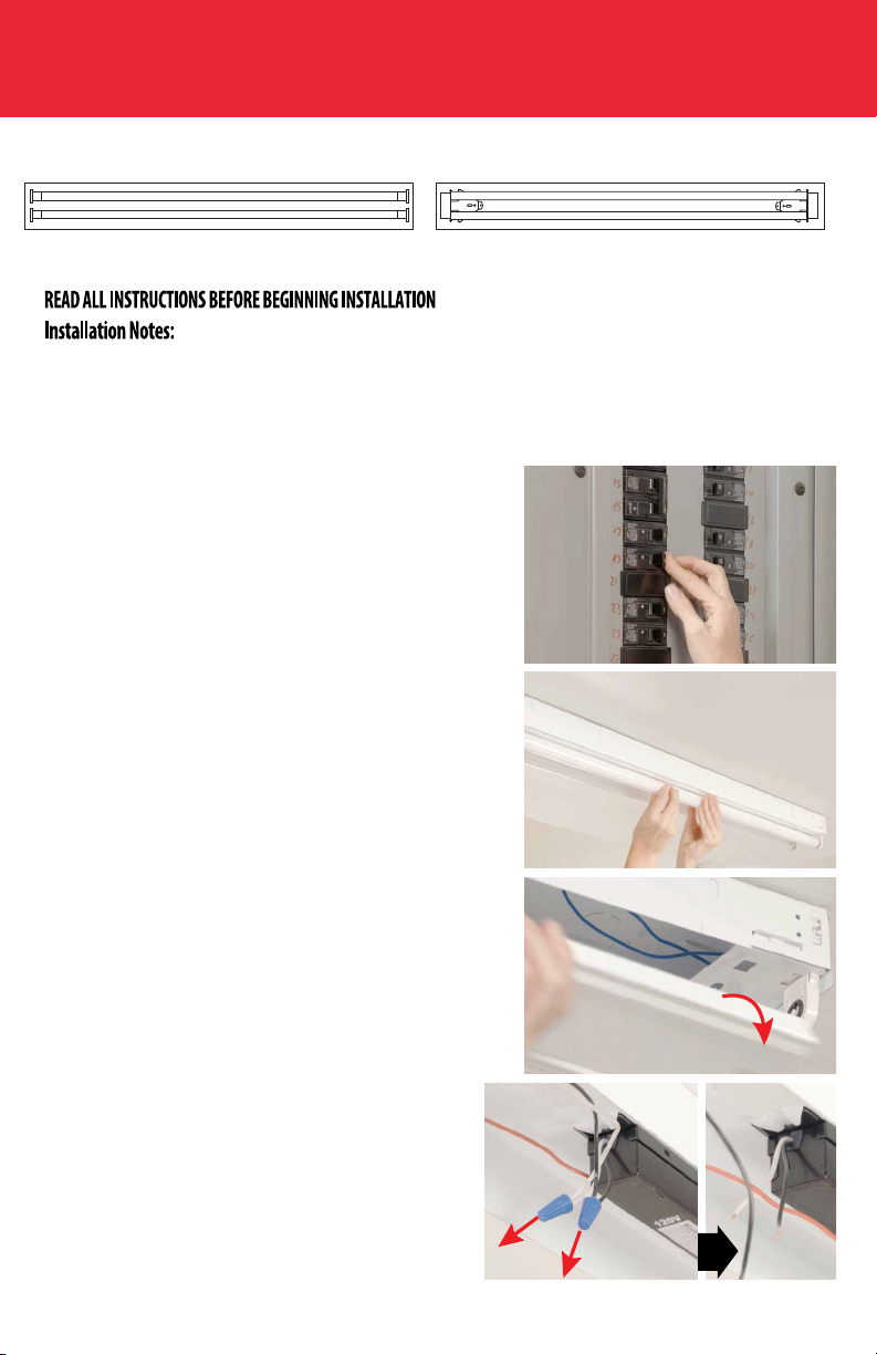
1. Turn o the power to the xture from the circuit breaker.
2. Remove the existing uorescent tubes. Recycle according to
EPA guidelines (EPA.Gov).
3. Open the xture cover (belly pan) to expose the ballast and
set it aside.
4. Disconnect the existing input and output ballast leads
close to the ballast enclosure and remove the leads (black
and white wires). Lampholders may remain in place but the
leads to the lampholders should be cut at the lamp holder
and at the ballast.
5
Page 6
RF16UQT1XXC, RF32UQT1XXC, RF45UQT1XXC
4’ & 8’ STRIP FIXTURE INSTALL
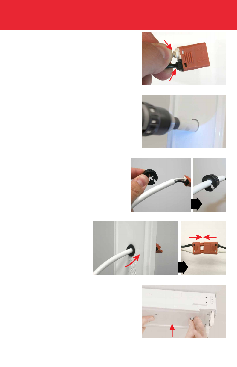
5. Connect incoming branch power leads to the included female
disconnect by pushing the wires into the corresponding color
coded black and white holes in back of connector.
6. Punch hole through side knockout of strip xture or drill a
hole through the center of the cover (set aside in step 3) near the
incoming branch power wires with 20mm bi-metal hole saw (sold
separately ordering code RFAHS-20).
7. Clip the snap bushing onto the included power cord.
8. Insert the connector and power
cord into knock out or drilled hole. Fix
bushing to panel hole. Reconnect the
male and female halves of the Luminaire
disconnect.
9. Reax the xture cover (belly pan) .
6
Page 7
RF16UQT1XXC, RF32UQT1XXC, RF45UQT1XXC
4’ & 8’ STRIP FIXTURE INSTALL
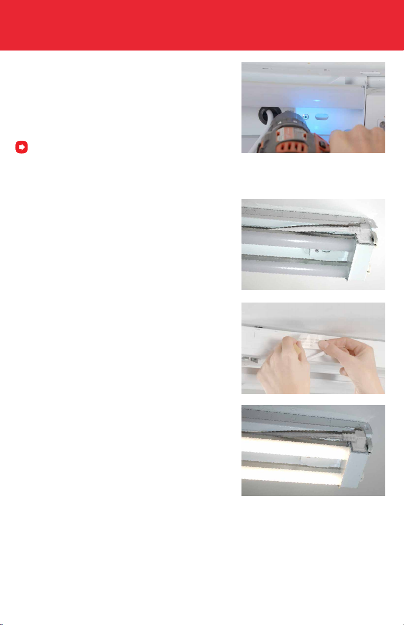
10. Attach the RetroFit to the xture cover using the rare earth
magnets. Thread power cord between the two tubes of the LED
RetroFit. Position the LED RetroFit to preferred alignment. Secure
to the xture with 2 of the included self-tapping screws.
Route and position Retrot wiring within luminaire enclosure
away from mounting hole where screws will be inserted.
11. Plug the power cord connector into the RetroFit power socket.
12. Apply both included labels to the xture.
13. Restore the power and you’re done!
7
Page 8
HOW TO USE TWO 1’X4’ RETROFITS TO CREATE 8’ STRIP
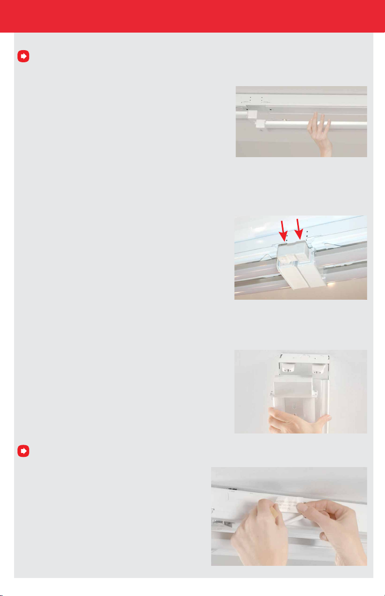
For 8’ install. Do not restore power until you complete steps 1a-1e below.
1a. Place and align the second 1’ x 4’ LED RetroFit with the C14
socket as close to the rst LED Retrot as needed to allow the use of
RFAC dual connector (or cable). The magnets will hold it in position.
1b. Push the RFAC dual connector into the sockets to connect
both LED RetroFits together.
1c. Align the second xture and secure with the 2 included
self-tapping screws.
Unused branch circuits supplying interconnected retrot luminaires should be properly terminated.
1d. Apply both included labels to the xture.
8
Page 9
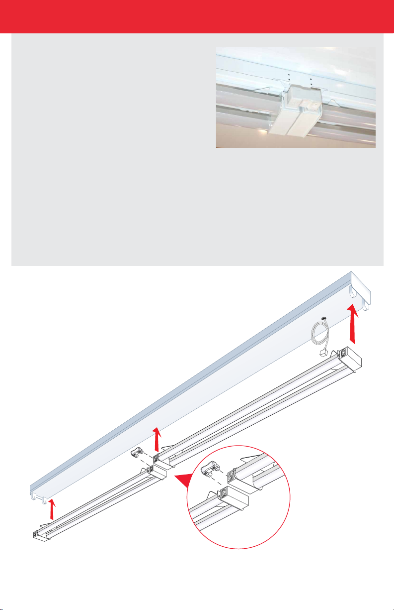
HOW TO USE TWO 1’X4’ RETROFITS TO CREATE 8’ STRIP
1e. Restore the power and you’re done! You have
combined two 1’x4’ Retrots into an 8’ xture.
Our 1x4’s can be assembled into long chains o one power source depending on Retrot wattage. Connect retrots
when aligned together using the dual connector (RFAC).Connect retrots together when up to 8” apart using 8in
lamp to lamp extension cable (RFAC-8IN). Connect retrots together when 8”- 4’ apart using 4ft lamp to lamp
extension cable (RFAC-4FT). Cables shown on page 4.
Maximum number of units by Watts
16W = 36 Retrots
32W = 18 Retrots
45W = 12 Retrots
9
Page 10
Section 2
RF32UHT1XX, RF45UHT1XX, RF32UQT1XXC AND RF45UQT1XXC
HARDWIRE STRIP FIXTURE INSTALL
Before After
1x4 Hardwire Strip Fixture with T8 Tubes 1x4 Hardwire Strip Fixture with LED Retrot
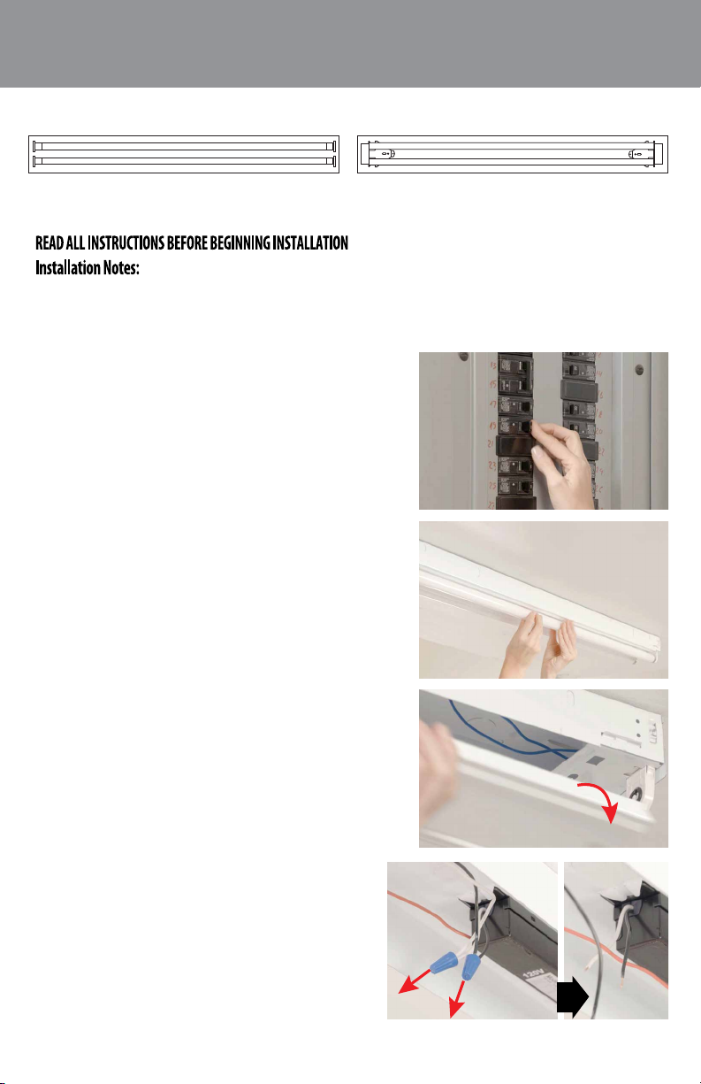
1. Retrot must be installed to a grounded luminaire.
2. Hardwire install does not use a junction box.
3. Ballast cover should be mechanically secured to physically support the Retrot.
1. Turn o power to the xture from the circuit breaker.
2. Remove existing uorescent tubes. Recycle according to
EPA guidelines (EPA.Gov).
3. Remove xture cover (belly pan) to expose the ballast and set
it aside.
4. Disconnect ballast wires from the incoming electrical
lines. (Black and white wires).
10
Page 11
RF32UHT1XX, RF45UHT1XX, RF32UQT1XXC AND RF45UQT1XXC
HARDWIRE STRIP FIXTURE INSTALL
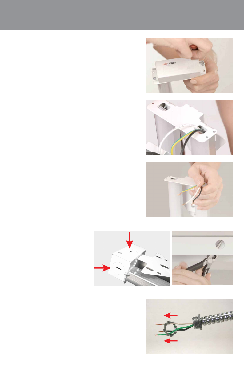
5. On the LED RetroFit RF32UHT1XX and RF45UHT1XX open the
end cover with the Litetronics logo by removing both screws.
6. Once open, the internal black, white and green/yellow wires
to the LED tubes are visible.
7. Strip the black, white and green/yellow wires coming from
the tubes of the LED Retrot to expose about ¼” of wire.
8. Remove chosen knockout from the
RetroFit end cover and make the xture
hole to connect the conduit.
9. Remove the nut from the conduit.
End Cover Fixture Hole
11
Page 12
RF32UHT1XX, RF45UHT1XX, RF32UQT1XXC AND RF45UQT1XXC
HARDWIRE STRIP FIXTURE INSTALL
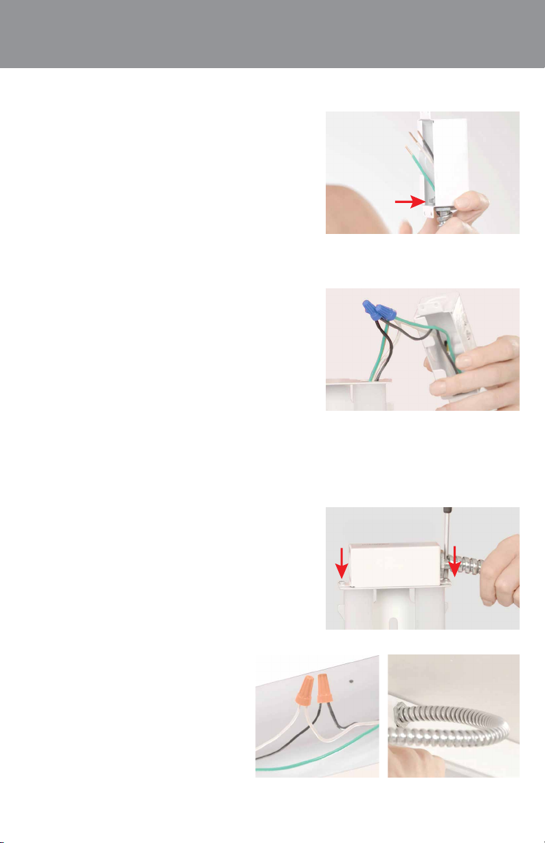
10. Insert the conduit wires (black, white & green) through
the hole of end cover. Place the conduit nuts over the three
conduit wires inside cover. After that, push conduit end into
knockout hole and secure with conduit nut.
11. Connect conduit wires to LED RetroFit using wire nuts.
-Black to black
-White to white
-Green to green/yellow.
12. Replace end cover, and secure it with the two screws.
13. The wires on other end of the conduit go into
the xture hole. Remove the conduit nut. Push
the three wires into the xture hole, then through
the conduit nut, and secure. Connect conduit
wires to incoming electrical lines inside xture.
Connect black to black, white to white with wire
nuts. Then connect the green/yellow wire to
ground screw of strip.
12
Page 13
RF32UHT1XX, RF45UHT1XX, RF32UQT1XXC AND RF45UQT1XXC
HARDWIRE STRIP FIXTURE INSTALL
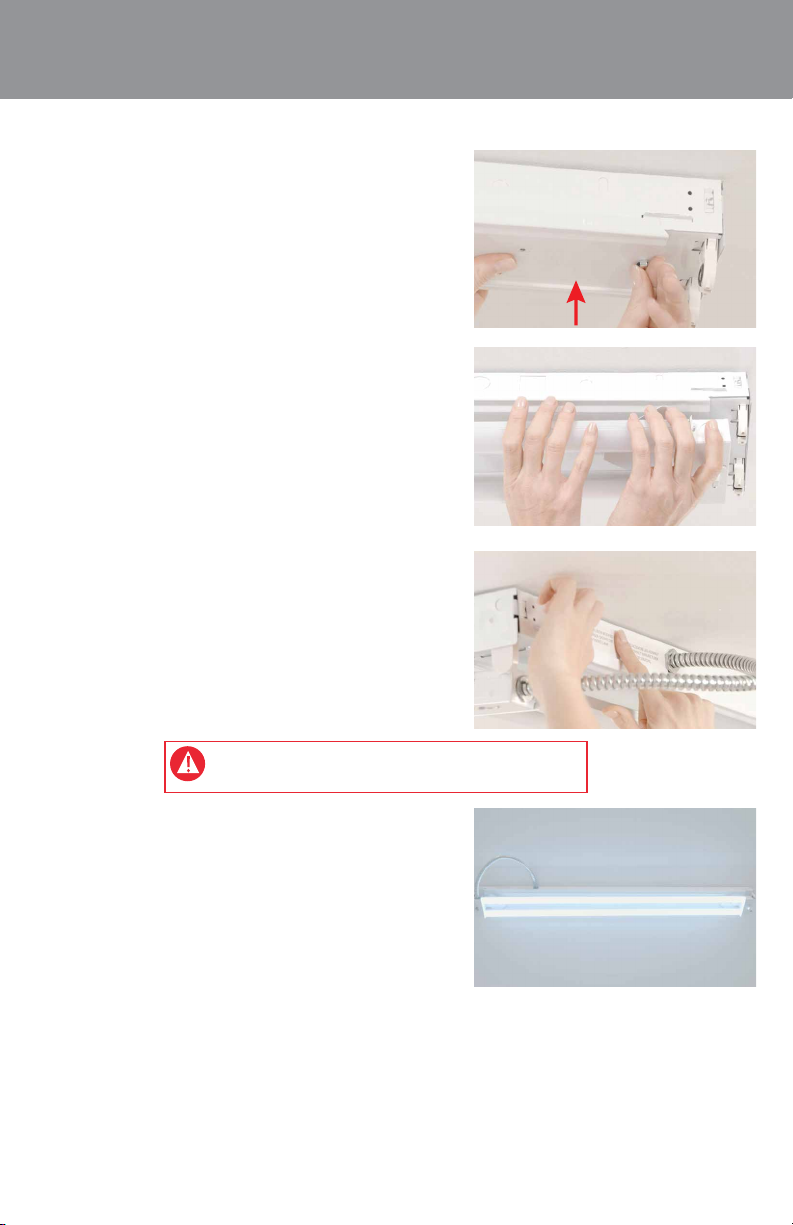
14. Reax xture cover (belly pan).
15. Attach xture belly pan to your RetroFit with the rare earth
magnets. Slide RetroFit to preferred alignment. Secure it to the
xture with the 2 included self-tapping screws.
16. Apply both included labels to xture.
WARNING: IF RETROFITTING 8’ STRIP, DO NOT RESTORE POWER
YET. CONTINUE WITH 8’ INSTALL STEPS 1A-1E BELOW.
17. Restore the power and you’re done!
13
Page 14
RF32UHT1XX, RF45UHT1XX, RF32UQT1XXC AND RF45UQT1XXC
HARDWIRE STRIP FIXTURE INSTALL
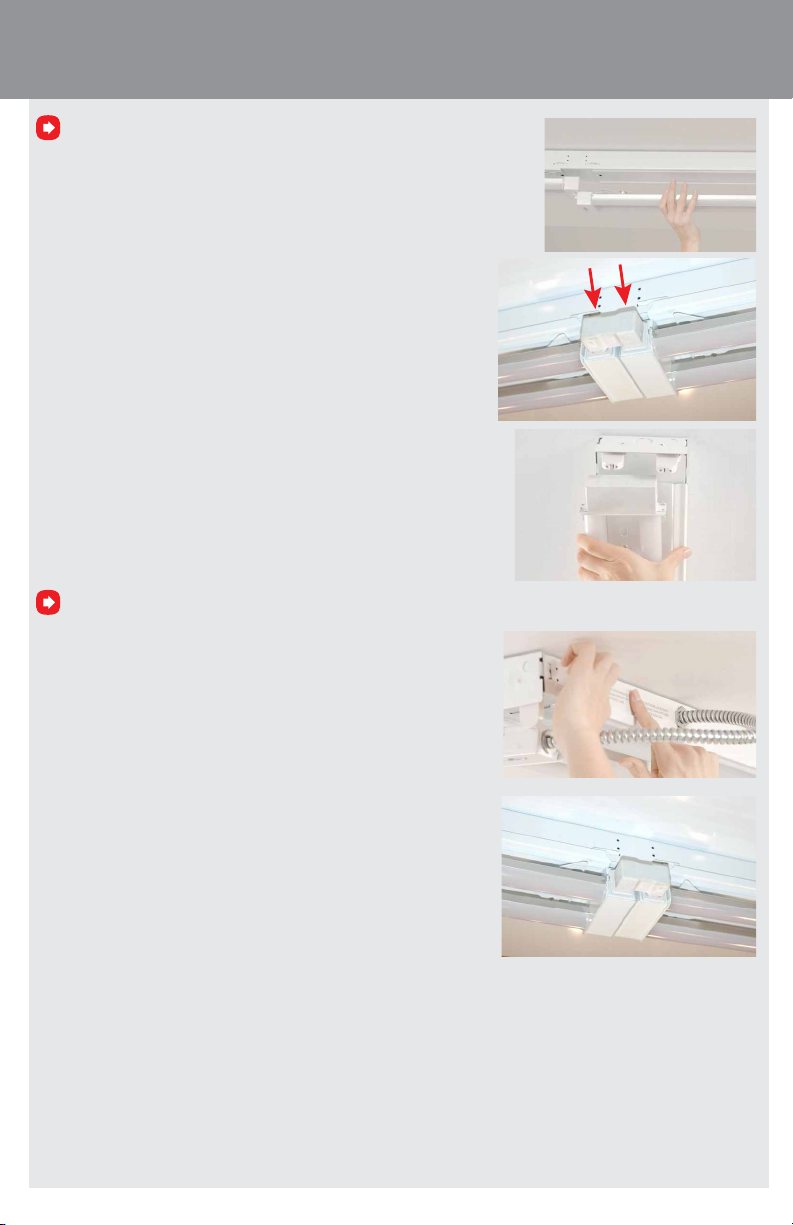
For 8’ install. Do not restore power until you complete steps 1a-1e below.
1a. Place and align the second 1’ x 4’ RetroFit with the C14 socket as close to
the rst Retrot as needed to allow use of RetroFit accessory connector.
1b. Place the dual connector (RFAC) into the sockets to connect both
the LED RetroFits together.
1c. Align the second xture and secure with 2 included self-tapping
screws
Any unused branch power circuits supplying interconnected retrot luminaires should be properly terminated.
1d. Apply both included labels to the xture.
1e. Restore the power and you’re done!
Our 1x4’s can be assembled into long chains o one power source depending on Retrot wattage. Connect
retrots when aligned together using the dual connector (RFAC).Connect retrots together when up to 8” apart
using 8in lamp to lamp extension cable (RFAC-8IN). Connect retrots together when 8”- 4’ apart using 4ft lamp
to lamp extension cable (RFAC-4FT). Cables shown on page 4.
Maximum number of units by Watts
16W = 36 Retrots
32W = 18 Retrots
45W = 12 Retrots
14
Page 15
Section 3
RF32UQT1XXC AND RF45UQT1XXC
TROFFER OR WRAP INSTALL
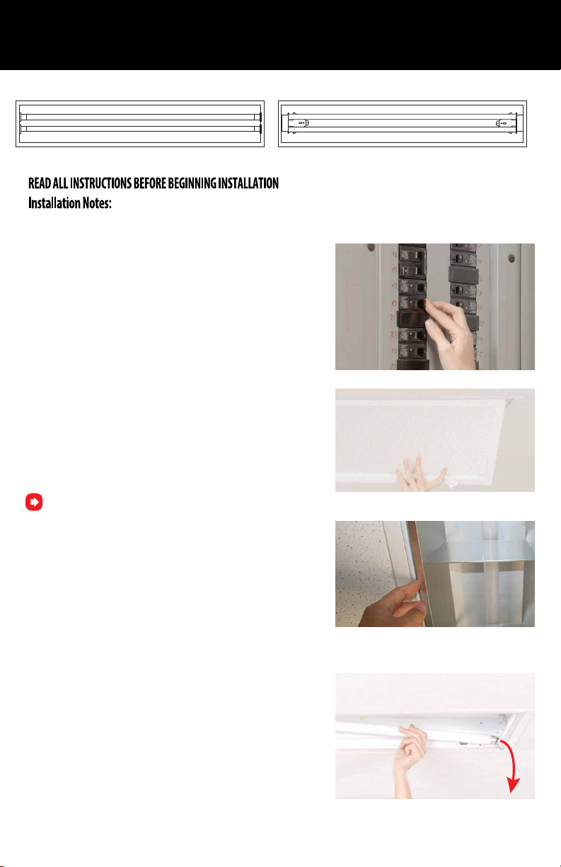
Before After
1x4 Troer Fixture with T8 Tubes 1x4 Troer Fixture with LED Retrot
1. Troer or wrap install requires the use of a junction box.
1. Turn o power to xture from circuit breaker.
2. Open and remove xture cover.
NOTE: RF45UQT1XXC is designed for retrotting a recessed
luminaire with an open lamp compartment and not for
retrotting a recessed luminaire with a diuser that fully
encloses the lamp compartment.
3. Remove uorescent tubes and ballast cover. Recycle tubes
according to EPA guidelines (EPA.Gov).
15
RF32UQT1XXC (closed xture)
RF45UQT1XXC (open xture)
Page 16
RF32UQT1XXC AND RF45UQT1XXC
TROFFER OR WRAP INSTALL
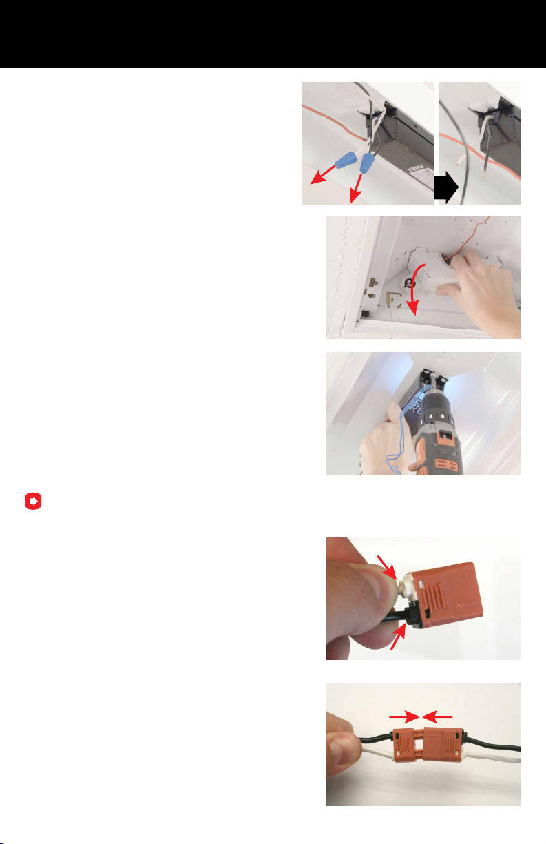
4. Disconnect ballast wires from the incoming
electrical line. (black and white wires)
5. Remove lamp holders and mounting bracket.
6. Unscrew and remove ballast from xture.
If you are installing LED retrot into a wrap xture, instead of removing the lamp holders, just cut the remaining
ballast wires as close to the lamp holders as possible.
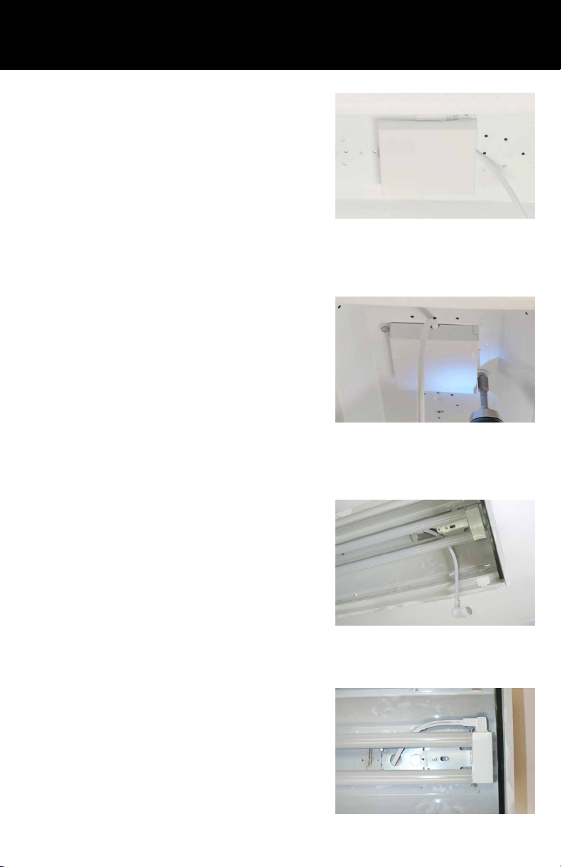
7. Push the incoming electrical wire leads into the back of the
included female disconnect. They will lock in place.
8. Connect the male disconnect to the female disconnect
attached to the included power cord.
16
Page 17
RF32UQT1XXC AND RF45UQT1XXC
TROFFER OR WRAP INSTALL
9. Fully cover the attached disconnect and incoming electrical
wires with provided magnetic junction box cover. Make sure the
power cord is aligned to allow connection to the LED RetroFit.
10. Secure junction box with 2 of the included self-tapping
screws.
11. Thread power cord between the two tubes of the LED
RetroFit. Ax the LED RetroFit to the xture using the rare earth
magnets. Slide the LED RetroFit to preferred alignment and
secure to the xture with 2 of the included self-tapping screws.
12. Plug power cord into Retrot power socket.
17
Page 18
RF32UQT1XXC AND RF45UQT1XXC
TROFFER OR WRAP INSTALL
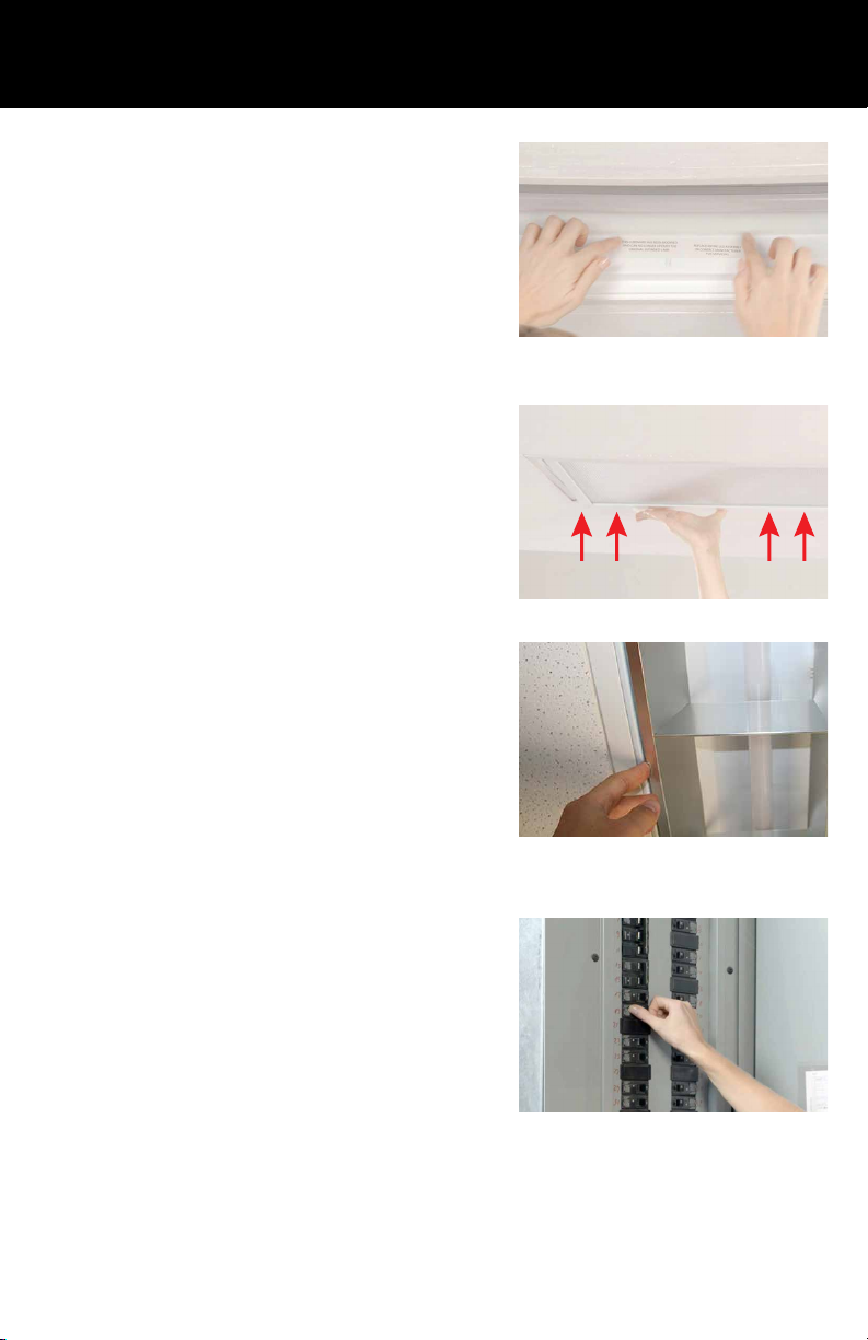
13. Apply both included labels to xture.
14. Replace the lens/xture cover.
RF32UQT1XXC (closed xture)
15. Restore the power and you’re done!
RF45UQT1XXC (open xture)
18
Page 19
Section 4
RF32UHT1XX, RF45UHT1XX, RF32UQT1XXC AND RF45UQT1XXC
STANDALONE USE
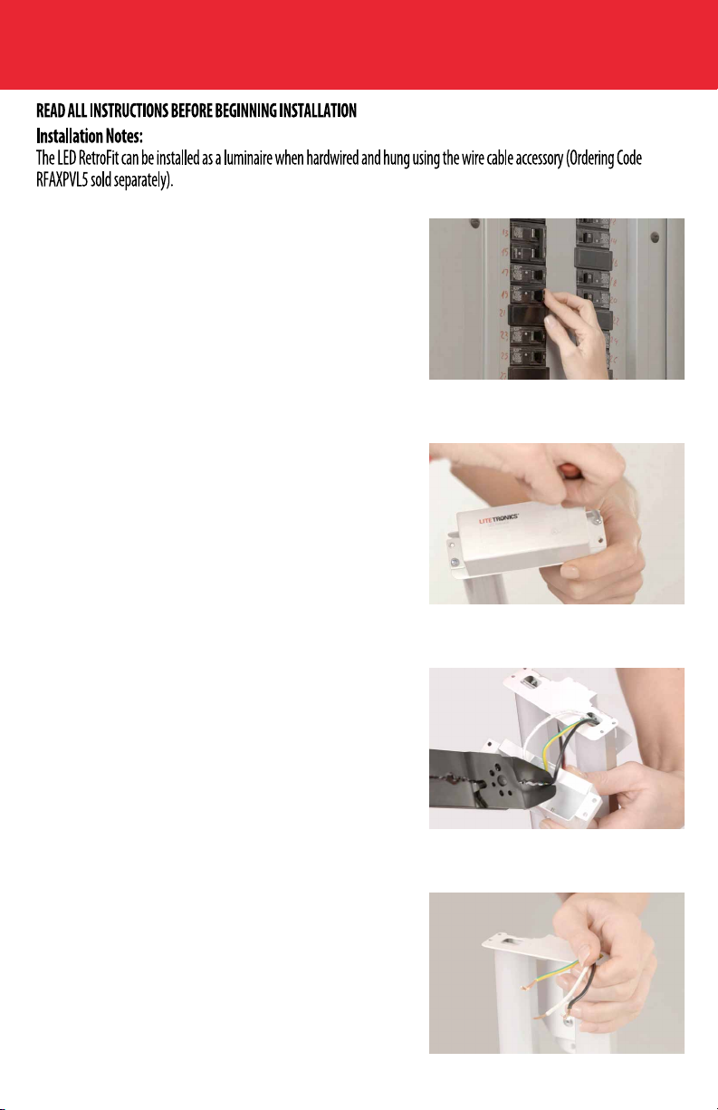
1. Turn o the power to the xture from the circuit breaker.
2. Open the end cover with Litetronics logo by removing both
screws of the LED RetroFit.
3. Cut the black, white and green/yellow wires close to the
power socket of the LED Retrot.
4. Strip the black, white and green/yellow wires to expose
about ¼” of wire.
19
Page 20
RF32UHT1XX, RF45UHT1XX, RF32UQT1XXC AND RF45UQT1XXC
STANDALONE USE
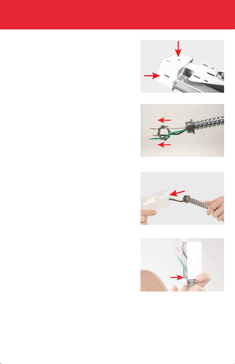
5. Remove the chosen knockout from end cover to make
hole to connect conduit.
6. Unscrew the conduit nut from the conduit.
7. Insert the three conduit wires (black, white & green) through
the hole in end cover.
8. Then place the conduit nut over the three conduit
wires inside end cover. After that, place conduit through
knockout hole and secure with conduit nut.
20
Page 21
RF32UHT1XX, RF45UHT1XX, RF32UQT1XXC AND RF45UQT1XXC
STANDALONE USE
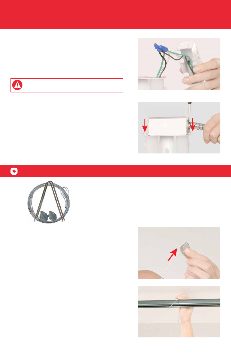
9. Connect conduit wires to the RetroFit with wire nuts. Connect
black to black, white to white and green to green/yellow.
CAUTION: To avoid risk of an electric shock, do not
connect wires from conduit directly to the socket.
10. Replace the end cover you removed earlier and secure it
with 2 screws.
Now, it is time to mechanically hang the light using the wire cable accessories.
Wire cable accessories
for stand alone installations
(RFAXPVL5)
11. Thread the non loop side of the cable into the cable lock,
and pull the cable through the lock.
12. Loop cable around ceiling or service attachment point and
pass tail end of cable through the other hole of the cable lock.
21
Page 22
RF32UHT1XX, RF45UHT1XX, RF32UQT1XXC AND RF45UQT1XXC
STANDALONE USE
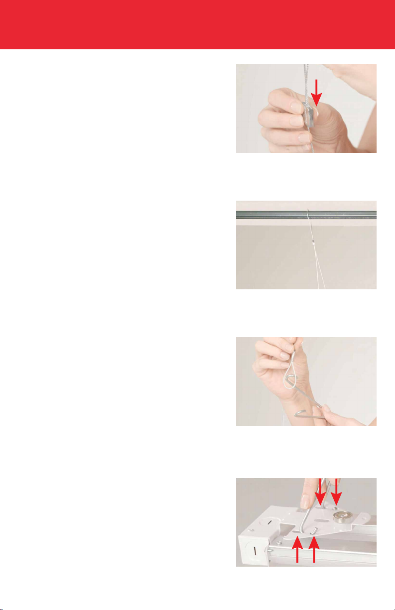
13. Pull the tail end of the cable through the cable lock so the
LED RetroFit hangs at desired height.
14. Repeat steps 12-14 with the second wire cable and lock.
15. Put both V hooks in the loops of the cables.
16. Locate the holes on the back of the mounting bracket of both
ends of the LED RetroFit.
22
Page 23
RF32UHT1XX, RF45UHT1XX, RF32UQT1XXC AND RF45UQT1XXC
STANDALONE USE
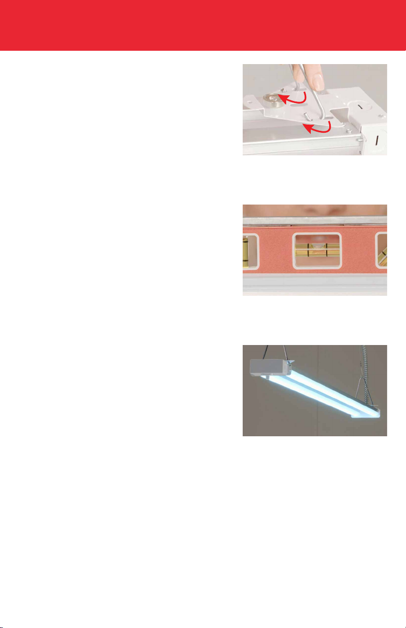
17. Insert both V hooks into the holes on the mounting bracket
(both sides of LED RetroFit).
18. Put a level on the LED Retrot for nal leveling, and adjust
the cable length to level the LED RetroFit.
19. Restore the power and you’re done! Enjoy your new energy
saving LED Light.
23
Page 24
RF32UHT1XX, RF45UHT1XX, RF32UQT1XXC AND RF45UQT1XXC
INTERCONNECTING STANDALONE USE
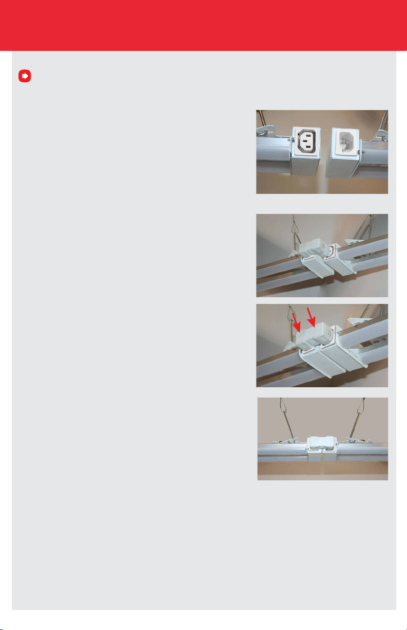
For interconnecting install. Do not restore power before you complete steps 1a-1c below.
1a. Place and align the second 1’ x 4’ LED RetroFit with the C14
socket as close to the rst LED Retrot as needed to allow use of
RetroFit accessory (RFAC, RFAC-8IN or RFAC-4FT) by repeating the
wire cable accessory steps 11-18 in this section.
1b. Place the Retrot accessory (RCAC, RFAC-8IN or RFAC-4FT)
to connect both the Retrot’s together.
1c. Restore the power and you’re done! Enjoy your new energy
saving LED RetroFit
Our 1x4’s can be assembled into long chains o one power source depending on Retrot wattage. Connect
retrots when aligned together using the dual connector (RFAC).Connect retrots together when up to 8” apart
using 8in lamp to lamp extension cable (RFAC-8IN). Connect retrots together when 8”- 4’ apart using 4ft lamp to
lamp extension cable (RFAC-4FT). Cables shown on page 4.
Maximum number of units by Watts
32W = 18 Retrots
45W = 12 Retrots
24
Page 25

252627
Page 26

Page 27

Page 28

Thank you for choosing
6969 W. 73rd Street
Bedford Park, IL 60638
WWW.LITETRONICS.COM
[email protected] or 1-800-860-3392
vol.5(3-29-17)
 Loading...