

Page 1
NON-SENSOR MODEL
LED PL High Bay
Installation Instructions
Ordering Code: HBC Series
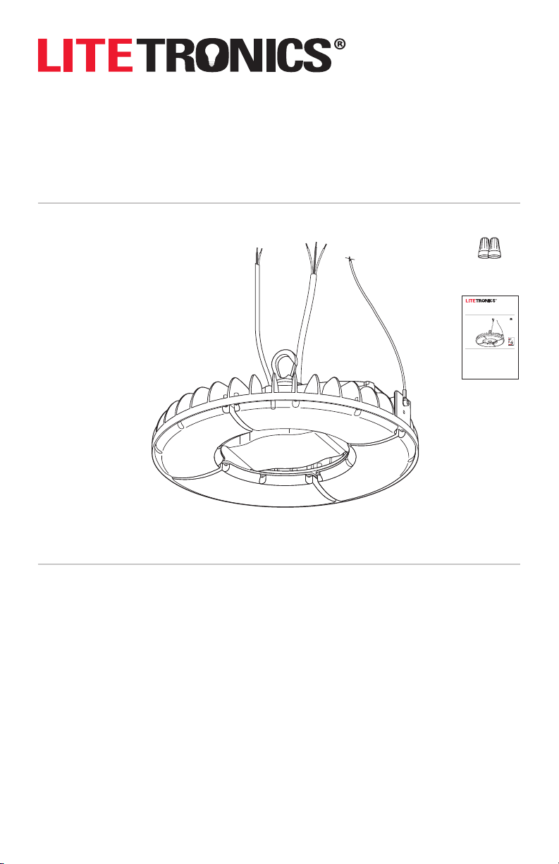
WHAT COMES IN THE BOX
(a) Built in 1’ 0-10V dimming wires (non-sensor model only)
(b) Snap hook
(c) Input wire (10’)
a
c
d
(d) Safety c able (5’) and bolt
(e) Two waterproof wire nuts (non-sensor model only)
(f) Installation instructions
TOOLS NEEDED
b
Wire Stripper
Wire Cutter
Non-sensor model
SAFETY INSTRUCTIONS AND WARNINGS
WHEN USING ELECTRICAL EQUIPMENT, BASIC SAFETY PRECAUTIONS SHOULD ALWAYS BE OBSERVED
READ AND FOLLOW ALL SAFETY INSTRUCTIONS.
• Consult a qualified electrician to ensure correct branch circuit conductor.
• Consulter un électricien qualifié pour vous assurer queles conducteurs de la dérivation sont adéquats.
• This product must be installed in accordance with the applicable installation code by a person familiar with the construction
and operation of the product and the hazards involved.
• Ce produit doit être installé selon le code d’installation pertinent, par une personne qui connaît bien le produit et son
fonctionnement ainsi que les risques inhérents.
• Installation should only be conducted by a qualified electrician in accordance with NEC and any relevant local building codes.
• Risk of fire or electric shock. High Bay installation requires knowledge of luminaires electrical systems. If not qualified, do not
attempt installation. Contact a qualified electrician.
• Be certain electrical power is OFF before and during installation and maintenance.
• High Bay must be connected to a wiring system with an equipment–grounding conductor.
• Make sure the supply voltage is the same as the rated High Bay voltage.
• To prevent wiring damage or abrasion, do not expose wiring to edges of sheet metal or sharp objects.
• No user serviceable parts inside of High Bay luminaires.
• Secure heat sink with safety cable.
e
(Non-sensor model only)
LED High Bay PL
Installation Instructions
Ordering Code: HBC Series
WHAT COMES IN THE BOX
(a) Built in 1’ 0-10V dimming wires (non-sensor model only)
(b) Snap hook
(c) Input wire (10’)
(d) Safety cable (15’)
(e) Two waterproof wire nuts (non-sensor model only)
(f) Installation instructions
TOOLS NEEDED
Wire Stripper
Wire Cutter
SAFETY INSTRUCTIONS AND WARNING S
WHEN USING ELECTRICAL EQUIPMENT, BASIC SAFETY PRECAUT IONS SHOULD ALWAYS BE
OBSERVED INCLUDING THE FOLLOWING:
READ AND FOLLOW ALL SAFETY INSTRUCTIONS.
• Consult a qua lified elec trician to ensure c orrect branc h circuit conduc tor.
• Consulter un électricien qualifié pour vous assurer queles conducteurs de la dérivation sont adéquats.
• This prod uct must be inst alled in accordan ce with the applic able installat ion code by a perso n familiar with th e constructio n
and operation of the product and the hazards involved.
• Ce produit d oit être install é selon le code d’ installation p ertinent, pa r une personne q ui connaît bien le p roduit et son
fonctionnement ainsi que les risques inhérents.
• Installa tion should onl y be conducted by a q ualified ele ctrician in acco rdance with NEC and a ny relevant loca l building codes .
• Risk of fi re or electric s hock. High Bay ins tallation req uires knowled ge of luminaires el ectrical sy stems. If not qua lified, do not
attempt installation. Contact a qualified electrician.
• Be certa in electrica l power is OFF befor e and during inst allation and maint enance.
• High Bay mus t be connected to a w iring system w ith an equipment– grounding cond uctor.
• Make sure the s upply voltage is t he same as the rate d High Bay voltage .
• To prevent wirin g damage or abrasi on, do not expos e wiring to edges of s heet metal or sh arp objects .
f
• No user ser viceable par ts inside of Hig h Bay Lumiaire.
• Secure he at sink with safet y cable.
(Non-sensor model only)
Page 2
INSTALLATION PROCEDURE INSTALLATION PROCEDURE
READ ALL INSTRUCTION BEFORE BEGINNING INSTALLATION
1. Turn off power at the circuit breaker.
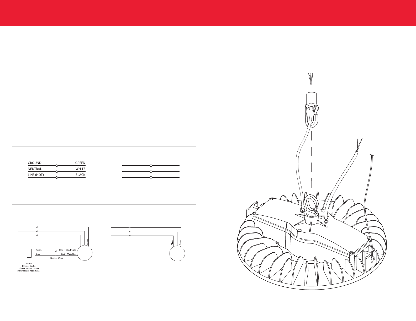
2. High Bay Luminaire should be mechanically supported to hook, chain or cable (not included) by securing to snap hook
(included) on top of fixture.
3. Once luminaire is supported, attach the included safety cable to a beam or permanent structural support.
4. Make wiring connections
• For non-sensor model, make connections between dimming wires (purple (+) and gray (-)) and dimmer with the
included waterproof wire nuts. Then connect input wire to AC branch circuits as noted in figure 1. This should be in
accordance with national and local codes. Reference wiring diagram below (figure 3)
• For sensor model, connect input wire to AC branch circuits as noted in figure 1. This should be in accordance with
national and local codes. Reference wiring diagram below (figure 4). The sensor must be set using a remote control,
part # SCR053 (sold separately). Instructions for sensor settings are included with each remote control.
5. Restore power at circuit breaker and subsequently switch on dimmer (if applicable).
Line/neutral/ground
0-10V dimming
120V & 277 V
480V
GROUND
LINE 1 (HOT)
LINE 2 (HOT)
figure 1 figure 2
*For 347V, follow 120-277V wiring instructions*For 240V, follow 480V wiring instructions
Non-sensor model Sensor model
White/Blue
Black/Brown
LED Round High Bay PL
figure 3 figure 4
GREEN
WHITE
BLACK
White/Blue
LED Round High Bay PL
Safety cable
2
3
Page 3

Thank you for choosing
6969 W. 73rd Street
Bedford Park, IL 60638
WWW.LITETRONICS.COM
[email protected] or 1-800-860-3392
The information and product specifications contained in these
instructions are based upon data believed to be accurate at the time
of printing. This information is subject to change without notice and
without incurring liability. If you have questions regarding specific
product details, please contact us at 800-860-3392 or via email at
[email protected].
To check for an updated version of these instructions,
please visit www.litetronics.com.
v3 (12/27/18)
 Loading...