

Page 1
Users Manual
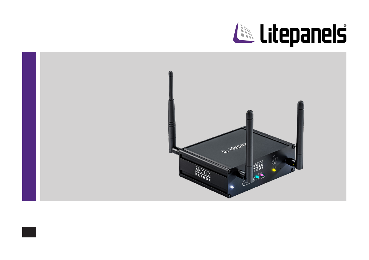
Apollo Wireless DMX Bridge
Powered By Lighticians
Apollo Wireless DMX Bridge
EN
Part No. 900-4014
www.litepanels.com
Page 2

Copyright © 2020
All rights reserved.
Original Instructions: English
All rights reserved throughout the world. No part of this publication may be stored in a retrieval system, transmitted, copied or reproduced in any
way, including, but not limited to, photocopy, photograph, magnetic or other record without the prior agreement and permission in writing of the Vitec
Group Plc.
Disclaimer
The information contained in this publication is believed to be correct at the time of printing. Vitec Production Solutions Ltd reserves the right to
make changes to the information or specications without obligation to notify any person of such revision or changes. Changes will be incorporated
in new versions of the publication.
We are making every eort to ensure that our publications are updated on a regular basis to reect changes to product specications and features.
Should this publication not contain information on the core functionality of your product, please let us know. You may be able to access the latest
revision of this publication from our website.
Vitec Production Solutions Ltd reserves the right to make changes to product design and functionality without notication.
Trademarks
All product trademarks and registered trademarks are the property of The Vitec Group Plc.
All other trademarks and registered trademarks are the property of their respective companies.
Published by:
Vitec Production Solutions Ltd
Email: [email protected]
Page 3

Contents
Safety..................................... 2
Intended Use .......................... 2
Health and Safety....................... 2
Features...................................4
Introduction............................4
Elements . . . . . . . . . . . . . . . . . . . . . . . . . . . . . . . . . . 5
Operating Elements . . . . . . . . . . . . . . . . . . . . . . . . . 6
LED Indicators ............................. 7
Operation..................................8
Initial Setup and Connections.............. 8
Unlinking..............................8
Device Conguration ................... 10
Updating Firmware..................... 11
Radio Frequency, Interference Management . 12
Selecting a WiFi Channel................13
Dense WiFi Environments ............... 13
Specications .............................16
General Notices ........................... 17
High Gain and Other 3rd Party Antennae....13
Troubleshooting ...........................14
Kits / Spare Parts .......................... 15
Page 4
Safety
!
!
!
!
!
Intended Use
This product is intended to transmit and receive lighting control data
in a dry environment. Always follow the safety guidelines.
Not for use as a router or access point for life saving applications or
for medical equipment
Health and Safety
WARNING! Risk of personal injury or injury to others. All
personnel must be fully trained and adhere to correct manual
handling techniques and Health and Safety regulations. It is
the responsibility of the local organisation to enforce safe working
practices at all times.
Humidity and Condensation! Risk of electric shock
and re.
CAUTION! Never expose the product to rain or moisture as
condensed moisture may damage the product electrically
when switched on
CAUTION! Never cover the Apollo Wireless DMX Bridge
during operation. Keep a minimum clearance of 4 inches
around the housing for ventilation and air circulation
CAUTION! Avoid direct illumination by other luminaries or
other heat sources. Check the mains cable and connector
cable prior to every operation for damage.
Maintenance
WARNING! The tting of non-approved parts and or
accessories or servicing by non-approved personnel could
eect the safety of the product. It may also invalidate the
terms and conditions of the product warranty.
There are no user serviceable parts inside the enclosure. Only a
Litepanels qualied service center may open the Apollo Bridge.
The Apollo system is intended for professional use and may only be
operated by qualied persons.
Please read these instructions carefully before using the product for
the rst time. The following text contains important information for
safe handling.
NOTE! To check for updates to the Operators Manual,
visit:
www.litepanels.com
WARNING! In case of visible damage to the mains cable or
!
the housing, the device must not be operated any longer.
Damaged components must be replaced by a Litepanels
service center.
2
Page 5
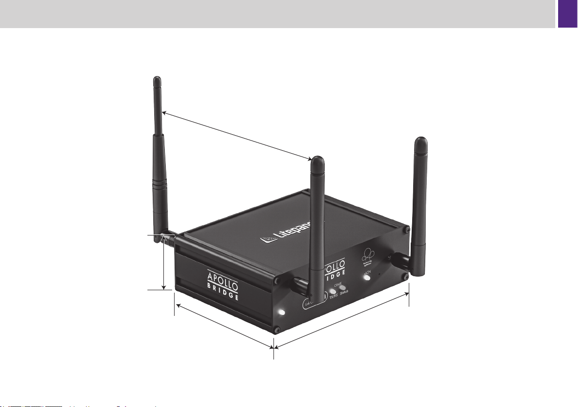
42mm
1.7”
Maximum spread:
190mm
7.5”
Dimensions
104mm
5.7”
144mm
5.7”
3
Page 6

Features
• Modern Quad Core ARM CPU and custom Router SoC with
Enterprise Grade WiFi and Ethernet to support low latency high
performance networking.
• WiFi 5 (802.11ac Wave2 with MIMO) with full support for all
related security and encryption standards.
• Simultaneous Dual Band 2.4/5 GHz WiFi.
• Dual 1Gbps Ethernet Ports supporting two separate networks,
WAN/LAN routing functionality, or bridged as a switch.
• LumenRadio TimoTwo CRMX transceiver.
• Web based conguration and advanced provisioning features.
• Multiple physical and virtual ports for DMX distribution:
• E1.11 DMX on 5-Pin XLR.
• LumenRadio CRMX.
• E1.31 sACN over Ethernet and WiFi.
• USB 3.0 on USB-A connector for external expansion.
• Firmware updates over Ethernet and WiFi using the Web GUI.
• USB-C Power Input.
• Rugged design.
• 1/4”-20 threaded mount for rigging hardware.
• Highly visible indicator LEDs for power, mode, LumenRadio, and
device status.
• Compatible with any E1.31 sACN control application or lighting
console.
• Compatible with any LumenRadio CRMX wireless receiver.
Introduction
Thank you for choosing the Apollo Wireless Lighting ecosystem from
Litepanels: Powered by Lighticians. The Apollo Wireless Lighting
Bridge is the ultimate “Swiss Army Knife” of wireless lighting control.
This universally compatible bridge connects to any DMX xture
via wireless DMX, Ethernet, 5-pin XLR, or WiFi. It connects to any
LumenRadio CRMX receiver and integrates the state-of-the-art
TimoTwo module for robust wireless DMX transmission even in the
most crowded radio frequency environments.
The Apollo Bridge also is an enterprise grade network router that can
be congured for sophisticated data networking. Conguration and
provisioning is performed using an intuitive web based interface from
any web browser including on mobile devices and tablets. WiFi is
supported simultaneously on both 2.4 GHz and 5 GHz bands, giving
the user enhanced and automatic interference avoidance with other
on-set wireless equipment.
Apollo is a two-part system that enables wireless DMX
communication to Litepanels xtures, such as the Astra and Gemini,
along with most other DMX controllable lighting devices. The Apollo
Bridge uses LumenRadio CRMX for wireless DMX communication to
xtures and E1.31 sACN over WiFi or Ethernet for direct control from
a mobile device, computer or lighting console.
Operators nally have a device that can be trusted on any location
and implemented into existing data workows, regardless of what
equipment or protocols are being used. Meanwhile, rst time wireless
customers have an intuitive and reliable solution that enables more
powerful control without needing to be a DMX or networking expert.
When used in concert, along with Litepanels xtures, these two
products complete a lighting ecosystem that seamlessly and without
interruption empowers lighting creatives with fast uid control that
maximizes their craft.
4
Page 7
Elements
Antennae
The Apollo Wireless DMX Bridge includes 2× RP-SMA antennae for
dual band WiFi, and 1× RP-TNC antenna for CRMX transmission.
Power Supply
The Apollo Wireless DMX Bridge uses the included 9V/2A USB-C
universal power supply. 5V USB power is insucient for this device.
Only USB Type-C PD compliant power supplies will boot the device.
Insucient power will be indicated by a rapidly ashing red power
LED.
Control
The Apollo can receive and route sACN from any mobile device,
tablet, computer or console with that supports the E1.31 sACN
standard. Control signals can be mapped to any or all available
outputs including physical XLR and LumenRadio ports.
Conguration Options
The Apollo Wireless DMX Bridge can be congured using an intuitive
web GUI by entering the device’s IP address into a web browser
while connected to the Apollo network. The default IP address is
10.1.0.1. CRMX Link/Unlink actions can be done both remotely in the
LumenRadio CRMX Toolbox App or locally using the physical Link
button.
Printed Label (Bottom of the Device)
The printed label on the bottom of the device contains all of the
information pertaining to initial access including the default password.
Please take a photo, record, and safely preserve this information.
When at some future time you reset the device to factory defaults (for
example after wrapping a show or upon checking out a new location
rigging package) you will need this information to re-provision your
Apollo Bridge.
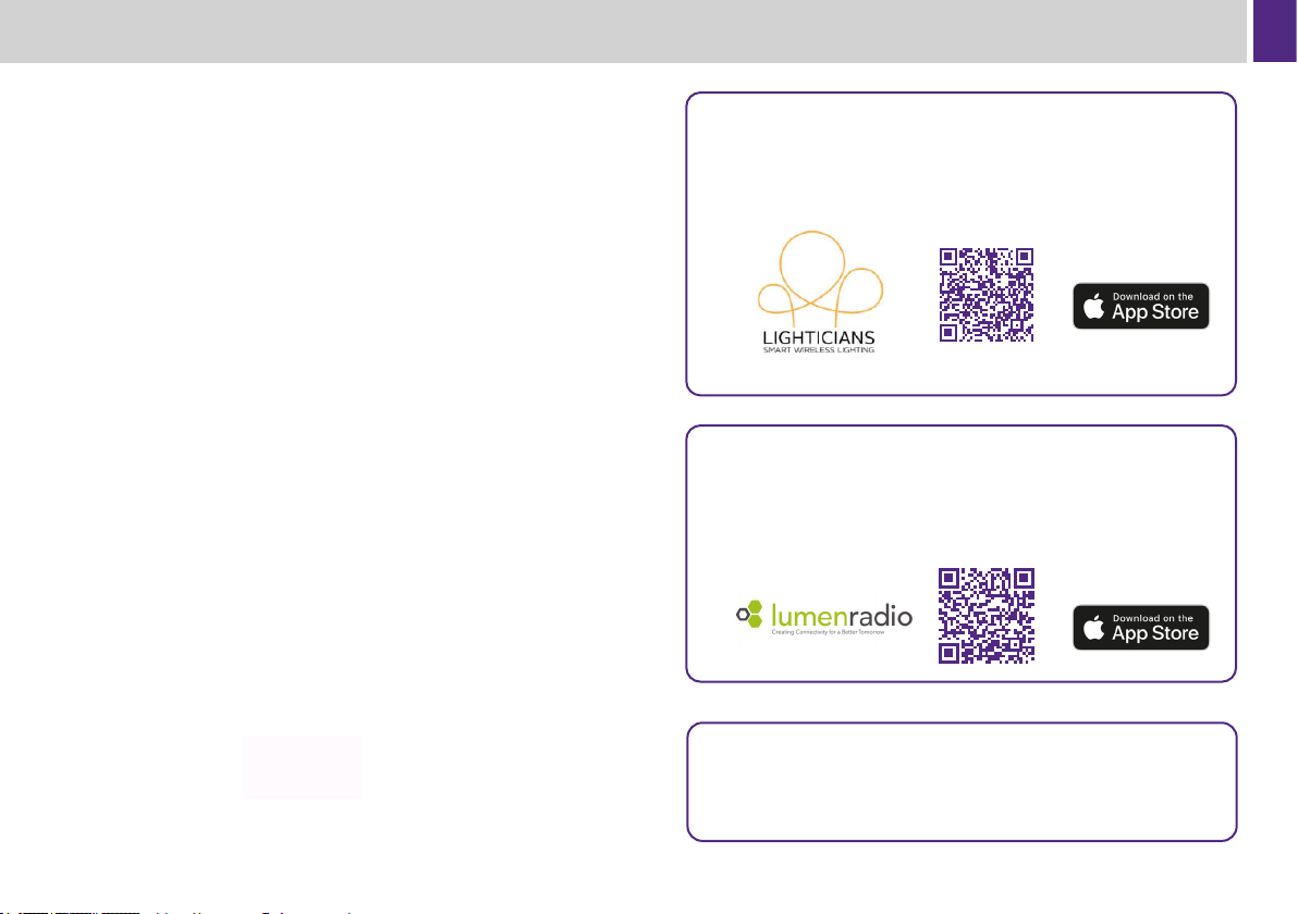
Download the “free Lighticians Apollo Control App”
To control all of your Litepanels lights and other lighting xtures in
your kit, scan the QR code with your iPhone or iPad to install the app.
Download the free CRMX Toolbox app
For additional CRMX transmitter settings, download the free CRMX
Toolbox app from the app store, scan the QR code with your iPhone
or iPad to install the app.
Note! This product contains software licensed under various
free software licenses, please refer to the “License Notices”
section in Apollo’s integrated web based control portal for
more information.”
5
Page 8
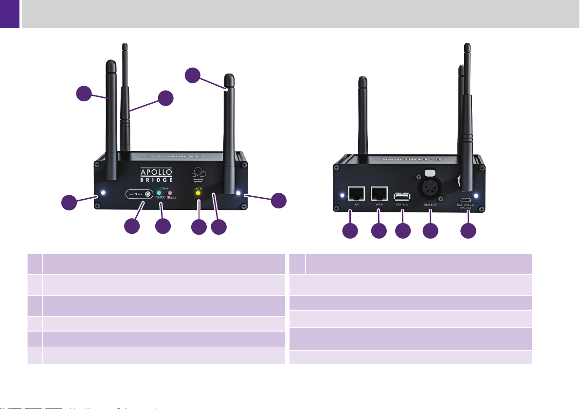
Operating Elements
1
1
2
Front View
6
3
Dual-band 2.4GHz and 5GHz Antennas sends and receives sACN Wi-Fi
1
transmission
Long LumenRadio CRMX Antenna transmits wireless DMX to CRMX
2
receivers
Link/Unlink CRMX press to link CRMX to receivers. Hold 3+ secs to unlink
3
all receivers
CRMX Indicator LEDs display CRMX mode, status and data
4
sACN Indicator LED displays status of sACN network and network ports
5
Corner System Indicator LEDs displays device system status
6
4
5
7
Rear View
6
10
9
8
Reset Pinhole Button press to reboot or hold for 3 seconds to reset to
7
factory default settings
LAN RJ45 Port connect to sACN Local Area Network devices such as
8
a lighting console
9
WAN RJ45 Port connect to Wide Area Networks, such as the internet
10
USB 3 Port for use with future features and accessories
5-Pin DMX In/Out connect to hard-wired DMX controlled xtures or to a
11
DMX lighting board. Defaults to output
12
USB-C Power Port connect from 9V+ USB-C power supply or battery
11
12
6
Page 9
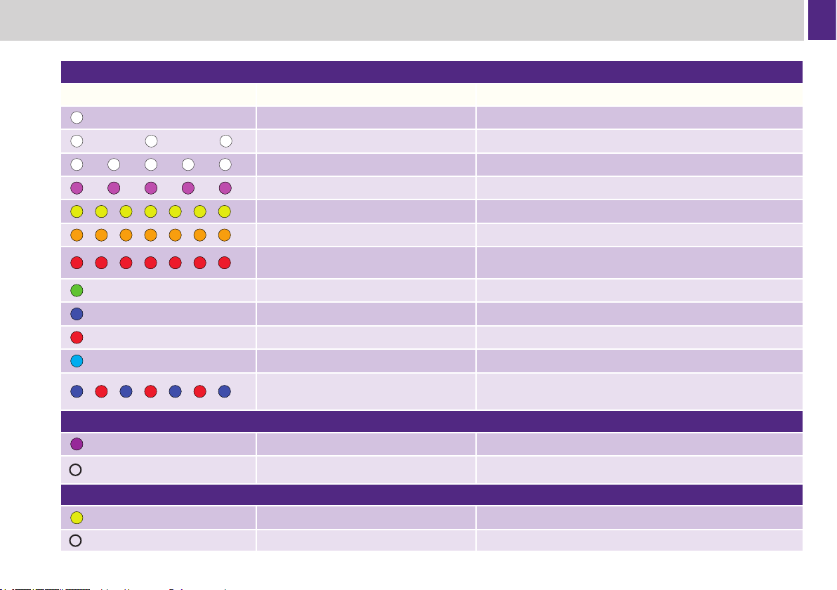
LED Indicators
Four corner “Status LED”
LED Behaviour LED Meaning
White constant on System nished booting, no error
White slow ashing System booting
White fast ashing Press “RESET” button to enter failsafe
Pink fast ashing Contact Litepanels Support
Yellow very fast ashing System is in failsafe mode
Orange very fast ashing Contact Litepanels Support
Red very fast ashing
Green constant on Contact Litepanels Support
Blue constant on Contact Litepanels Support
Red constant on Contact Litepanels Support
Cyan constant on Contact Litepanels Support
Extremely fast ashing, alternating blue
and red
LumenRadio Timo LED
Purple, constant on Port is in TX mode
USB-C supply has insucient power, try switching to a dierent
known to be reliable power source or switch power cables
Contact Litepanels Support
O Port is disabled
sACN LED
Yellow, constant on: Port is in RX mode
O Port is disabled
7
Page 10

Operation
Initial Setup and Connections
Plug in the Apollo Bridge
Attach the appropriate AC power connector to the included 9V USB-C
power supply and then plug the USB-C connector into the female
input on the rear of the Apollo Bridge. Then connect to an AC power
receptacle. The unit will power on and be ready within 90 seconds.
Simply plug any LumenRadio CRMX Receiver into the DMX IN port
on a DMX capable xture.
You can now connect to the Apollo network via WiFi or Ethernet
(using the LAN port).
General Operation
Operating Range
The Apollo Bridge has a range of up to 300m via CRMX transmission
and up to 100m via WiFi. External factors, such as other radio
interference and walls, vegetation, or even people between the
Bridge and Receivers can impact the range. Best practice is to have
an uninterrupted line-of-sight (LOS) between the Apollo Bridge, the
receivers as well was the control device.
Connecting to the Apollo WiFi Network
To log in to the Apollo Wireless DMX Bridge, rst connect to the Apollo
network on your mobile device or computer by nding the “Apollo
Bridge” network in your list of WiFi networks and then joining it as you
would your home router or oce access point. Enter the password
when requested.
Note! The Apollo Wireless DMX Bridge default password is found on
the label on the bottom of the bridge’s enclosure. The default Network
SSID is “Apollo Bridge”.
Please note that all passwords are case sensitive.
8
Linking CRMX Receivers
After ensuring your wireless DMX Receivers are powered and unlinked,
briey press the CRMX Link Button on the front of your Apollo Wireless
Bridge. The Status Light on your Apollo Bridge will blink for several
seconds in unison with the CRMX Status Light on linking CRMX
receivers. Linking is complete when ashing stops.
Receivers will stay linked to their transmitter indenitely until unlinked
and/or linked to another transmitter.
Unlinking
Unlink One Receiver
On a third party CRMX Receiver, press and hold its Unlink button for
more than 3 seconds to unlink it from a transmitter. The CRMX indicator
will extinguish.
To unlink the CRMX receiver in a Litepanels Gemini or Astra in the menu
select:
SETTINGS > DMX SETTINGS > WIRELESS DMX > UNLINK
Unlink All Receivers
On the Apollo Bridge, press and hold the Link button for more than 3
seconds to unlink all receivers currently paired with the Apollo Wireless
DMX Bridge.
Think carefully before taking this action as there is no “undo” in this case.
Unlinking all connected receivers will require you to relink each one to
regain control.
Download the Apollo Control App
Optionally, if you do not have a suitable sACN lighting controller,
download the free Lighticians’ Apollo Control app rst before moving
forward.
Scan the QR code with your iPhone
or iPad to install the app
Page 11

Operation
Controlling Your Lights
Now that your tablet or device is connected and your receivers are
linked, open the Lighticians’ Apollo Control app or another sACN
compatible lighting control application of your choice. The Apollo
Lighting Control App supports E1.31 sACN as a default. Some other
apps, software, or consoles (especially from ETC) require sACN to be
enabled. In those cases, the following settings are recommended:
IP Address: .. .... .. .... .. .DHCP/Auto
Protocol: ... .. .... .. .... .. .E1.31/sACN
sACN Universe: .. .... .. .1
The Apollo Wireless Lighting Bridge is capable of outputting a
single universe of 512 DMX addresses mapped to any number of its
interfaces.
Conguring The Gemini For Apollo App Control When
Using Litepanels CRMX Dongle.
1. Power on Gemini and insert in designated slot on top of the
xture. Green light on dongle will turn on when inserted correctly.
2. On your Gemini select SETTINGS > IN/OUT SELECT >
WIRELESS DMX IN.
3. On your Gemini Select DMX VERSION > DMX SETTINGS >
DMX VERSION > VER 1 (ORIGINAL).
4. On your Gemini Select DMX RESOLUTION > 8 BIT (If you want
smoother dimming select 16 BIT but make sure you patch a 16
BIT prole when setting the light up in your control app or on
your console).
5. On your Gemini Select DMX ADDRESS > select the starting
DMX address that will correspond with starting DMX you use
when patching the light in the app.
6. On your Gemini Select DMX MODE CONTROL > ENABLE
7. On your Gemini Select WIRELESS DMX > UNLINK (this
resets the dongle and unlinks from any transmitter it may have
previously connected to).
8. On your Gemini Select WIRELESS DMX > LINK. Immediately
press the CRMX link button on your APOLLO BRIDGE.
9. If the link is successful the 5 wireless bars at the top of the
Gemini menu will turn green.
Note! If using a Gemini 1×1 or a Gemini 2×1 with older software
these two additional steps are required when setting up the xture.
8.Select DMX VERSION > DMX SETTINGS > DMX VERSION > VER
1 (ORIGINAL).
9.Select DMX MODE CONTROL > ENABLE.
Conguring The Astra When Using Litepanels CRMX Dongle.
1. Insert the Wireless DMX module into your Astra and power on.
2. On your Astra select SETTINGS > DMX SETTINGS > DMX
ADDRESS > select the starting DMX address that will correspond
with starting DMX you use when patching the light in the app.
3. On your Astra select SETTINGS > DMX SETTINGS >
WIRELESS DMX > SET RADIO ON.
4. On your Astra select WIRELESS DMX > UNLINK RADIO (this
resets the dongle and unlinks from any transmitter it may have
previously connected to).
5. On your Astra select WIRELESS DMX > LINK RADIO
6. Immediately press the CRMX link button on your APOLLO
BRIDGE.
7. If the link is successful the 5 wireless bars at the top of the
Gemini menu will turn green.
9
Page 12
Operation
Hardware Reboot
It is sometimes necessary to reboot the bridge using the external
button. To reboot the Apollo Wireless Bridge, briey press the
recessed button inside the small pinhole labelled “RESET” on the
front of the bridge. Do not hold the reset button for longer than a few
moments or a factory default reset will initiate.
The device status LEDs will blink in white indicating that it is
rebooting.
Upon completion of the reboot the device will return to normal
operation without any further user intervention.
Factory Reset
When performing a factory reset the bridge will erase all customized
settings including any settings adjusted on the advanced control
pages back to the original state of device as delivered from the
factory. It will be necessary to recongure your Apollo Wireless Bridge
as if it were new. Please carefully consider this prior to initiating this
procedure as there is no undo once it begins.
To restore the Apollo Wireless DMX Bridge to factory default settings:
1. Connect power to the Apollo Wireless DMX Bridge.
2. Press and hold the recessed reset button inside the small
pinhole labelled “RESET” on the front of the bridge with a pen,
paperclip or other object for at least 5 seconds.
The device status LEDs will blink in yellow indicating that it is
restoring to factory defaults.
Upon successfully resetting the device status LEDs will return to solid
white. At this time you can connect to the device’s web GUI and follow
the initial conguration steps.
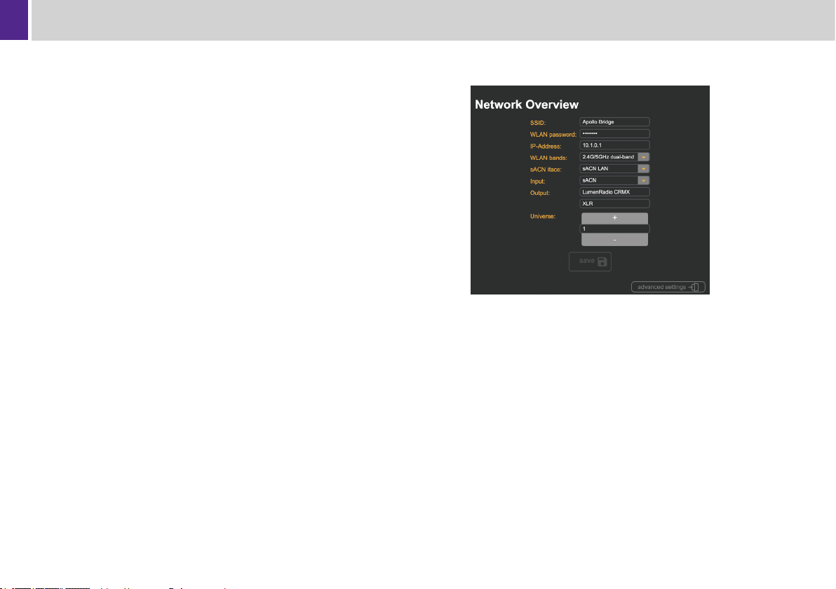
Device Conguration
All conguration of the Apollo Wireless DMX Bridge can be performed
using its integrated web based control panel. To access this:
1. Connect your iPhone, iPad, Mac or PC to the Apollo Wireless
DMX Bridge WiFi using the SSID and password displayed on
the bottom of the Apollo Bridge; or connect your PC to the LAN
Ethernet port.
2. Open a web browser on the connected computer or mobile
device.
3. Enter the IP address of the Apollo Wireless Bridge into the URL
box of the web browser. The default IP address is 10.1.0.1.
4. When prompted enter in the same network password as printed
on the bottom of the Apollo Bridge.
10
Page 13
Operation
Updating Firmware
Before proceeding with a rmware update insure that the Apollo is
powered by a reliable source and all physical connectors are rmly
attached. Performing a rmware update with the device powered by a
battery source is not recommended.
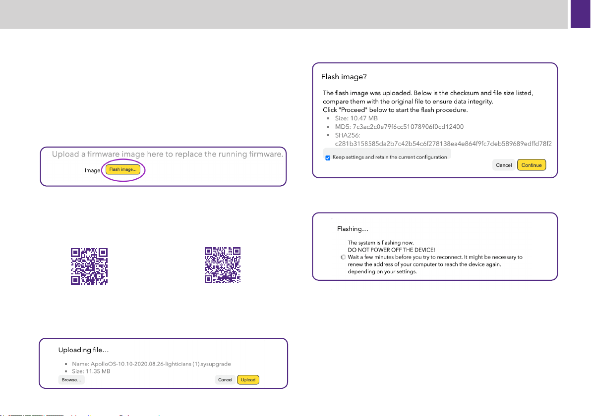
1. Select advanced settings at the bottom of the Web Portal.
2. Select System on the left side menu.
3. Select Backup/Flash Firmware.
4. Select Flash Image.
5. Choose Browse.
6. Select the latest rmware zip les downloaded from:
or
www.lighticians.com/rmware
7. Select Upload.
www.litepanels.com/support/
apollo/rmware
8. Once the upload is complete you will be asked if you would like to
Flash Image? Select Continue to proceed.
9. While updating the below prompt will appear. You will be
disconnected from the network while the Apollo Bridge
automatically performs a normal reboot.
10. Once the LED indicators nish breathing and become solid,
you will be able to reconnect to the Apollo wireless network and
operate the device.
11. Settings are preserved through rmware updates so it is likely
that your WiFi connected devices will automatically reconnect.
Occasionally mobile devices will switch to a dierent WiFi network.
Check your device/computer WiFi settings to conrm that you
again are connected to your Apollo Bridge before proceeding with
normal operation or making additional conguration adjustments.
11
Page 14

Operation
Advanced Capabilities
In addition to acting as a self contained WiFi network, the Apollo
Wireless Bridge has several other ways of controlling and connecting
lighting devices.
Ethernet
The Ethernet port on the Base Station provides another connection
option. Other devices can connect to the sACN LAN and the use of
downstream bridges is completely supported. Using a large Ethernet
bridge, it is possible to connect many devices. The integrated WiFi
access point can be used in conjunction with wired Ethernet for multinode systems. As a default, the LAN network will always route to/from
all WiFi connected devices and share the same IP address pool and
subnet.
5-Pin XLR Input
Apollo can optionally receive and route DMX through the 5-pin XLR
DMX port. An XLR 5 pin Male-Male adaptor (not included) will be
required for this in addition to adjustments with the web GUI.
5-Pin XLR Out
The 5-pin XLR port will transmit the same active DMX universe as the
LumenRadio CRMX signal. This enables a wired network of xtures
using standard 5-pin DMX cables to be used simultaneously with a
LumenRadio CRMX network.
Multi-Universe Networks
If more than one universe is required, several Apollo Wireless DMX
Bridges can be set to dierent universe numbers and connected
together using an Ethernet switch. Each Apollo Wireless Bridge can
control its own set of paired LumenRadio CRMX Receivers and/or
XLR connected chains of DMX devices.
Apollo Receivers will need to be Linked to the individual Apollo
Wireless Bridges at dierent times. To Link the rst DMX Universe,
power on only the Apollo Receivers you wish to be associated with
that Universe. Then press the Link button on the back of the rst
DMX Universe Base Station. Repeat this process for the other DMX
Universes.
The DMX universe can be congured using the Apollo Wireless
Bridge web controls.
Advanced Routing and Networking
In addition to the lighting control features, many more advanced
routing and access point congurations are possible using the
“Advanced Settings” section of the web control panel. While
Litepanels cannot oer specic support for those installations
advanced users working with IT Departments or who have knowledge
of TCP/IP networking themselves will nd many more options
available by looking through the advanced pages.
Radio Frequency and Interference Management
Antennae Placement
For the best performance, the WiFi and CRMX antennae should be
articulated on dierent planes at 90° angles perpendicular to each
other.
For maximum range, the Apollo Wireless DMX Bridge CRMX Antenna
and CRMX Receiver antennae should be oriented in the same
direction, and all devices should have an uninterrupted line-of-sight
between them.
12
Page 15

Operation
If WiFi signal or latency problems such as lag or choppy DMX
performance persist, it may be necessary to adjust the position of
the two antennae on the Apollo Wireless Bridge. Tilting the antennae
perpendicular to each other can enhance the distance of the WiFi
signal.
If using other wireless transmission devices, such as other wireless
DMX devices or WiFi routers, it is suggested to maintain a minimum
of 15 feet between devices for optimum performance of both systems.
Selecting a WiFi Channel
The 2.4 GHz WiFi band is divided into 11 channels. Because WiFi
channels overlap, the number of WiFi channels allocated by default
on the Apollo Bridge is restricted to minimize interference from
surrounding WiFi networks. Using channels 1, 6 or 11 whenever
possible will help provide the most reliable WiFi signal strength while
minimizing interference.
This can be congured within the Advanced Settings pages within the
web controls.
Dense WiFi Environments
5GHz WiFi is built into the Apollo Bridge and enabled by default. Any
device supporting 5GHz WiFi will automatically connect using those
frequencies instead of the typically more crowded 2.4GHz band. In
environments with extremely high device counts or with numerous
other 2.4GHz/5GHz networks — be they WiFi or other networks on
the same bands; a Spectrum Analyzer can be used to determine the
least used frequency ranges making channel selection much more
accurate.
Typical use cases that may require a Spectral Analysis as part of
a site survey would include stadiums, arenas, houses of worship,
facilities within or adjacent to emergency services, university and
other scientic research facilities, etc.
High Gain and Other 3rd Party Antennae
Higher gain antennae increase range only in low noise environments
with clear line-of-sight. This always will increase noise along with the
desired signal as they are not a lter. Careful network planning and
layouts are stronger solutions than high gain antennae.
Additionally always obey all local laws and regulations pertaining to
radio use.
13
Page 16

Troubleshooting
Troubleshooting
Check that the Apollo Bridge is receiving reliable power and that
all physical connections are rmly seated. When troubleshooting
“mysterious” failures, reduced range, or sudden signal issues the
solution often can be switching the power source.
If the network does not appear on your device then reset the Bridge
by power cycling it. Note the bridge takes approximately 90 seconds
to fully boot.
Conrm CRMX receivers are linked to the Base Station and not
another transmitter. Also conrm that the receivers are properly
connected to the lighting xture
Conrm that only the lights selected are the ones you want to control
before entering the Color Wheel screen in the App.
Conrm the lighting xture is set to the correct DMX address, correct
mode and bitrate for the patched prole.
Conrm hardwired lighting xtures are connected to receivers or DMX
cables via the DMX IN connector on the on the light.
Conrm your control software is set to transmit E1.31 sACN.
Conrm that the control device or console is connected to Apollo
Bridge WiFi network or LAN Ethernet port.
If the CRMX receiver shows a strong connection but the xture is not
responding to commands, cycle the power on the xture.
If none of these x the problem, insert a pin into the hole ‘Reset’
and hold for 10 seconds to factory reset the bridge. You will have to
re-provision the bridge as a new device after it reboots.
Tips
When Connecting with an iOS/iPadOS Device
• Turn o auto join for any networks this device has connected to
by going to SETTINGS > WI-FI >MY NETWORKS > (i) > AUTO
JOIN. iOS devices may jump from a local network in an attempt
to connect to the internet.
• Turn o Cellular Data by going to SETTINGS > CELLULAR >
CELLULAR DATA. Cellular data can sometimes interfere with
DMX stream, especially when using an iPad.
When using LumenRadio devices conrm that the receivers are linked
to the Base Station and not with another transmitter.
A clear line-of-sight between bridge and receivers increases
performance and range.
Use the antenna extension kit for better line-of-sight and separation
from WiFi antennae on the bridge.
Position antennae parallel on the same plane.
Reduce interference by placing Bridge away from other wireless
transmitters and routers, large groups of people, glass windows, WiFI
based video systems, 2.4GHz focus/iris transmitters and metal bars,
screens, or fences.
Change WiFi frequency or channel to avoid interference.
Test and get to know hardware before you use it on set.
Unlink receivers before pairing with bridge for rst time.
14
Page 17

Kits / Spare Parts
Contact your local Litepanels dealer to order Apollo kits and spare parts.
For a list of dealers visit www.Litepanels.com
Kits
900-4019 - Apollo Kit Case
900-4014 - Apollo Bridge, w/ Power Supply, w/ Antennas
900-4015 - Apollo Bridge, w/ Power Supply, w/ Antennas, w/ case
900-4016 - Apollo Bridge, w/ Power Supply, w/ Antennas, w/ case, w/ Six (6) GEMINI Comms Wireless DMX Dongles
900-4017 - Apollo Bridge, w/ Power Supply, w/ Antennas, w/ case, w/ Six (6) ASTRA Wireless DMX Modules
900-4018 - Apollo Bridge, w/ P/S, w/ Antennas, w/ case, w/ Three (3) GEMINI Comms Wireless DMX Dongles, w/ Three (3) ASTRA Wireless DMX Modules
Spare Parts
421-0002 - Antenna, Wi-Fi
421-0003 - Antenna, CRMX
710-0040 - Universal Power Supply AC Adapter
800-4001 - Top Assembly, Apollo Bridge
15
Page 18

Specications
Features Description
Architecture Quad Core Router SoC
Operating System Linux Based Custom Router OS
based on OpenWRT
Wireless Networking Enterprise Grade WiFi 5 (802.11ac
Wave2) Access Point
Wired Networking Dual Gigabit Ethernet with Routing
Features
Wireless DMX Module Integrated LumenRadio TimoTwo
CRMX
WiFi Frequency Bands Simultaneous Dual Band 2.4 GHz
and 5 GHz
WiFi Standard 802.11ac Wave2 with MIMO
Range (line-of-sight) CRMX up to 500 m / 1,640 ft
WiFi up to 100 m / 263 ft
Lighting Control Protocols E1.11-2008 DMX-512 (on XLR-5)
E1.31 sACN
(supported on all E thernet and WiFi
interfaces)
DMX Connector XLR 5-Pin Female
DMX Universe Support One Universe with 512 Addresses
Features Description
Ethernet 2× RJ45 (1Gbps LAN and WAN)
Expansion USB Type A (3.0 speed)
Control Web based device provisioning/
conguration interface
“Link” button for linking to CRMX
devices
Tx/Rx Advanced Conguration via
CRMX Bluetooth App
Power Supply USB Type C (9V/2A)
Platform Compatibility Apollo App, Luminair App, ETC
(including Nomad), GrandMA, Strand
DMX, sACN consoles and controllers
Cinetenna, SKT, Skynode and any
other LumenRadio/CRMX receivers
Weight 620 grams (1.3 lbs)
Rated Temperature Operation -40° to +85°C (-40° to +185°f)
Certications CE, FCC
16
We reserve the right to make changes to the product based on technical advances.
Page 19
General Notices
FCC statement
Note: This equipment has been tested and found to comply with the
limits for a Class A digital device, pursuant to part 15 of the FCC
Rules. These limits are designed to provide reasonable protection
against harmful interference in a residential installation. This equipment generates, uses and can radiate radio frequency energy and,
if not installed and used in accordance with the instructions, may
cause harmful interference to radio communications. Operation of this
equipment in a residential area is likely to cause harmful interference
in which case the user will be required to correct the interference at
his own expense.
This Class A digital apparatus complies with Canadian ICES-003.
Cet appareil numérique de la classe [A] est conforme à la norme
NMB-003 du Canada. CAN ICES-3 (A)/NMB-3(A)
This device complies with part 15 of the FCC Rules. Operation is
subject to the following two conditions: (1) This device may not cause
harmful interference, and (2) this device must accept any interference
received, including interference that may cause undesired operation.
EU Declaration of Conformity
This product complies with the following EU Directives:
2014/30/EU (EMC)
2014/53/EU (RED)
2014/45/EU (LVD)
2015/863/EU (RoHS3)
Conforms to the Following Standards:
EN 55032:2015/AC:2016-07 (EMC)
EN 55035:2017 (ESD and Immunity)
EN 301 489-1 V2.2.3, EN 301 489-3 V2.1.1, EN 301 489-17 V3.1.1
(RED)
EN 62368-1:2014+A11:2017 (LVD)
EN 63000:2018 (RoHS)
A copy of the Declaration of Conformity is available on request.
17
Page 20

Publication No. 1.0
www.litepanels.com
 Loading...