

Page 1
Page 2
Page 3

The information contained in this manual has been verified at the time of this
manual's printing. The manufacturer reserves the right to make any changes and
improvements in the product described in this manual at any time and without notice.
All registered trademarks are the property of their respective owners.
Copyright
is permitted without prior written authorization from the manufacturer.
© 2003 All rights reserved. No reproduction of this document in any form
3
Page 4

Chapter 1: Introduction
The WP-300U acts as a high performance 802.11g access
point and also support bridge mode to enable multiple wired
Ethernet client access to wireless environments. The WP-300U
also provides convenient WLAN access to office/family users
with connection speeds up to 54Mbps. Support Wi-Fi Protected
Access standard to provide higher level of security for network
data and communication. Optional 802.3af capability enriches
possible application for installation. The WP-300U is also fully
compatible with IEEE 802.11b standard, so it connects with all
existing 802.11b-compliant devices.
1.1 Features
Easy to use Web Browser-Based configuration
Built-in high speed RISC CPU for better performance.
It will help for better third-party review comment and
benefit the sell-through
Compact size for home user
Detachable SMA type antenna
Acts as the workgroup bridge between wired Ethernet
clients and wireless 802.11g
Support latest WPA security feature (Bridge mode
support WPA PSK only)
1.2 Package Contents
Before installing the WP-300U, please verify that you have all
the items listed as below. If any of the items are missing or
damaged, please contact us. Also be sure you have all the
necessary tools and cabling before installing the WP-300U.
4
Page 5
The Package includes:
One WP-300U
Power adapter
Users Guide( Wireless Access Point & Workgroup Bridge)
Warronty Card
Quick Install Guide
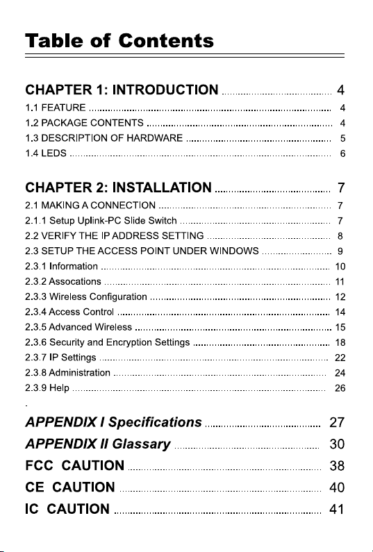
1.3 Description of Hardware
The following figures show the back panels of this Access
Point:
Reset Button
While the user has the trouble of negotiation with
WirelessLAN, pressing the Reset button for system
refresh, pressing the Reset button for system reset to
default settings.
LAN Ports
For linking computers or other Ethernet devices, e.g. a
hub/switch
Uplink/PC Switch
For connect to the Ethernet port of hub/switch,select the
switch to ” Uplink”. If not, switch to “PC”.
Power (DC 5V)
Used to connect the external power adapter supplied with
the Access Point.
be used.
Note that only the supplied adapter should
5
Page 6
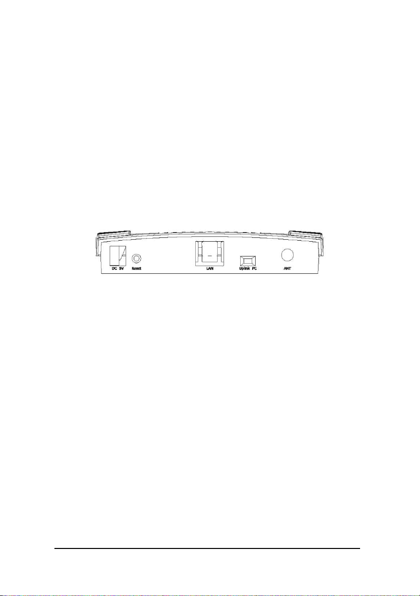
1.4 LEDs
The LEDs are indicators of switch activity and performance.
Table 1 shows the location of the LEDs. You can check each
connection by viewing the port status indicators shown in the
following table.
LED Status Description
Power Green, On Power is supplied to the device
Off Power is disconnected
WLAN Green, On WLAN On
Blinking transmitting data to the wireless LAN
Link/Activity from the Access Point
Off No data transferred
LAN Green, On Good Link
Link/Act Blinking Receiving/transmitting data at 100M
Table 1: LEDs Indicators
6
Page 7

Chapter 2: Installation
2.1 Making a Connection
1. Connect to a hub/switch — Use a standard Ethernet
RJ-45 cable.
2. Check the “Link/Act” LED of “LAN” port on front
panel, it must be on.
If not, to ensure that the cable is connected
properly.
3. Connect the power adapter.
Attention:
1. The cable distance between the Router and PC/hub/
Switch should not exceed 100 meters.
2. Make sure the wiring is correct. In10Mbps
operation, Category 3/4/5 cable can be used for
connection. To reliably operate your network at
100Mbps, you must use Category 5 cable, or better
Data Grade.
2.1.1 Setup Uplink-PC slide switch
1. For connecting to a hub/switch, select the switch to
“Uplink”.
2. For connecting to a PC, select the switch to “PC”.
7
Page 8
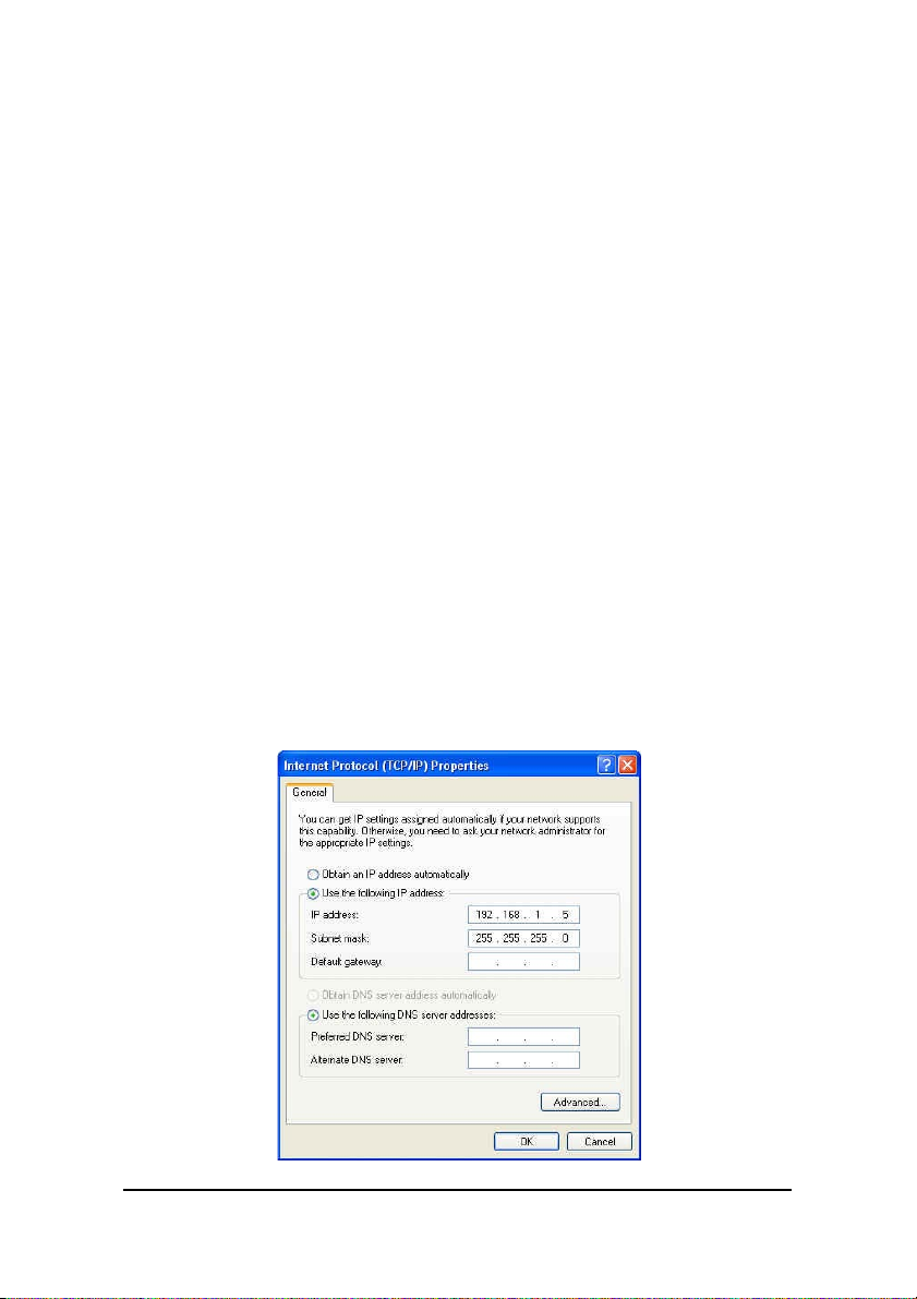
2.2 Verify the IP address setting
Your need to configure your PC’ s network settings to an IP
address. Computer use IP addresses to communicate with
each other across a network, such as the Internet.
1. From the taskbar, click the Start button, select
Settings > Control Panel. From there, double-click
the Network connections icon.
2. Right click the Local Area Connection icon
Properties , select the
cable Ethernet adapter. Then, click the Properties
button.
3. Click the IP Address tab page, select USE the
following IP address, type
1.254
( but, 192.168.1.240 for this Access Point use)
in the IP Address field and
Subnet Mask field, then click OK button.
TCP/IP
line for the appli-
192.168.1.1~192.168.
255.255.255.0
in the
8
Page 9
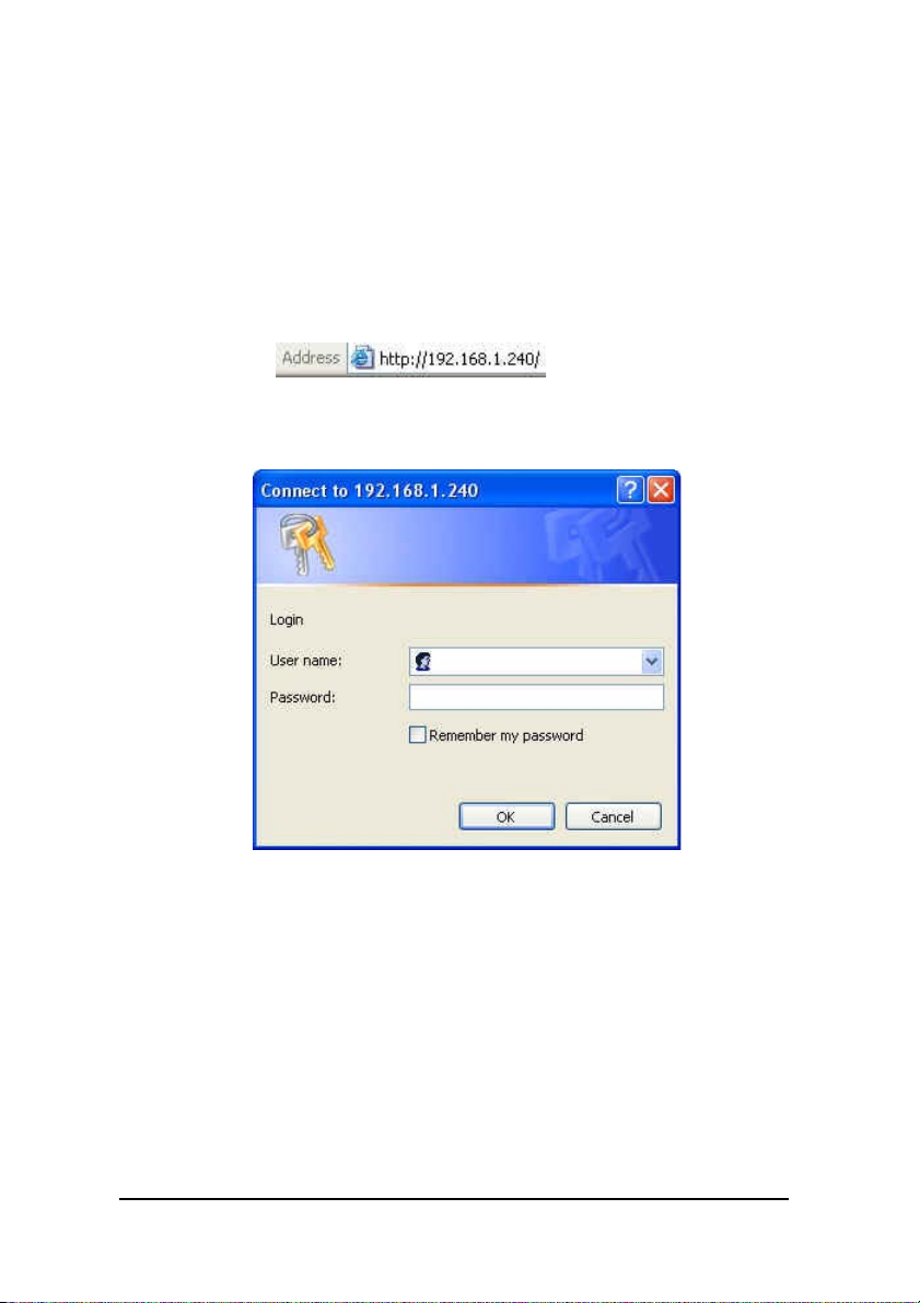
2.3 Setup the Access Point under Windows
Start Setup...
1. After getting the correct connection, start the web
browser
and type 192.168.1.240 in the address field. Press
Enter.
2. Enter the factory default
User name field and Password
field are blank and click OK button.
9
Page 10
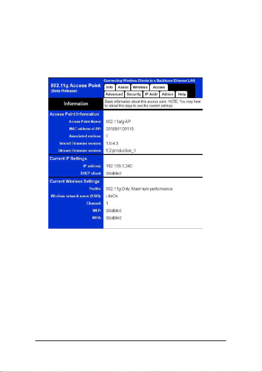
2.3.1 Information
Basic information about this access point. NOTE: You may
have to reload this page to see the current settings.
Figure 1: Information
10
Page 11
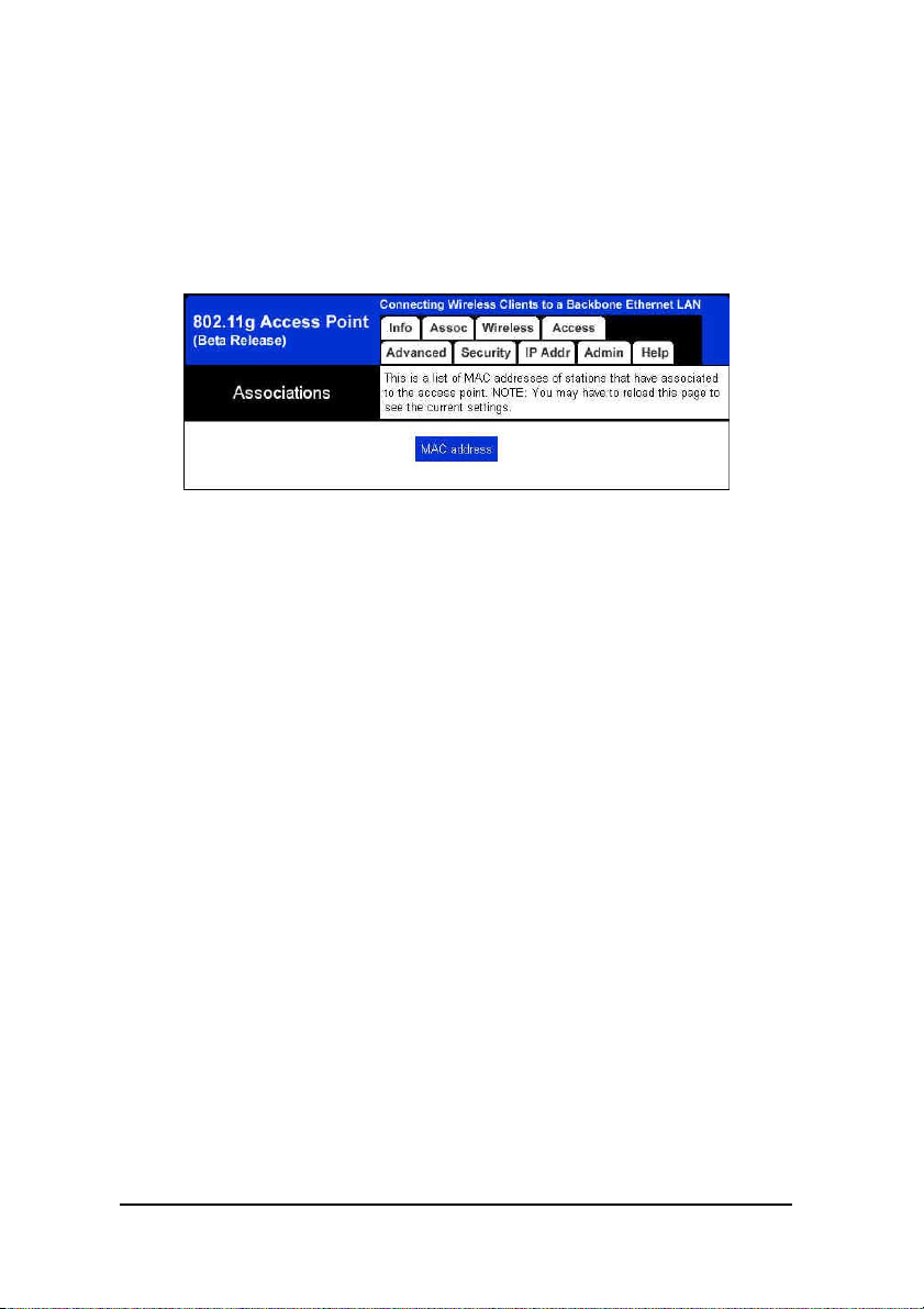
2.3.2 Associations
This is a list of MAC addresses of stations that have associated to the access point. NOTE: You may have to reload this
page to see the current settings.
Figure 2: Associations
11
Page 12
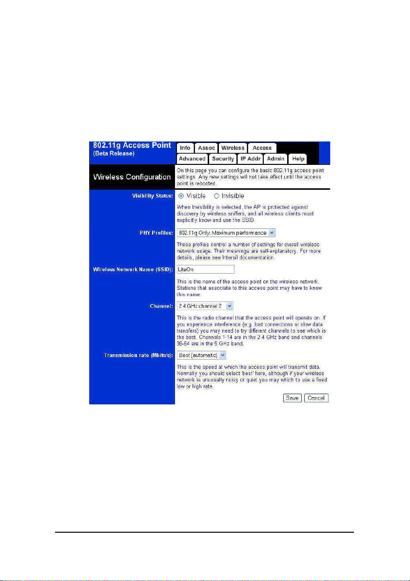
2.3.3 Wireless Configuration
On this page you can configure the basic 802.11g access
point settings. Any new settings will not take effect until the
access point is rebooted.
Figure 3: Wireless Configuration
Visibility Status
When Invisibility is selected, the AP is protected
against discovery by wireless sniffers, and all wireless
clients must explicitly know and use the SSID.
PHY Profiles
These profiles control a number of settings for
12
Page 13

overall wireless network usage. Their meanings are
self-explanatory. For more details, please see Intersil
documentation.
Wireless Network Name (SSID)
This is the name of the access point on the wireless
network. Stations that associate to this access point
may have to know this name.
Channel
IThis is the radio channel that the access point will
operate on. If you experience interference (e.g. lost
connections or slow data transfers) you may need
to try different channels to see which is the best.
Channels 1-11 are in the 2.4 GHz band.
Transmission rate (Mbits/s)
This is the speed at which the access point will
transmit data. Normally you should select ‘best’
here, although if your wireless network is unusually
noisy or quiet you may which to use a fixed low or
high rate.
13
Page 14

2.3.4 Access Control
On this page you can enable Access Control. If enabled, only
the MAC addresses entered into the ‘MAC address’ boxes are
allowed to associate to this AP. Note that you can cut and
paste the addresses from the ‘Station List’ page into the MAC
address boxes. These changes are effective immediately.
Figure 4: Access Control
14
Page 15

2.3.5 Advanced Wireless
On this page you can configure the advanced 802.11g
access point settings. Any new settings will not take effect
until the access point is rebooted.
Figure 5: Advanced Wireless
Maximum associated stations
This the maximum number of wireless stations
that can be associated at any one time.
15
Page 16

Fragmentation threshold
Transmitted wireless packets larger than this size
will be fragmented to maintain performance in noisy
wireless networks.
RTS threshold
Transmitted wireless packets larger than this size
will use the RTS/CTS protocol to (a) maintain
performance in noisy wireless networks and (b)
prevent hidden nodes from degrading performance.
Beacon period
Access point beacons are sent out periodically.
This is the number of milliseconds between each
beacon.
DTIM interval
This is the number of beacons per DTIM (Delivery
Traffic Indication Message), e.g. ‘1’ means send a
DTIM with each beacon, ‘2’ means with every 2nd
beacon, etc.
Maximum burst time
This is also known as PRISM Nitro (tm)
technology. The technology uses fully standardscompliant methods that eliminate collisions in mixedmode networks, while greatly increasing the
performance of both pure 802.11g and mixed 802.
11b/g networks. The setting is for the amount of
time the radio will be reserved to send data without
requiring an ACK. This number is in units of
microseconds. A typical value would be 650
microseconds. When this number is zero, bursting is
16
Page 17

disabled.
Enable PSM buffer
Turn this on to enable support for stations in power
save mode.
17
Page 18

2.3.6 Security and Encryption Settings
On this page you can set the 802.11g security and encryption options. Any new settings will not take effect until the
access point is rebooted.
Figure 6-1: Security and Encryption Settings(1)
18
Page 19

Figure 6-2: Security and Encryption Settings(2)
WPA configuration
Enable WPA Authenticator to require stations to use
high grade encryption and authentication.
WPA Enable.
PSK Pass-phrase: Leave blank if stations will be sup-
plied a key by the 1X Authentication Server. Choose a
pass-phrase between 8 and 63 characters.
WPA Multicast Cipher Type: Currently TKIP is the
only permitted setting.
19
Page 20

WPA Pairwise Cipher Type: Currently TKIP is the only
permitted setting.
WPA Group Key Update Interval.
802.1X configuration
When 802.1X authentication is enabled then the AP
will authenticate clients via a remote RADIUS server.
802.1X Enable.
Authentication timeout(mins).
RADIUS server IP address.
RADIUS server port number.
RADIUS server shared secret.
MAC Address Authentication.
WEP configuration
WEP is the wireless encryption standard. To use it
you must enter the same key(s) into the access point
and the wireless stations. For 64 bit keys you must enter
10 hex digits into each key box. For 128 bit keys you
must enter 26 hex digits into each key box. A hex digit is
either a number from 0 to 9 or a letter from A to F. If
you leave a key box blank then this means a key of all
zeros.
Enable WEP : Check this box to enable WEP. For the
most secure use of WEP, also select “Deny Unencrypted
Data” and set Authentication to “Shared Key” when WEP
is enabled.
WEP key lengths: Select the key size. This length
applies to all keys.
WEP key.
Default WEP key to use: Select the key to be used
20
Page 21

as the default key. Data transmissions are always encrypted using the default key. The other keys can only
be used to decrypt received data.
Deny unencrypted data: Select this to require peers
to use encryption. This is only effective when WEP is
enabled
Authentication: ‘Open’ allows anyone to authenti-
cate to this access point. ‘Shared key’ allows only stations that know the key(s) to authenticate. ‘Both’ allows
a station to use either mode.
21
Page 22

2.3.7 IP Settings
On this page you can configure the IP address used by the
Web server running on this access point. For “static” mode, the
IP address settings are given here. For “DHCP” mode, these settings are supplied by a DHCP server on your network. Any new
IP settings will not take effect until the access point is rebooted.
Figure 7: IP Settings
IP Address Mode
Select ‘DHCP’ to get the IP settings from a DHCP
server on your network. Select ‘Static’ to use the IP
settings specified on this page.
22
Page 23

Default IP Address
Type the IP address of your Access Point.
Default subnet mask
The subnet mask specifies the network number
portion of an IP address. The factory default is 255.255.
255.0.
Default gateway
This is the IP address of the gateway that connects
you to the internet.
Access point name
This is the name that the access point will use to
identify itself to external configuration and IP-addressfinding programs. This is not the same as the SSID. It is
okay to leave this blank if you are not using these
programs.
23
Page 24

2.3.8 Administration
On this page you can change the password, reboot the access
point, or reset all settings to their factory defaults. If you have
changed any settings it is necessary to reboot the access point
for the new settings to take effect.
Figure 8: Administration
User name
This is the user name that you must type when
logging in to these web pages.
administrator password
This is the password that you must type when
logging in to these web pages. You must enter the same
24
Page 25

password into both boxes, for confirmation.
Commands
Reboot access point.
Reset to factory defaults.
Upgrade firmware
The upload may take up to 60 seconds.
25
Page 26

2.3.9 Help
This is where some helpful information will go. There is
nothing here right now.
Figure 9: Help
26
Page 27

Appendix I Specifications
Standard support
IEEE802.3, IEEE802.3u, IEEE802.11b, IEEE802.11g
Interface
Wireless IEEE 802.11b/g
One 10/100 Mbps RJ-45 port
Max. Band width
Ethernet:
Full Duplex: 200Mbps (100BaseTX), 20 Mbps(10BaseT)
Half Duplex: 100Mbps (100BaseTX), 10 Mbps(10BaseT)
Wireless: 1, 2, 5.5, 6, 9, 1 1, 12, 24, 36, 48, 54 Mbps, Auto
Fall-Back
SDRAM 1Mbit
Flash 4Mbit
Diagnostic LEDs
Unit: Power (Green)
WLAN: 100M Link/Activity (Green)
LAN: 100M Link/Act (Green)
Wireless Radio
Data Rate:1, 2, 5.5, 6, 9, 11, 12, 24, 36, 48, 54 Mbps
Signal Frequency: 2.4Ghz to 2.5Ghz OFDM with BPSK, QPSK,
16QAM, 64QAM, DBPSK, DQPSK, CCK
Encryption: 64bit and 128bit WEP data encryption
Channel:
America/FCC: 2.412~2.462 GHz (11 channels)
Europe CE/ETSI: 2.412~2.472 GHz (13 channels)
Japan: 2.412~2.484 GHz (14 channels)
France: 2.457~2.472 GHz(4 channels)
Spain: 2.457~2.462 GHz (2 channels)
RF Power Output: 16 dBm@ 11Mbps/ 12dBm @54 Mbps
(typical)
27
Page 28

Receiver Sensitivity: 54Mbps OF DM, 10% PER, -68dBm 11Mbps
CCK, 8% PER, -84dBm
Wireless Setting
− SSID
− Channel Selection
− Tra nsmission Rate (Best, 54, 48, 36, 24, 18, 12, 11, 9, 6, 5.5,
2, 1) in Mbps
− Intersil PHY profile s
802.11g Max Performance,
802.11g only
802.11b/g Mixed
802.11b/g Mixed with Long Preamble
802.11b for Wi-Fi certification
802.11b only
− Fragment Threshold
− RTS Threshold
Wireless Security
WEP setting
− WEP Enabled (On or Off)
− WEP key Length(64-bit, 128 -bit)
− Default WEP key to use (1-4)
− WEP key (10 or 26 hex digits)
− Deny unencrpted data (On or Off)
− Authentication (Open, Shared Key, Both)
WPA setting
− WPA Enabled (On or Off)
− PSK (up to 63 charactersof text)
− WPA Muticast Cipher Type (TKIP-WPA, None)
− WPA Pairwise Cipher Type (TKIP-WPA, None)
Software / Firmware
− AP a nd Bridge mode support (Need different f irmware)
− DHCP Client
28
Page 29

− WPA Support (Bridge mode support WPA PSK only)
− MAC Cloning (WLAN Card, Ethernet Client)
− Web-based configuration via popular browser (MS IE,
Netscape...)
− Firmware download and upgra de via web server
− Reset to default by web server or hardware button
Forwarding Mode store and foreard
Antenna Gain Max 1.91 dB
29
Page 30

Appendix II Glossary
802.11 standard
802.11, or IEEE 802.11, is a type of radio technology used for
wireless local area networks (WLANs). It is a standard that has
been developed by the IEEE (Institute of Electrical and Electronic Engineers), http://standards.ieee.org. The IEEE is an international organization that develops standards for hundreds of
electronic and electrical technologies. The organization uses a
series of numbers, like the Dewey Decimal system in libraries, to
differentiate between the various technology families.
The 802 subgroup (of the IEEE) develops standards for local
and wide area networks with the 802.11 section reviewing and
creating standards for wireless local area networks.
Wi-Fi , 802.11, is composed of several standards operating in
different radio frequencies: 802.11b is a standard for wireless
LANs operating in the 2.4 GHz spectrum with a bandwidth of 11
Mbps.
Another standard, 802.11g, is for WLANS operating in the 2.4 GHz
frequency but with a bandwidth of 54 Mbps.
30
Page 31

802.11b
International standard for wireless networking that operates
in the 2.4 GHz frequency range (2.4 GHz to 2.4835 GHz) and
provides a throughput of up to 11 Mbps. This is a very commonly
used frequency. Microwave ovens, cordless phones, medical and
scientific equipment, as well as Bluetooth devices, all work within
the 2.4 GHz frequency band.
802.11g
Similar to 802.11b, but this standard provides a throughput of
up to 54 Mbps. It also operates in the 2.4 GHz frequency band
but uses a different radio technology in order to boost overall
bandwidth.
Access point
A wireless LAN transceiver or “base station” that can connect a
wired LAN to one or many wireless devices. Access points can
also bridge to each other.
There are various types of access points and base stations
used in both wireless and wired networks. These include bridges,
hubs, switches, routers and gateways. The differences between
them are not always precise, because certain capabilities associated with one can also be added to another. For example, a
router can do bridging, and a hub may also be a switch. But
they are all involved in making sure data is transferred from one
location to another.
A bridge connects devices that all use the same kind of protocol.
A router can connect networks that use differing protocols. It
also reads the addresses included in the packets and routes
them to the appropriate computer station, working with any other
routers in the network to choose the best path to send the packets on. A wireless hub or access point adds a few capabilities
31
Page 32

such as roaming and provides a network connection to a variety
of clients, but it does not allocate bandwidth. A switch is a hub
that has extra intelligence: It can read the address of a packet
and send it to the appropriate computer station. A wireless gateway is an access point that provides additional capabilities such
as NAT routing, DHCP, firewalls, security, etc.
AES (Advanced Encryption Standard)
A chip-based security, has been developed to ensure the
highest degree of security and authenticity for digital information,
wherever and however communicated or stored, while making
more efficient use of hardware and/or software than previous
encryption standards. It is also included in IEEE 802.11i standard.
Compared with AES, TKIP is a temporary protocol for replacing
WEP security until manufacturers implement AES at the hardware level.
DHCP
Dynamic Host Configuration Protocol. This protocol automatically configures the TCP/IP settings of every computer on your
home network.
Encryption key
An alphanumeric (letters and/or numbers) series that enables
data to be encrypted and then decrypted so it can be safely
shared among members of a network. WEP uses an encryption
key that automatically encrypts outgoing wireless data. On the
receiving side, the same encryption key enables the computer to
automatically decrypt the information so it can be read.
Ethernet
A standard for computer networks. Ethernet networks are con-
32
Page 33

nected by special cables and hubs, and move data around at up
to 100 million bits per second (Mbps).
ESSID
The identifying name of an 802.11 wireless network. When
you specify your correct ESSID in your client setup you ensure
that you connect to your wireless network rather than another
network in range. (See SSID.) The ESSID can be called by different terms, such as Network Name, Preferred Network, SSID
or Wireless LAN Service Area.
Gateway
In the wireless world, a gateway is an access point with additional software capabilities such as providing NAT and DHCP.
Gateways may also provide VPN support, roaming, firewalls,
various levels of security, etc.
IEEE802.11
A set of specifications for LANs from The Institute of Electrical
and Electronics Engineers (IEEE). Most wired networks conform to 802.3, the specification for CSMA/CD based Ethernet
networks or 802.5, the specification for token ring networks.
802.11 defines the standard for wireless LANs encompassing
three incompatible (non-interoperable) technologies: Frequency
Hopping Spread Spectrum (FHSS), Direct Sequence Spread
Spectrum (DSSS) and Infrared. WECA’s focus is on 802.11b, an
11 Mbps high-rate DSSS standard for wireless networks.
IP Address
IP stands for Internet Protocol. An IP address consists of a
series of four numbers separated by periods, that identifies an
single, unique Internet computer host. Example: 192.34.45.8.
33
Page 34

ISP Gateway Address (see ISP for definition).
The ISP Gateway Address is an IP address for the Internet
router located at the ISP’s office. This address is required only
when using a cable or DSL modem.
ISP
Internet Service Provider. An ISP is a business that provides
connectivity to the Internet for individuals and other businesses
or organizations.
LAN
Local Area Network. A LAN is a group of computers and devices connected together in a relatively small area (such as a
house or an office). Your home network is considered a LAN.
MAC
Every wireless 802.11 device has its own specific MAC address hard-coded into it. This unique identifier can be used to
provide security for wireless networks. When a network uses a
MAC table, only the 802.11 radios that have had their MAC addresses added to that network’s MAC table will be able to get
onto the network.
MAC Address
MAC stands for Media Access Control. A MAC address is the
hardware address of a device connected to a network.
Peer-to-peer network
A wireless or wired computer network that has no server or
central hub or router. All the networked PCs are equally able to
act as a network server or client, and each client computer can
talk to all the other wireless computers without having to go
through an access point or hub. However, since there is no central base station to monitor traffic or provide Internet access, the
34
Page 35

various signals can collide with each other, reducing overall
performance.
SSID
A 32-character unique identifier attached to the header of
packets sent over a WLAN that acts as a password when a mobile device tries to connect to the BSS. (Also called ESSID.) The
SSID differentiates one WLAN from another, so all access points
and all devices attempting to connect to a specific WLAN must
use the same SSID. A device will not be permitted to join the
BSS unless it can provide the unique SSID. Because an SSID can
be sniffed in plain text from a packet, it does not supply any
security to the network. An SSID is also referred to as a Network
Name because essentially it is a name that identifies a wireless
network.
Subnet Mask
A subnet mask, which may be a part of the TCP/IP information provided by your ISP, is a set of four numbers configured
like an IP address. It is used to create IP address numbers used
only within a particular network (as opposed to valid IP address
numbers recognized by the Internet.
TCP/IP
Transmission Control Protocol/Internet Protocol. This is the
standard protocol for data transmission over the Internet.
TKIP
The TKIP (Temporal Key Integrity Protocol), pronounced teekip, is part of the IEEE 802.11i encryption standard for wireless
LANs. TKIP is the next generation of WEP used to secure 802.11
wireless LANs.TKIP provides per-packet key mixing, a message
35
Page 36

integrity check and a re-keying mechanism, thus fixing the flaws
of WEP.
WAN
A wide area network (WAN) is a geographically dispersed
telecommunications network. The term distinguishes a broader
telecommunication structure from a local area network. A wide
area network may be privately owned or rented, but the term
usually connotes the inclusion of public (shared user) networks.
An intermediate form of network in terms of geography is a
metropolitan area network .
WEP
WEP (Wired Equivalent Privacy) is 802.11’s optional encryption standard implemented in the MAC layer that most radio
network interface card (NIC) and access point vendors support.
Basic wireless security provided by Wi-Fi. In some instances,
WEP may be all a home or small-business user needs to protect
wireless data. WEP is available in 40-bit (also called 64-bit), or in
108-bit (also called 128-bit) encryption modes. As 108-bit encryption provides a longer algorithm that takes longer to decode,
it can provide better security than basic 40-bit (64-bit) encryption.
Wi-Fi
An interoperability certification for wireless local area network (LAN) products based on the Institute of Electrical and
Electronics Engineers (IEEE) 802.11 standard.
WLAN
Also referred to as LAN. A type of local-area network that uses
high-frequency radio waves rather than wires to communicate
between nodes.
36
Page 37

WPA
WPA is a standards-based, interoperable security specification
that utilizes Temporal Key Integrity Protocol to provide improved over-the-air encryption of wireless data.
37
Page 38

Page 39

In order to maintain compliance with the FCC RF exposure guidelines, this
equipment shouldbe installed and operated with minimum distance 20cm
between the radiator and your body.Use only with supplied antenna.
Unauthorized antenna, modification, or attachments could damage the
transmitter and may violate FCC regulations.
Page 40

Page 41

 Loading...