

Page 1
Page 1/14
USER MANUAL
Wi-Fi (11a/b/g/n/ac 2Tx2R) + BT (V4.1 LE) SDIO Combo Module
WCBN4503M
Marvell 88w8897
Version 1.3
Change History
Revision
Date
Author
Change List
Version 1.0
2015/05/17
Ben J. Chen
Preliminary
Version 1.1
2015/07/01
Ben J. Chen
Update Transmit Output Power
Update
Pin Assignment
- Change Pin13 to NC, using internal 1.8V
Update Connector SPEC
Version 1.2
2015/07/09
Ben J. Chen
Update Power Consumption
Version 1.
3
2015/07/22
Ben J. Chen
Update Antenna SPEC
- Remove Sponge and Heat Shrink tubing
* This document contains confidential proprietary information and is property of LTC. The contents of
this document should not be disclosed to unauthorized persons without the written consent of LTC.
Page 2
Page 2/14
USER MANUAL
Wi-Fi (11a/b/g/n/ac 2Tx2R) + BT (V4.1 LE) SDIO Combo Module
WCBN4503M
Marvell 88w8897
Version 1.3
Networking B.U.
Lite-on Technology Corporation
4F, No. 90, Chien I Rd.,
Chung Ho, New Taipei City 235, Taiwan, R.O.C.
Customer Approval: (Signature)
(Title)
(Company)
(Date)
(Please Sign Back by FAX. For Confirming the Spec Only, not an Official Agreement for OEM/ODM Business)
Page 3
Page 3/14
CONTENT
PRODUCT FEATURES ....................................................................................................................4
BT FEATURE: ......................................................................................................................................... 4
WI-FI FEATURE:.....................................................................................................................................4
COMMON FEATURE................................................................................................................................ 4
PRODUCT SPECIFICATIONS ........................................................................................................ 5
MAIN CHIPSET ....................................................................................................................................... 5
FUNCTIONAL SPECIFICATIONS ............................................................................................................... 5
RECOMMENDED OPERATION CONDITIONS..........................................................................7
PIN ASSIGNMENT............................................................................................................................ 8
CONNECTOR SPEC ......................................................................................................................... 8
POWER-UP SEQUENCE TIMING ................................................................................................. 9
MECHANICAL .................................................................................................................................. 9
ANTENNA SPEC ............................................................................................................................. 10
WI-FI ANTENNA (Q’TY: 2PCS) ............................................................................................................. 10
WI-FI ANTENNA PHOTO....................................................................................................................... 11
BT ANTENNA(Q’TY: 1PCS) ..................................................................................................................12
BT ANTENNA PHOTO ........................................................................................................................... 13
EEPROM INFORMATION ............................................................................................................ 14
BT........................................................................................................................................................ 14
WI-FI ................................................................................................................................................... 14
ENVIRONMENTAL ........................................................................................................................ 14
OPERATING .......................................................................................................................................... 14
STORAGE..............................................................................................................................................14
Page 4
Page 4/14
PRODUCT FEATURES
BT FEATURE:
l Bluetooth V4.1 LE system
Backwards compatible with BT version of 1.1, 1.2, 2.0, 2.1and 3.0+HS
l Support Dual-mode Bluetooth
l BT using SDIO interface
l BT transmission speed including 1M (GFSK), 2M (π/4-DQPSK) and 3Mbps
(8DPSK) EDR and up to 54Mbps (Physical Rate) High Speed operations
l Support for Simple Pairing (SP) and Enhanced Inquiry Response (EIR) function
l Support master and slave piconet and scatternet
l Adaptive Frequency Hopping (AFH) using Packet Loss Rate (PLR)
l Enhanced low power scan mode
WI-FI FEATURE:
l Operate at ISM frequency Band (2.4/5GHz)
l IEEE Standards Support, 802.11a,802.11b, 802.11g, 802.11n and 802.11ac
l Support for both 20 MHz/40 MHz channel width in 2.4GHz and 20 MHz/40
MHz/80MHz channel width in 5GHz
l Support SDIO 3.0 interface, 4-bit SDIO transfer modes at full clock range up to
208MHz
l Enterprise level security supporting: WEP, WPA, WPA2, WAPI
l Dual-stream IEEE 802.11n support for 20MHz and 40MHz channels provides
PHY layer rates up to 300Mbps
l Dual-stream IEEE 802.11ac support for 80MHz channels provides PHY layer
rates up to 867Mbps
l Support Wi-Fi Direct
l Support Wake On WLAN
COMMON FEATURE
l Support for BT & WLAN Co-existence
l Support Linux OS based
l RoHS compliance
l Low Halogen compliance
Page 5
Page 5/14
PRODUCT SPECIFICATIONS
MAIN CHIPSET
Marvell 88w8897
FUNCTIONAL SPECIFICATIONS
BT Function
Standard
Bluetooth V
4.1 LE
Bus Interface
SDIO
Data Rate
1 Mbps, 2Mbps and Up to
3Mbps
Modulation Scheme
GFSK, π/4
-DQPSK and 8-DPSK
Frequency Range
2.402~2.480 GHz
Transmit Output Power
+4
≤ Output Power ≤ +10 ; Class I Device
Receive
r Sensitivity
< 0.1% BER at
-80dBm
Wi
-Fi Function
Standard
IEEE802.11a; IEEE802.11b; IEEE 802.11g; IEEE 802.11n,
IEEE 802.11ac
Bus Interface
SDIO
3.0
Data Rate
802.11b:
11, 5.5, 2, 1 Mbps
802.11
a/g:
54, 48, 36, 24, 18, 12, 9, 6 Mbps
802.11n:
MCS 0 to 15 for HT20MHz
MCS 0 to 15 for HT40MHz
802.11
ac:
MCS 0 to 8 for HT20MHz
MCS 0 to 9 for HT40MHz
MCS 0 to 9 for HT80MHz
Media Access Control
CSMA/CA with ACK
Modulation Techniques
802.11b:
CCK, DQPSK, DBPSK
802.11
a/g:
64QAM, 16QAM, QPSK, BPSK
802.11n
:
64QAM, 16QAM, QPSK, BPSK
802.11
ac:
256QAM, 64QAM, 16QAM, QPSK, BPSK
Page 6
Page 6/14
Network Architecture
Ad-hoc mode (Peer-to-Peer)
Infrastructure mode
Operation Channel
2.4GHz
11: (Ch. 1-11) – United States
13: (Ch. 1-13) – Europe
14: (Ch. 1-14) – Japan
5GHz
12: United States
19: Europe
8: Japan
Frequency Range
802.11bg
2.412 ~ 2.462 GHz
802.11
a
5.15 ~ 5.825 GHz
Transmit Output
Power
– 2x2
(Tolerance:
Ʋ1.5
dBm)
802.11a:
14 dBm@6Mbps
14 dBm@54Mbps
802.11b:
15 dBm@1Mbps
15 dBm@11Mbps
802.11g:
14 dBm@6Mbps
14 dBm@54Mbps
802.11n
(2.4GHz):
20MHz:
13 dBm@MCS0
13 dBm@MCS7
40MHz:
13 dBm@MCS0
13 dBm@MCS7
802.11n
(5GHz):
20MHz:
11 dBm@MCS0
11 dBm@MCS7
40MHz:
10 dBm@MCS0
10 dBm@MCS7
802.1
1ac:
20MHz:
11 dBm@MCS0
11 dBm@MCS8
40MHz:
10 dBm@MCS0
10
dBm@MCS
8
10 dBm@MCS9
80MHz:
8 dBm@MCS0
8 dBm@MCS8
8 dBm@MCS9
Receive
r Sensitivity
802.11a:
-86 dBm@6Mbps
-70 dBm@54Mbps
802.11b:
-88 dBm@1Mbps
-82 dBm@11Mbps
802.11g:
Page 7
Page 7/14
-86 dBm@6Mbps
-70 dBm@54Mbps
802.11n
(2.4GHz):
20MHz
-86 dBm@MCS0
-69 dBm@MCS7
40MHz
-83 dBm@MCS0
-66 dBm@MCS7
802.11n
(5GHz):
20MHz
-84 dBm@MCS0
-67 dBm@MCS7
40MHz
-81 dBm@MCS0
-64 dBm@MCS7
802.1
1ac:
20MHz
-64 dBm@MCS8
40MHz
-62 dBm@MCS8
-59 dBm@MCS9
80MHz
-59 dBm@MCS8
-54 dBm@MCS9
Security
WPA, WPA2, WEP 64bit & 128bit, IEEE 802.1X, IEEE
802.11i
Common Function
Operating Voltage
3.3
V ±10% I/O supply voltage
OS
Supported
Linux Based
Power Consumption
Mode
Average
Peak
2.4G
5G
2.4G
5G
TX
550mA
750mA
800mA
900mA
RX
110mA
180mA
Idle
90mA
Deep
Sleep
1mA
Antenna Type
Triple
U.FL connectors for plugging external antenna
RECOMMENDED OPERATION CONDITIONS
Symbol
Parameter Min
Typ
Max
Units
AVDD33
3.3V analog power supply
2.97
3.3
3.63
V
AVDD18
1.8V analog power supply
1.71
1.8
1.98
V
VIO
1.8V power supply for host interface
1.62
1.8
1.98
V
3.3V power supply for host interface
2.97
3.3
3.63
V
Page 8

Page 8/14
PIN ASSIGNMENT
Pin.
Pin Define
Description
Status
1
GND
Ground
YES
2
GND
Ground
YES
3
SDIO_Data1
SDIO Data Line1
YES
4
SDIO_Data2
SDIO Data Line2
YES
5
SDIO_Data0
SDIO Data Line0
YES
6
SDIO_Data3
SDIO Data Line3
YES
7
SDIO_CMD
SDIO Command Input
YES
8
WL/BT_HOST_
WAKE#
Device
wake up Host, Low Active
YES
9
SDIO_CLK
SDIO Clock Input
YES
10
GND
Ground
YES
11
PDn#
Active Low to Power-Down WLAN
YES
12
GND
Ground
YES
13
+1.8V
1.8V power supply for VIO_SD
NC
14
+3.3V
3.3V power supply
YES
CONNECTOR SPEC
Page 9

Page 9/14
POWER-UP SEQUENCE TIMING
MECHANICAL
Page 10

Page 10/14
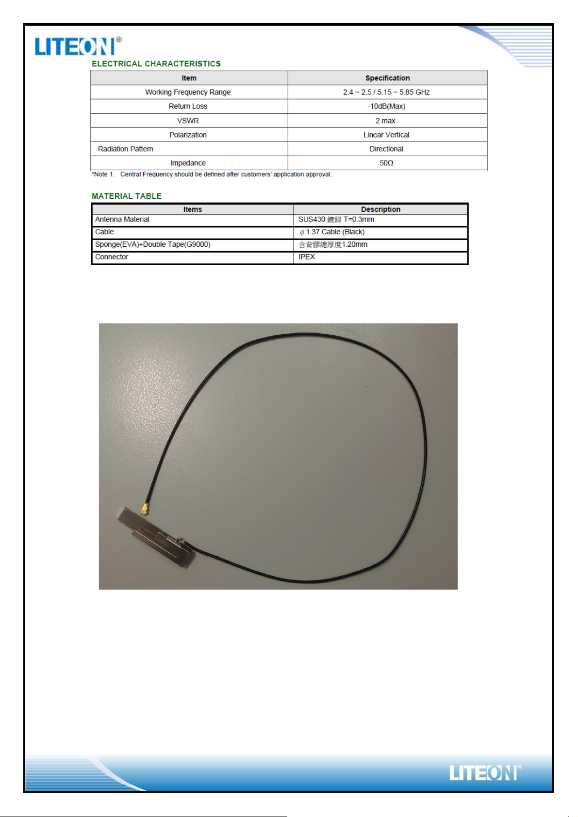
ANTENNA SPEC
Wi-Fi Antenna (Q’ty: 2pcs)
Page 11
Page 11/14
WI-FI ANTENNA PHOTO
Page 12

Page 12/14
BT Antenna(Q’ty: 1pcs)
Page 13

Page 13/14
BT ANTENNA PHOTO
Page 14

Page 14/14
BLOCK DIAGRAM
EEPROM INFORMATION
BT
Vendor ID
0xTBD
Product
ID
0xTBD
WI-FI
Region C
ode
FCC SKU
2.4G: CH1-11
5G: U-NII-1, U-NII-3
CC=0x10
Vendor ID
0xTBD
Device ID
0xTBD
ENVIRONMENTAL
OPERATING
Operating Temperature: 0 to 70 °C (32 to 158°F)
Relative Humidity: 5-90% (non-condensing)
STORAGE
Temperature: -40 to 80 °C (-40 to 176 °F)
Relative Humidity: 5-95% (non-condensing)
Page 15

FCC Statement:
Federal Communication Commission Interference Statement
This equipment has been tested and found to comply with the limits for a Class B digital device, pursuant
to Part 15 of the FCC Rules. These limits are designed to provide reasonable protection against harmful
interference in a residential installation. This equipment generates, uses and can radiate radio frequency
energy and, if not installed and used in accordance with the instructions, may cause harmful interference
to radio communications. However, there is no guarantee that interference will not occur in a particular
installation. If this equipment does cause harmful interference to radio or television reception, which can
be determined by turning the equipment off and on, the user is encouraged to try to correct the
interference by one of the following measures:
˗ġReorient or relocate the receiving antenna.
˗ġIncrease the separation between the equipment and receiver.
˗ġConnect the equipment into an outlet on a circuit different from that to which the receiver is
connected.
˗ġConsult the dealer or an experienced radio/TV technician for help.
FCC Caution: Any changes or modifications not expressly approved by the party responsible for
compliance could void the user’s authority to operate this equipment.
This device complies with Part 15 of the FCC Rules. Operation is subject to the following two
conditions: (1) This device may not cause harmful interference, and (2) this device must accept any
interference received, including interference that may cause undesired operation.
For product available in the USA/Canada market, only channel 1~11 can be operated. Selection of other
channels is not possible.
This device and its antenna(s) must not be co•located with any other transmitters except in
accordance with FCC multi•transmitter product procedures.
Refering to the multi•transmitter policy, multiple•transmitter(s) and module(s) can be operated
simultaneously without C2PC.
IMPORTANT NOTE:
FCC Radiation Exposure Statement:
This equipment complies with FCC radiation exposure limits set forth for an uncontrolled environment.
This equipment should be installed and operated with minimum distance 20 cm between the radiator &
your body.
Page 16

IMPORTANT NOTE:
This module is intended for OEM integrator. The OEM integrator is responsible for the
compliance to all the rules that apply to the product into which this certified RF module is
integrated.
Additional testing and certification may be necessary when multiple modules are used.
20 cm minimum distance has to be able to be maintained between the antenna and the users for the host
this module is integrated into. Under such configuration, the FCC radiation exposure limits set forth for an
population/uncontrolled environment can be satisfied.
Any changes or modifications not expressly approved by the manufacturer could void the user's authority
to operate this equipment.
USERS MANUAL OF THE END PRODUCT:
In the users manual of the end product, the end user has to be informed to keep at least 20 cm separation
with the antenna while this end product is installed and operated. The end user has to be informed that
the FCC radio•frequency exposure guidelines for an uncontrolled environment can be satisfied. The end
user has to also be informed that any changes or modifications not expressly approved by the
manufacturer could void the user's authority to operate this equipment. If the size of the end product is
smaller than 8x10cm, then additional FCC part 15.19 statement is required to be available in the users
manual: This device complies with Part 15 of FCC rules. Operation is subject to the following two
conditions: (1) this device may not cause harmful interference and (2) this device must accept any
interference received, including interference that may cause undesired operation.
LABEL OF THE END PRODUCT:
The final end product must be labeled in a visible area with the following " Contains TX FCC ID: PPQWCBN4503M ". If the size of the end product is larger than 8x10cm, then the following FCC part 15.19
statement has to also be available on the label: This device complies with Part 15 of FCC rules. Operation is
subject to the following two conditions: (1) this device may not cause harmful interference and (2) this
device must accept any interference received, including interference that may cause undesired operation.
OEM/Integrators Installation Manual
The OEM integrator has to be aware not to provide information to the end user regarding how to install or
remove this RF module in the user manual of the end product. The user manual of the end product which
is provided by OEM integrators for end users must include the following information in a prominent
location.
1. To comply with FCC RF exposure compliance requirements, the antenna used for this transmitter must
be installed to provide a separation distance of at least 20 cm from all persons and must not be co- located
or operating in conjunction with any other antenna or transmitter, except in accordance with FCC multiˢ
transmitter product transmitter product procedures.
It is the responsibility of the professional installer to ensure that the system.
2. Only those antennas with same type and lesser gain filed under this FCC ID number can be used with this
device.
3. The regulatory label on the final system must include the statement: “Contains FCC ID: PPQ-
WCBN4503M “.
Page 17

OEM Integrator Checklist
The party below will implement the LITE-ON Module in host systems in accordance with the instructions
specified in this document and the documents referenced herein.
1. The OEM integrator will ensure the Module is integrated in a host systems using only the approved
antenna model(s) described in this document.
2. The OEM integrator will ensure the antenna placement inside the host system will maintain the
required spacing to end user for RF Exposure compliance, as specified in this document.
3. If other radios are integrated inside the host with the LITE-ON Module, the OEM integrator will contact
its test lab, TCB or LITE-ON to determine if additional FCC compliance evaluation is required to meet FCC
collocation rules.
4. The OEM integrator will ensure end user documentation will contain the specified regulatory wording
and ensure the host system and the Module itself are labeled as specified in this document.
5. The OEM integrator will ensure the Module is programmed in the factory with compliant transmit
power not exceeding the levels specified in this document.
LITE-ON requests that the OEM integrator acknowledge its receipt of this document and the above
instructions. You may contact LITE-ON with any questions concerning this document or the
responsibilities of the OEM integrator.
Page 18

IC Statement:
This device complies with Industry Canada license•exempt RSS standard(s). Operation is subject to the
following two conditions: (1) this device may not cause interference, and (2) this device must accept any
interference, including interference that may cause undesired operation of the device.
Le présent appareil est conforme aux CNR d'Industrie Canada applicables aux appareils radio
exempts de licence. L'exploitation est autorisée aux deux conditions suivantes : (1) l'appareil ne doit pas
produire de brouillage, et (2) l'utilisateur de l'appareil doit accepter tout brouillage radioélectrique subi,
même si le brouillage est susceptible d'en compromettre le
fonctionnement.
For product available in the USA/Canada market, only channel 1~11 can be operated. Selection of other
channels is not possible.
Pour les produits disponibles aux États•Unis / Canada du marché, seul le canal 1 à 11 peuvent être
exploités. Sélection d'autres canaux n'est pas possible.
This device and its antenna(s) must not be co•located with any other transmitters except in
accordance with IC multi•transmitter product procedures.
Refering to the multi•transmitter policy, multiple•transmitter(s) and module(s) can be operated
simultaneously without reassessment permissive change.
Cet appareil et son antenne (s) ne doit pas être co•localisés ou fonctionnement en association avec une
autre antenne ou transmetteur.
The device for operation in the band 5150-5250 MHz is only for indoor use to reduce the
potential for harmful interference to co•channel mobile satellite systems.
les dispositifs fonctionnant dans la bande 5150•5250 MHz sont réservés uniquement pour une utilisation
à l’intérieur afin de réduire les risques de brouillage préjudiciable aux systèmes de satellites mobiles
utilisant les mêmes canaux.
The maximum antenna gain permitted for devices in the band 5725•5850 MHz shall be such that the
equipment still complies with the e.i.r.p. limits specified for point•to•point and
non•point•to•point operation as appropriate.
le gain maximal d’antenne permis (pour les dispositifs utilisant la bande 5725•5850 MHz)
doit se conformer à la limite de p.i.r.e. spécifiée pour l’exploitation point à point et non point à point,
selon le cas.
Dynamic Frequency Selection (DFS) for devices operating in the bands 5250• 5350 MHz,
5470•5600 MHz and 5650•5725 MHz.
Page 19

Sélection dynamique de fréquences (DFS) pour les dispositifs fonctionnant dans les bandes
5250•5350 MHz, 5470•5600 MHz et 5650•5725 MHz.
The maximum antenna gain permitted for devices in the bands 5250•5350 MHz and 5470•5725 MHz shall
be such that the equipment still complies with the e.i.r.p. limit.
le gain maximal d’antenne permis pour les dispositifs utilisant les bandes 5250•5350 MHz et
5470•5725 MHz doit se conformer à la limite de p.i.r.e.
Users should also be advised that high•power radars are allocated as primary users (i.e. priority users) of
the bands 5250•5350 MHz and 5650•5850 MHz and that these radars could cause interference and/or
damage to LE•LAN devices.
De plus, les utilisateurs devraient aussi être avisés que les utilisateurs de radars de haute
puissance sont désignés utilisateurs principaux (c.•à•d., qu’ils ont la priorité) pour les bandes
5250•5350 MHz et 5650•5850 MHz et que ces radars pourraient causer du brouillage et/ou des
dommages aux dispositifs LAN•EL.
Pour une utilisation en intérieur uniquement.
IMPORTANT NOTE:
IC Radiation Exposure Statement:
This equipment complies with IC RSS•102 radiation exposure limits set forth for an uncontrolled
environment. This equipment should be installed and operated with minimum distance 20 cm
between the radiator & your body.
Cet équipement est conforme aux limites d'exposition aux rayonnements IC établies pour un
environnement non contrôlé. Cet équipement doit être installé et utilisé avec un minimum de 20 cm de
distance entre la source de rayonnement et votre corps.
This radio transmitter (IC: 4491A-WCBN4503M) has been approved by Industry Canada to
operate with the antenna types listed below with the maximum permissible gain and required antenna
impedance for each antenna type indicated. Antenna types not included in this list, having a gain greater
than the maximum gain indicated for that type, are strictly prohibited for use with this device.
Le présent émetteur radio (IC: 4491A-WCBN4503M) a été approuvé par Industrie Canada pour fonctionner
avec les types d'antenne énumérés ci•dessous et ayant un gain admissible maximal et l'impédance requise
pour chaque type d'antenne. Les types d'antenne non inclus dans cette liste, ou dont le gain est supérieur
au gain maximal indiqué, sont strictement interdits pour l'exploitation de l'émetteur.
Page 20

This module is intended for OEM integrator. The OEM integrator is still responsible for the IC
compliance requirement of the end product, which integrates this module.
Any changes or modifications not expressly approved by the manufacturer could void the user's authority
to operate this equipment.
USERS MANUAL OF THE END PRODUCT:
In the users manual of the end product, the end user has to be informed to keep at least 20 cm
separation with the antenna while this end product is installed and operated. The end user has to be
informed that the IC radio•frequency exposure guidelines for an uncontrolled environment can be
satisfied. The end user has to also be informed that any changes or modifications not expressly approved
by the manufacturer could void the user's authority to operate this equipment. Operation is subject to
the following two conditions: (1) this device may not cause harmful interference and (2) this device must
accept any interference received, including interference that may cause undesired operation.
LABEL OF THE END PRODUCT:
The final end product must be labeled in a visible area with the following " Contains TX IC: 4491A-
WCBN4503M ".
 Loading...