

Page 1
Revision
Date
Author
Change List
USER MANUAL
802.11 a/b/g/n 1x1 + BT5.0 + Zigbee(15.4) IoT Module
WCBN3516A
QCA4020
Version 1.0
Change History
Version 1.0 2018/11/12 Ben J Chen Preliminary
* This document contains confidential proprietary information and is property of LTC. The contents of
this document should not be disclosed to unauthorized persons without the written consent of LTC.
Page 1/13
Page 2
DESCRIPTION
QCA4020 is an intelligent platform for the Internet of Things that contains a low-power
Wi-Fi(802.11 a/b/g/n 1x1), BLE 5.0 and Zigbee(802.15.4) connectivity protocols along with
SSL, enabling a low-cost, low-complexity system to obtain full-featured internet connectivity
and reliable information exchange.
QCA4020 device contains three processors:
The first processor, an ARM Cortex-M4F@ up to 128MHz is used as the application
processor. It runs the Qualcomm network stack as well as OEM application code.
Customer software runs under an RTOS such as ThreadX or FreeRTOS and so on.
Second processor, an ARM Cortex-M0@64MHz, which is utilized as the connectivity
processor for BLE and 802.15.4 subsystem
Third processor, CPU which is a dedicated processor to run the Wi-Fi dual band
function
PRODUCT FEATURES
The WCBN3516A module provides highly-integrated and flexible platform for developing
and evaluating products and applications based on QCA4020 SoC. WCBN3516A module can
be either used with development kit for software development or incorporated into OEM
products to enable rapid deployment of Wi-Fi connected system.
Module feature includes:
Operate at ISM frequency Band (2.4/5GHz)
Dual-band IEEE802.11 a/b/g/n, single stream 1x1
Support 20 MHz channel width in 2.4GHz and 5GHz
Bluetooth Low Energy (BLE) compliant to the SIG v5.0 specification
Zigbee 15.4
Green TX power saving mode
Low-power listen mode
Rich set of GPIOs and interface: I2C, HSUART, UART, SPI, QSPI, SDIO2.0,
I2S,JTAG, Sensor ADC(up to8 channels, 12bit, 1Mbps), up to 8 PWM optimized for
LED lighting applications.
advanced power management scheme to minimize power dissipation for each use
case.
32Mb NOR flash memory
On board Printed Antenna
PRODUCT SPECIFICATIONS
Page 2/13
Page 3
Transmit Output
Power
Transmit Output
Power
802.11a:
MCS 0 to 7 for HT20MHz
802.11a:
64QAM, 16QAM, QPSK, BPSK
MAIN CHIPSET
Qualcomm QCA4020
UNCTIONAL SPECIFICATIONS
F
Zigbee Function
Standard
Modulation Scheme
Receiver Sensitivity
BLE Function
Standard
Bus Interface
Data Rate
Modulation Scheme
Frequency Range
Operating Channel
802.15.4
O-QPSK
Typical: 0 dBm
-101dBm
Bluetooth V5.0
UART
1 Mbps, 2Mbps
GFSK
2.400~2.4835 GHz
0~39
-4 ≤ Output Power ≤ +2dBm; Class II Device
Receiver Sensitivity
Wi-Fi Fun c t i o n
Standard
Bus Interface
Data Rate
Media Access Control
Modulation Technique
< 0.1% BLE 1M at -93dBm
IEEE802.11a; IEEE802.11b; IEEE 802.11g; IEEE 802.11n;
UART
54, 48, 36, 24, 18, 12, 9, 6 Mbps
802.11b:
11, 5.5, 2, 1 Mbps
802.11g:
54, 48, 36, 24, 18, 12, 9, 6 Mbps
802.11n:
CSMA/CA with ACK
64QAM, 16QAM, QPSK, BPSK
802.11b:
CCK, DQPSK, DBPSK
802.11g:
Page 3/13
Page 4
802.11n:
64QAM, 16QAM, QPSK, BPSK
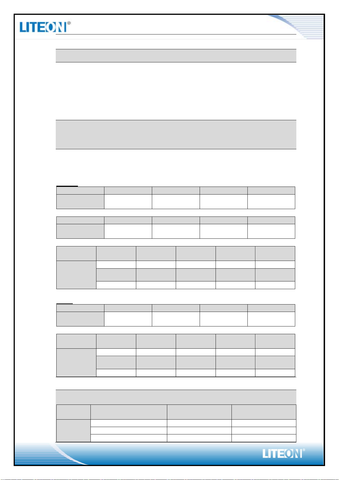
2.4GHz
8: Japan
802.11bg
5.15 ~ 5.85 GHz
802.11b
1Mbps
2Mbps
5.5Mbps
11Mbps
Tgtpwr
(dBm)
17
17
17
17
802.11g
6~24Mbps
36Mbps
48Mbps
54Mbps
Tgtpwr
(dBm)
17
17
17
17
802.11n
HT20
MCS0
MCS1
MCS2
MCS3
MCS4
Tgtpwr
17
17
17
17
17
MCS5
MCS6
MCS7
17
17
17
802.11a
6~24Mbps
36Mbps
48Mbps
54Mbps
Tgtpwr
(dBm)
13
13
12
11
802.11n
HT20
MCS0
MCS1
MCS2
MCS3
MCS4
Tgtpwr
13
13
13
13
12
MCS5
MCS6
MCS7
11
10 9
Receiver Sensitivity
Frequency
Band
Rate
Condition
1x1(1SS)
(dBm)
11b-1M
PER < 8%
-94
11b-11M
PER < 8%
-87
11g-6M
PER < 10%
-91
Network Architecture
Infrastructure mode
11: (Ch. 1-11) – United States
13: (Ch. 1-13) – Europe
Operation Channel
14: (Ch. 1-14) – Japan
5GHz
21: USA
19: EU
Frequency Range
2.400 ~ 2.4835 GHz
802.11a
Transmit Output Power - single chain @ant;
Tolerance:
±2dBm@2.4GHz; ±2.5dBm@5GHz
2.4GHz
(dBm)
5GHz
(dBm)
2.4G
Page 4/13
Page 5

11g-54M
PER < 10%
-75
11n-HT20MCS0
PER < 10%
-92
11n-HT20MCS7
PER < 10%
-71
11a-6M
PER < 10%
-89
11a-54M
PER < 10%
-72
11n-HT20MCS0
PER < 10%
-89
11n-HT20MCS7
PER < 10%
-69
Mode
Average
Peak
2.4G
5G
2.4G
5G
TX
TBDmA
TBDmA
TBDmA
TBDmA
RX
TBDmA
TBDmA
Disable
TBDmA
Sleep
mode
TBDmA
SWREG_IN_WL
VDD33_WL
VDD33_ANT_WL
VDD33_USB_WL
VDD12_BB_PLL_WL
VDD12_SYNTH_WL
5G
Security
WPA, WPA2, WEP 64bit & 128bit, IEEE 802.1X, IEEE 802.11i
Common Function
Operating Voltage
Power Consumption
Antenna Type
3.3 V ±5% I/O supply voltage
Printed Antenna for WiFi/BT/15.4
RECOMMENDED OPERATION CONDITIONS
Symbol Parameter Min Typ Max Units
WL Internal SWREG supply 3.14 3.3 3.46 V
VDD33_RF_WL
VDD33_XTAL_WL
VDD33_PLL_WL
WL Analog High V oltage supply 3.14 3.3 3.46 V
VDD33_SYNTH_WL
DVDD12_WL WL Core Digital supply 1.2 1.26 1.32 V
VDD12_RF_WL
WL Core Analog supply 1.2 1.26 1.32 V
VIH High Level Input voltage 2.4 - 3.6 V
VIL Low Level Input voltage -0.3 - 0.3 V
VOH High Level Output voltage 3.0 - 3.3 V
VOL Low Level Output voltage -0.3 - 0.4 V
Page 5/13
Page 6

MECHANICAL
Page 6/13
Page 7

33
GND
G
Ground
YES
35
32K_XTALI
Optional external 32KHz crystal
YES
37
CHIP_PWD_L_BE
BLE/15.4 Reset Pin
NC
39-41
VDD11_SWREG_OUT
Not used, NC
NC
43-44
VDDIO18_BE
Not used, NC
NC
46
GPIO28_BE
I2S_BCLK
YES
48
GPIO30_BE
I2S_TXD
YES
50
GPIO31_BE
I2S_FSYNC
YES
SPI0_CS1_N / I2C1_Master_SDA /
HS_UART0_DM_RXD
SPI0_CS2_N / I2C1_Master_SCL /
HS_UART0_DM_RFR / BT Active
General-purpose input/output
34
36
38
42
45
47
49
51
52
53
YES
32K_XTALO Optional external 32KHz crystal NC
GND G Ground YES
GND G Ground YES
GND G Ground YES
GPIO29_BE I2S_RXD YES
GPIO32_BE I2S_MCLK YES
GPIO17_BE
YES
GPIO14_BE HS_UART0_DM_CTS YES
GPIO16_BE
YES
54
55
56
57
58
59
60
61
62
63
64
65-66
67-69
70
71
72-75
76
77
78
79
80
81
82
83
GPIO13_BE PWM Out_7 YES
GPIO15_BE HS_UART0_DM_TXD YES
GPIO11_BE I2C0_Master_SDA / JTAG1_BE_TDI YES
GPIO48_BE Ext_32K_IN YES
GPIO9_BE M0&M4_UART0_T X / JTAG1_BE_TDO YES
GPIO10_BE I2C0_Master_SDA / JTAG1_BE_TMS YES
GPIO53_BE JTAG3_BE_TDI YES
GPIO8_BE M0&M4_UART0_RX / JTAG1_BE_TCK YES
GPIO52_BE JTAG3_BE_TMS YES
GPIO51_BE JTAG3_BE_TDO YES
GPIO49_BE I/O
YES
NC Not Connected NC
GND G Ground
NC Not Connected NC
GND G Ground
NC Not Connected NC
GND G Ground
NC Not Connected NC
GPIO50_BE JTAG3_BE_TCK YES
GPIO7_BE BT PRIORITY YES
GPIO41_BE PWR_STATUS YES
GPIO6_BE WLAN ACTIVE YES
GPIO60_BE HS UART2_DM_TXD(O) / BT PRIORITY YES
GPIO5_BE BT ACTIVE YES
Page 7/13
Page 8

ENVIRONMENTAL
OPERATING
Operating Temperature : -20 to 80 °C
Relative Humidity: 5-90% (non-condensing)
TORAGE
S
Temperature: -40 to 80 °C (-40 to 176 °F)
Relative Humidity: 5-95% (non-condensing)
Page 8/13
Page 9

WARNINGS
FCC Statement:
Federal Communication Commission Interference Statement
This equipment has been tested and found to comply with the limits for a Class B digital
device, pursuant to Part 15 of the FCC Rules. These limits are designed to provide reasonable
protection against harmful interference in a residential installation. This equipment generates,
uses and can radiate radio frequency energy and, if not installed and used in accordance with
the instructions, may cause harmful interference to radio communications. However, there is
no guarantee that interference will not occur in a particular installation. If this equipment does
cause harmful interference to radio or television reception, which can be determined by
turning the equipment off and on, the user is encouraged to try to correct the interference by
one of the following measures:
● Reorient or relocate the receiving antenna.
● Increase the separation between the equipment and receiver.
● Connect the equipment into an outlet on a circuit different from that to which the
receiver is connected.
● Consult the dealer or an experienced radio/TV technician for help.
FCC Caution: Any changes or modifications not expressly approved by the party responsible
for
compliance could void the user’s authority to operate this equipment.
This device complies with Part 15 of the FCC Rules. Operation is subject to the following two
conditions: (1) This device may not cause harmful interference, and (2) this device must
accept any interference received, including interference that may cause undesired operation.
For product available in the USA/Canada market, only channel 1~11 can be operated.
Selection of other channels is not possible.
This device and its antenna(s) must not be co-located with any other transmitters except in
accordance with FCC multi-transmitter product procedures.
Refering to the multi-transmitter policy, multiple-transmitter(s) and module(s) can be
operated simultaneously without C2P.
This device is restricted for indoor use.
Page 9/13
Page 10

IMPORTANT NOTE:
FCC Radiation Exposure Statement:
This equipment complies with FCC radiation exposure limits set forth for an uncontrolled
environment. This equipment should be installed and operated with minimum distance 20 cm
between the radiator & your body.
IMPORTANT NOTE:
This module is intended for OEM integrator. The OEM integrator is responsible for the
compliance to all the rules that apply to the product into which this certified RF module is
integrated.
Additional testing and certification may be necessary when multiple modules are used.
20 cm minimum distance has to be able to be maintained between the antenna and the users
for the host this module is integrated into. Under such configuration, the FCC radiation
exposure limits set forth for an population/uncontrolled environment can be satisfied.
Any changes or modifications not expressly approved by the manufacturer could void the
user's authority to operate this equipment.
USERS MANUAL OF THE END PRODUCT:
In the users manual of the end product, the end user has to be informed to keep at least 20 cm
separation with the antenna while this end product is installed and operated. The end user has
to be informed that the FCC radio-frequency exposure guidelines for an uncontrolled
environment can be satisfied. The end user has to also be informed that any changes or
modifications not expressly approved by the manufacturer could void the user's authority to
operate this equipment. If the size of the end product is smaller than 8x10cm, then additional
FCC part 15.19 statement is required to be available in the users manual: This device
complies with Part 15 of FCC rules. Operation is subject to the following two conditions: (1)
this device may not cause harmful interference and (2) this device must accept any
interference received, including interference that may cause undesired operation.
LABEL OF THE END PRODUCT:
The final end product must be labeled in a visible area with the following " Contains TX FCC
ID: PPQ-WCBN3516A ". If the size of the end product is larger than 8x10cm, then the
following FCC part 15.19 statement has to also be available on the label: This device
complies with Part 15 of FCC rules. Operation is subject to the following two conditions: (1)
this device may not cause harmful interference and (2) this device m ust acc ept any
interference received, including interference that may cause undesired operation.
Page 10/13
Page 11

IC Statement:
This device complies with Industry Canada license-exempt RSS standard(s). Operation is
subject to the following two conditions: (1) this device may not cause interference, and (2)
this device must accept any interference, including interference that may cause undesired
operation of the device.
Le présent appareil est conforme aux CNR d'Industrie Canada applicables aux appareils radio
exempts de licence. L'exploitation est autorisée aux deux conditions suivantes : (1) l'appareil
ne doit pas produire de brouillage, et (2) l'utilisateur de l'appareil doit accepter tout brouillage
radioélectrique subi, même si le brouillage est susceptible d'en compromettre le
fonctionnement.
For product available in the USA/Canada market, only channel 1~11 can be operated.
Selection of other channels is not possible.
Pour les produits disponibles aux États-Unis / Canada du marché, seul le canal 1 à 11 peuvent
être exploités. Sélection d'autres canaux n'est pas possible.
This device and its antenna(s) must not be co-located with any other transmitters except in
accordance with IC multi-transmitter product procedures.
Refering to the multi-transmitter policy, multiple-transmitter(s) and module(s) can be
operated simultaneously without reassessment permissive change.
Cet appareil et son antenne (s) ne doit pas être co-localisés ou fonctionnement en association
avec une autre antenne ou transmetteur.
The device for operation in the band 5150–5250 MHz is only for indoor use to reduce the
potential for harmful interference to co-channel mobile satellite systems.
les dispositifs fonctionnant dans la bande 5150-5250 MHz sont réservés uniquement pour une
utilisation à l’intérieur afin de réduire les risques de brouillage préjudiciable aux systèmes de
satellites mobiles utilisant les mêmes canaux.
The maximum antenna gain permitted for devices in the band 5725-5850 MHz shall be such
that the equipment still complies with the e.i.r.p. limits specified for point-to-point and
non-point-to-point operation as appropriate.
le gain maximal d’antenne permis (pour les dispositifs utilisant la bande 5725-5850 MHz)
doit se conformer à la limite de p.i.r.e. spécifiée pour l’exploitation point à point et non point
à point, selon le cas.
Dynamic Frequency Selection (DFS) for devices operating in the bands 5250- 5350 MHz,
5470-5600 MHz and 5650-5725 MHz.
Page 11/13
Page 12

Sélection dynamique de fréquences (DFS) pour les dispositifs fonctionnant dans les bandes
5250-5350 MHz, 5470-5600 MHz et 5650-5725 MHz.
The maximum antenna gain permitted for devices in the bands 5250-5350 MHz and
5470-5725 MHz shall be such that the equipment still complies with the e.i.r.p. limit.
le gain maximal d’antenne permis pour les dispositifs utilisant les bandes 5250-5350 MHz et
5470-5725 MHz doit se conformer à la limite de p.i.r.e.
Users should also be advised that high-power radars are allocated as primary users (i.e.
priority users) of the bands 5250-5350 MHz and 5650-5850 MHz and that these radars
could cause interference and/or damage to LE-LAN devices.
De plus, les utilisateurs devraient aussi être avisés que les utilisateurs de radars de haute
puissance sont désignés utilisateurs principaux (c.-à-d., qu’ils ont la priorité) pour les bandes
5250-5350 MHz et 5650-5850 MHz et que ces radars pourraient causer du brouillage et/ou
des dommages aux dispositifs LAN-EL.
For indoor use only.
Pour une utilisation en intérieur uniquement.
IMPORTANT NOTE:
IC Radiation Exposure Statement:
This equipment complies with IC RSS-102 radiation exposure limits set forth for an
uncontrolled environment. This equipment should be installed and operated with minimum
distance 20 cm between the radiator & your body.
Cet équipement est conforme aux limites d'exposition aux rayonnements IC établies pour un
environnement non contrôlé. Cet équipement doit être installé et utilisé avec un minimum de
20 cm de distance entre la source de rayonnement et votre corps.
This radio transmitter (IC: 4491A-WCBN3516A) has been approved by Industry Canada to
operate with the antenna types listed below with the maximum permissible gain and required
antenna impedance for each antenna type indicated. Antenna types not included in this list,
having a gain greater than the maximum gain indicated for that type, are strictly prohibited for
use with this device.
Le présent émetteur radio (IC: 4491A-WCBN3516A) a été approuvé par Industrie Canada
pour fonctionner avec les types d'antenne énumérés ci-dessous et ayant un gain admissible
maximal et l'impédance requise pour chaque type d'antenne. Les types d'antenne non inclus
dans cette liste, ou dont le gain est supérieur au gain maximal indiqué, sont strictement
interdits pour l'exploitation de l'émetteur.
Page 12/13
Page 13

This module is intended for OEM integrator. The OEM integrator is still responsible for the
IC compliance requirement of the end product, which integrates this module.
Any changes or modifications not expressly approved by the manufacturer could void the
user's authority to operate this equipment.
USERS MANUAL OF THE END PRODUCT:
In the users manual of the end product, the end user has to be informed to keep at least 20 cm
separation with the antenna while this end product is installed and operated. The end user has
to be informed that the IC radio-frequency exposure guidelines for an uncontrolled
environment can be satisfied. The end user has to also be informed that any changes or
modifications not expressly approved by the manufacturer could void the user's authority to
operate this equipment. Operation is subject to the following two conditions: (1) this device
may not cause harmful interference and (2) this device must accept any interference received,
including interference that may cause undesired operation.
LABEL OF THE END PRODUCT:
The final end product must be labeled in a visible area with the following " Contains TX IC :
4491A-WCBN3516A".
Japan Statement:
5GHz product for indoor use only.
CE Statement:
This equipment complies with EU radiation exposure limits set forth for an uncontrol led
environment. This equipment should be installed and operated with minimum distance 20 cm
between the radiator & your body.
Page 13/13
 Loading...