

Page 1
3rd Generation of
Basic/Smart/Smart Plus/Intelligent
Charger-32A
User Manual
Revision 1.11
Page 2

User Manual Rev 1.11
Basic/Smart/Smart Plus/Intelligent Charger-32A
1
Page 3
User Manual Rev 1.11
Basic/Smart/Smart Plus/Intelligent Charger-32A
2
IMPORTANT SAFETY INSTRUCTIONS
This document contains instructions and warnings that must be followed when installing and using the
Electric Vehicle Supply Equipment (EVSE). Before installing or using the EVSE, read this entire document
as well as WARNING and CAUTION markings in this document.
Safety Instructions
The symbols used have the following meaning:
• The charge point must be installed only by licensed electricians.
• Make sure that the materials used and the installation procedures follow local building codes and
safety standards.
• The information provided in this manual in no way exempts the user of responsibility to follow all
applicable codes or safety standards.
• This document provides instructions for the charge point and should not be used for any other
product. Before installation or use of this product, review this manual carefully and consult with
a licensed contractor, licensed electrician, or trained installation expert to make sure of
compliance with local building codes and safety standards.
WARNING: RISK OF PERSONAL INJURY
WARNING: RISK OF ELECTRIC SHOCK
WARNING: RISK OF FIRE
CAUTION: RISK OF DAMAGE TO THE EQUIPMENT
Page 4

User Manual Rev 1.11
Basic/Smart/Smart Plus/Intelligent Charger-32A
3
Repair and Maintenance Clause
• Only licensed electricians can repair or maintain the charge point. It is forbidden for general users
to repair or maintain it.
• Turn off input power before repair or maintenance the charge point.
Federal Communication Commission Interference Statement
This device complies with Part 15 of the FCC Rules. Operation is subject to the following two conditions:
(1) This device may not cause harmful interference, and (2) this device must accept any interference
received, including interference that may cause undesired operation.
This equipment has been tested and found to comply with the limits for a Class B digital device,
pursuant to Part 15 of the FCC Rules. These limits are designed to provide reasonable protection
against harmful interference in a residential installation. This equipment generates, uses and can
radiate radio frequency energy and, if not installed and used in accordance with the instructions, may
cause harmful interference to radio communications. However, there is no guarantee that
interference will not occur in a particular installation. If this equipment does cause harmful
interference to radio or television reception, which can be determined by turning the equipment off
and on, the user is encouraged to try to correct the interference by one of the following measures:
- Reorient or relocate the receiving antenna.
- Increase the separation between the equipment and receiver.
- Connect the equipment into an outlet on a circuit different from that
to which the receiver is connected.
- Consult the dealer or an experienced radio/TV technician for help.
FCC Caution: Any changes or modifications not expressly approved by the party responsible for
compliance could void the user's authority to operate this equipment.
This transmitter must not be co-located or operating in conjunction with any other antenna or
transmitter.
Radiation Exposure Statement:
This equipment complies with FCC radiation exposure limits set forth for an uncontrolled environment.
This equipment should be installed and operated with greater than 20cm between the radiator & your
body.
Page 5

User Manual Rev 1.11
Basic/Smart/Smart Plus/Intelligent Charger-32A
4
Industry Canada statement:
This device complies with ISED’s license-exempt RSSs. Operation is subject to the following two
conditions: (1) This device may not cause harmful interference, and (2) this device must accept any
interference received, including interference that may cause undesired operation.
Le présent appareil est conforme aux CNR d’ ISED applicables aux appareils radio exempts de licence.
L’exploitation est autorisée aux deux conditions suivantes : (1) le dispositif ne doit pas produire de
brouillage préjudiciable, et (2) ce dispositif doit accepter tout brouillage reçu, y compris un brouillage
susceptible de provoquer un fonctionnement indésirable.
Radiation Exposure Statement:
This equipment complies with ISED radiation exposure limits set forth for an uncontrolled environment.
This equipment should be installed and operated with greater than 20cm between the radiator & your
body.
Déclaration d'exposition aux radiations:
Cet équipement est conforme aux limites d'exposition aux rayonnements ISED établies pour un
environnement non contrôlé. Cet équipement doit être installé et utilisé à plus de 20 cm entre le
radiateur et votre corps.
WARNING: RISK OF ELECTRIC SHOCK
Basic precautions should always be followed when using electrical products, including the
following:
• Read all the instructions before using this product.
• This device should be supervised when used around children.
• Do not put fingers into the EV connector.
• Do not uses this product if the flexible power cord or EV cable is frayed, has broken
insulation, or any other signs of damage.
• Do not use this product if the enclosure or the EV connector is broken, cracked, open, or
shows any other indication of damage.
WARNING: RISK OF ELECTRIC SHOCK
Improper connection of the equipment grounding conductor can result in a risk of electric
shock. Check with a qualified electrician or serviceman if you are in doubt as to whether the
product is properly ground-ed.
Page 6

User Manual Rev 1.11
Basic/Smart/Smart Plus/Intelligent Charger-32A
5
SAVE THESE INSTRUCTIONS
WARNING: RISK OF ELECTRIC SHOCK
• Do not touch live electrical parts.
• Incorrect connections may cause electric shock.
WARNING: This equipment is intended only for charging vehicles that do not require ventilation
during charging. Please refer to your vehicle’s owner’s manual to determine ventilation
requirements.
WARNING: Do not use extender cables to increase the length of the charging cable. Maximum
length is limited to 25 feet by the National Fire Protection Agency.
WARNING: Do not drag the charge point by input power cord.
Page 7

User Manual Rev 1.11
Basic/Smart/Smart Plus/Intelligent Charger-32A
6
Contents
1 Introduction .......................................................................................................................................... 9
Product view ............................................................................................................................... 9
2 Specifications ...................................................................................................................................... 15
Product specifications ............................................................................................................... 15
3 Installation .......................................................................................................................................... 17
Before installation ..................................................................................................................... 17
3.1.1 Safety check ................................................................................................................. 17
3.1.2 Grounding instructions ................................................................................................ 17
Tools & parts required for installation ...................................................................................... 18
Install the SIM card (for IC3 only) ............................................................................................. 18
Install the charge point ............................................................................................................. 23
Input cord connection (for SC3+/IC3 only) ............................................................................... 26
Install the holster ...................................................................................................................... 29
Getting started (for SC3/SC3+/IC3 only) ................................................................................... 32
3.7.1 Setting up the local network ........................................................................................ 32
3.7.2 Log in ............................................................................................................................ 34
Web-page overview (for SC3/SC3+/IC3 only) ........................................................................... 35
3.8.1 Menu overview ............................................................................................................ 35
3.8.2 Configuration menu ..................................................................................................... 36
3.8.3 Maintenance menu ...................................................................................................... 37
3.8.4 EVSE Status ................................................................................................................... 38
3.8.5 LLM Status menu [support only on SC3+/IC3] ............................................................. 39
3.8.6 Security menu .............................................................................................................. 40
Configuration ............................................................................................................................ 41
Page 8

User Manual Rev 1.11
Basic/Smart/Smart Plus/Intelligent Charger-32A
7
3.9.1 Factory settings ............................................................................................................ 41
3.9.2 Station settings............................................................................................................. 42
3.9.3 OCPP settings ............................................................................................................... 44
3.9.4 Communication settings .............................................................................................. 51
Maintenance ............................................................................................................................. 59
3.10.1 Reboot .......................................................................................................................... 59
3.10.2 Firmware upgrade ........................................................................................................ 62
EVSE Status ............................................................................................................................... 63
LLM Status (SC3+/IC3 support only) ......................................................................................... 64
3.12.1 LLM information ........................................................................................................... 64
3.12.2 Gateway/Client group table ......................................................................................... 65
Security ..................................................................................................................................... 66
3.13.1 Change password ......................................................................................................... 66
4 Operations .......................................................................................................................................... 67
Charging status indicators ......................................................................................................... 67
Authorization (for SC3+/IC3 only) ............................................................................................. 68
4.2.1 Online Authorization .................................................................................................... 68
4.2.2 Local Authorization ...................................................................................................... 68
Charging an Electric Vehicle (EV) .............................................................................................. 69
4.3.1 Plug and Charge ........................................................................................................... 69
4.3.2 RFID card (for SC3+/IC3 only) ....................................................................................... 70
Stop charging ............................................................................................................................ 70
4.4.1 Interrupt charging ........................................................................................................ 70
4.4.2 Auto restart .................................................................................................................. 70
4.4.3 Power outage recovery ................................................................................................ 70
General care .............................................................................................................................. 71
Page 9

User Manual Rev 1.11
Basic/Smart/Smart Plus/Intelligent Charger-32A
8
Customer support ..................................................................................................................... 71
Page 10
User Manual Rev 1.11
Basic/Smart/Smart Plus/Intelligent Charger-32A
9
1 Introduction
This user manual applies to “32A Level 2 AC Charger for Plug-in Electric Vehicles (PEVs) and Battery Electric
Vehicles (BEVs)”.
The Level 2 Electric Vehicle Supply Equipment (EVSE) with 32A capabilities will be used in North America.
It can provide a shorter charging time than the traditional 16A EVSE.
!!! Any unauthorized modifications will void the manufacturer’s warranty. !!!
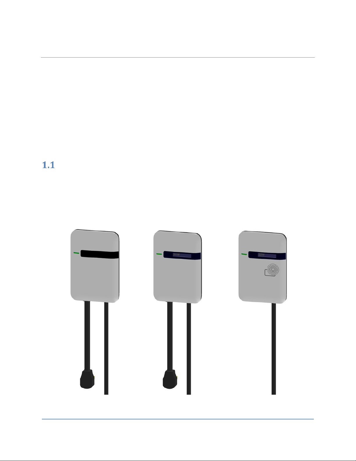
Product view
Different models of 3rd Generation of Charger:
Basic Charger-32A (BC3) Smart Charger-32A (SC3) Intelligent Charger-32A (IC3)
Smart Charger Plus-32A (SC3+)
Figure 1-1 Front view
Page 11
User Manual Rev 1.11
Basic/Smart/Smart Plus/Intelligent Charger-32A
10
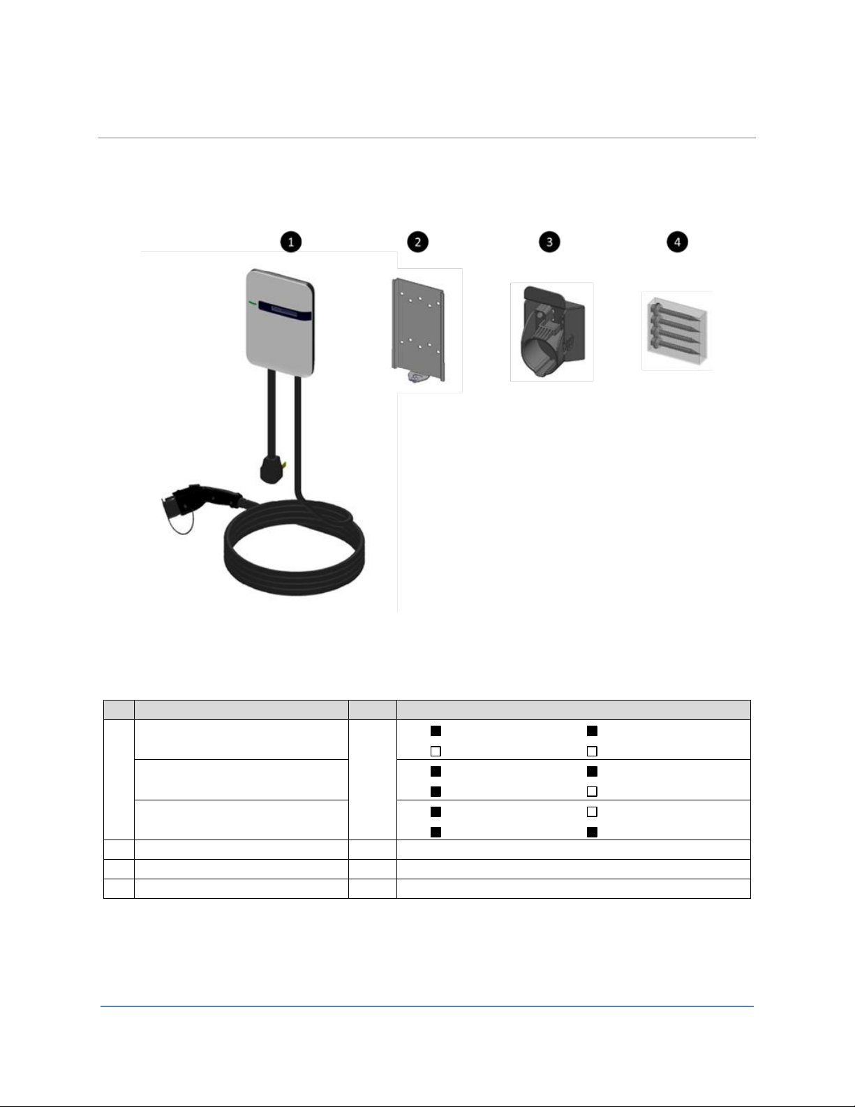
Box Contents
See the table for content differences of three models.
Figure 1-2 Box contents
Table 1-1 Accessories in the box
Description
QTY
Remark
1
Basic Charger-32A (BC3)
1
Charging Plug
Input Power Cord
OLED Display
RFID Icon
Smart Charger-32A (SC3)
Smart Charger Plus-32A (SC3+)
Charging Plug
Input Power Cord
OLED Display
RFID Icon
Intelligent Charger-32A (IC3)
Charging Plug
Input Power Cord
OLED Display
RFID Icon
2
Mounting Bracket
1
Attached to the back of the charge point
3
Holster ASSY
1
With Hook x1, Holster x1 & M4xL15 tapping screw x2
4
Screw Bag
1
With #12xL50 tapping screw x4
Page 12
User Manual Rev 1.11
Basic/Smart/Smart Plus/Intelligent Charger-32A
11
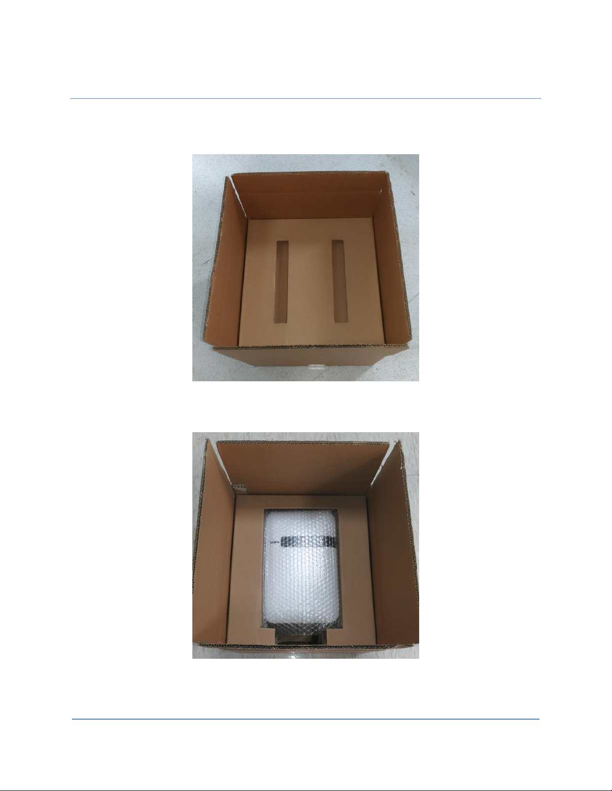
Box Opening Process (Take Intelligent Charger-32A as example.)
1. Open the carton and remove the upper partition.
Figure 1-3 Opening the carton
Figure 1-4 Charge point device
Page 13
User Manual Rev 1.11
Basic/Smart/Smart Plus/Intelligent Charger-32A
12
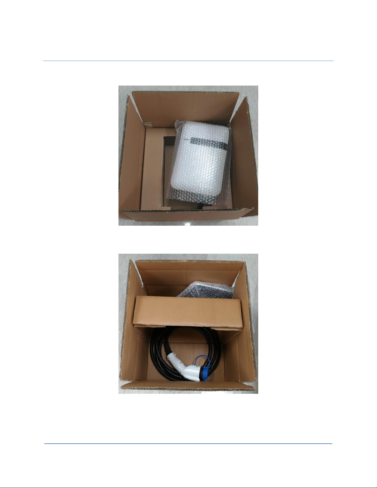
2. Take out the charge point and upturn middle partition. The charging plug is in the bottom of the carton.
Figure 1-5 Take out the charge point
Figure 1-6 Charging plug
Page 14
User Manual Rev 1.11
Basic/Smart/Smart Plus/Intelligent Charger-32A
13
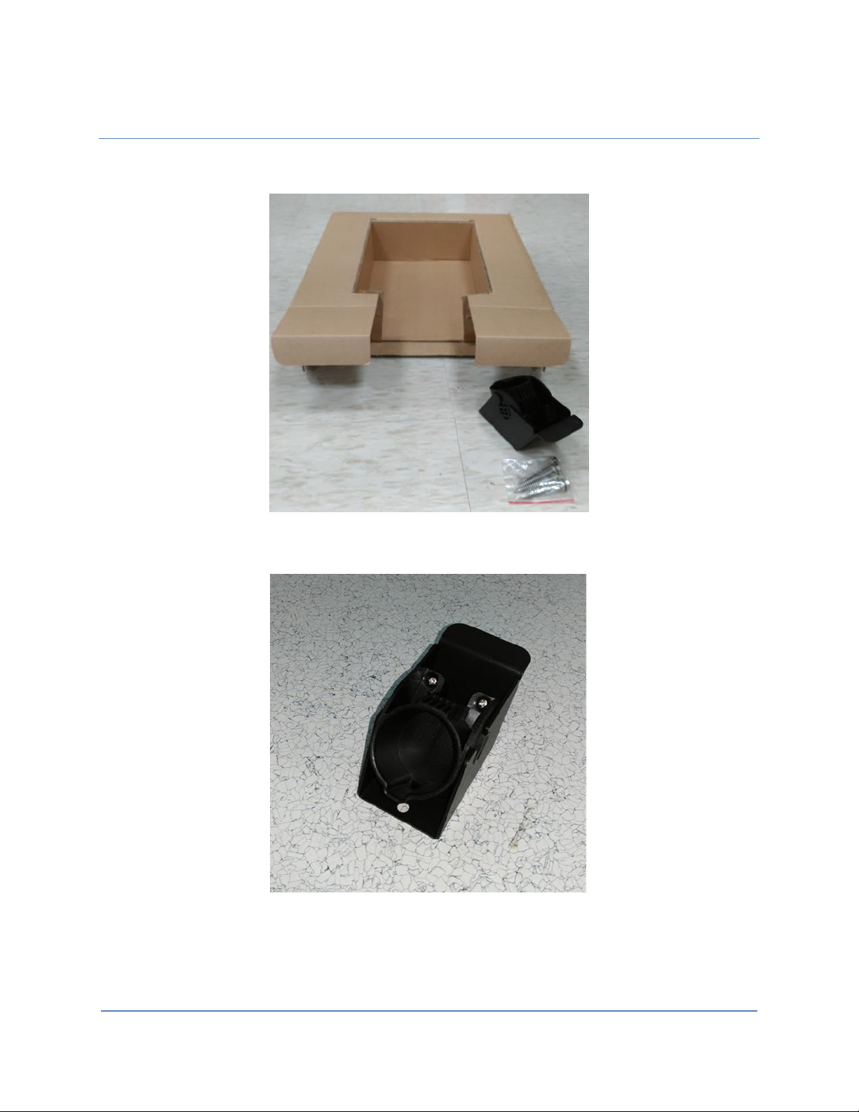
3. The hook and holster is placed inside the right of the middle partition.
Figure 1-7 Accessories inside the middle partition
Figure 1-8 Hook and holster
Page 15
User Manual Rev 1.11
Basic/Smart/Smart Plus/Intelligent Charger-32A
14
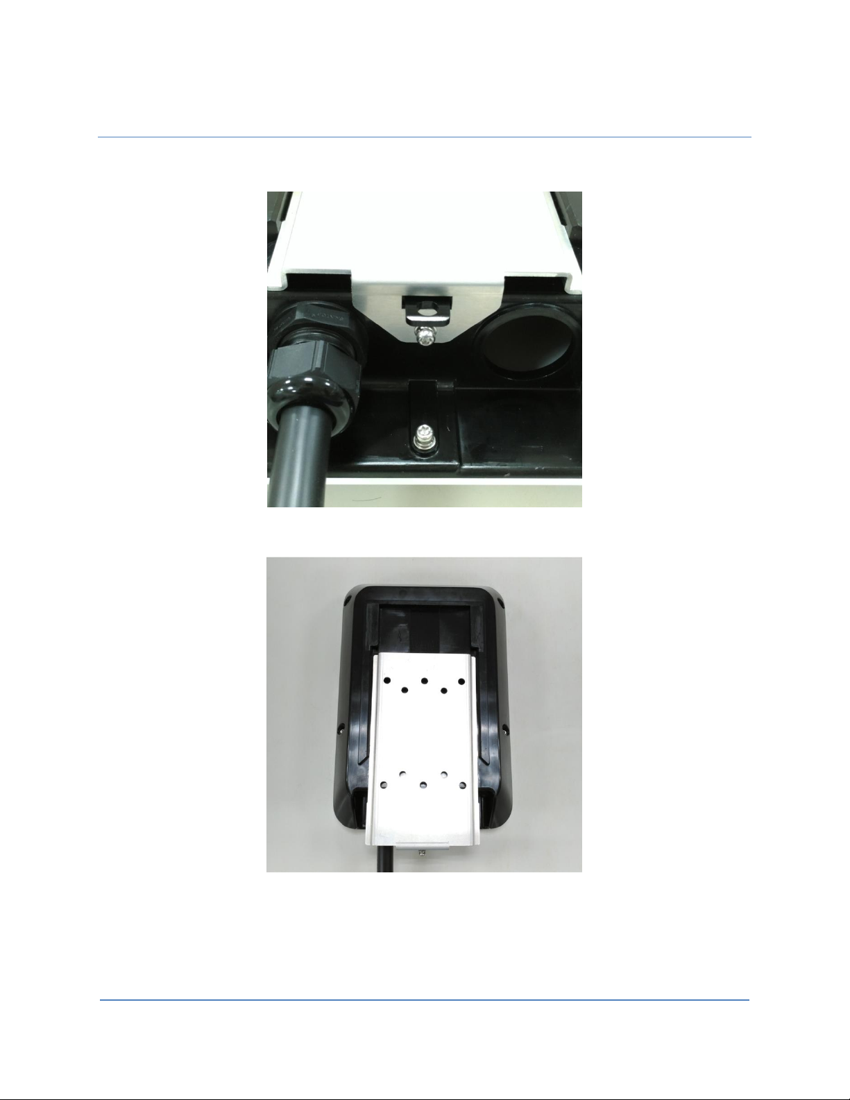
4. Release the bottom screw, then the wall mounting bracket can be removed.
Figure 1-9 Release the screw
Figure 1-10 Remove the mounting bracket
Page 16

User Manual Rev 1.11
Basic/Smart/Smart Plus/Intelligent Charger-32A
15
2 Specifications
Product specifications
(Note: Certification in process)
Table 2-1 Product specifications
Item
BC3
SC3
SC3+
IC3
Application
Residential
Commercial
Voltage (Vac)
208/240VAC, Single Phase
Frequency (Hz)
60 Hz
Current (Rms)
32 A
Charging Connector
SAE J1772 Type 1
Charging Cable Length
25 ft. (18 ft. optional)
Metering Accuracy
N/A
Embedded ± 3%
Real Time Clock
N/A
Yes (7 days)
Indications
• Green Steady: Ready
• Green Flashing (Fast): Authorized, wait for EV Connect
• Green Flashing (Slow): Suspend (Occupying)
• Blue Flashing (Slow): Charging
• Red Steady: Unrecoverable Fault
• Red Flashing (Slow): Recoverable Fault
• Yellow Steady: Out of Service
• Yellow Flashing (Slow): Booting / Firmware Upgrading
Remark
• Fast Flash: On Time 300ms, Off Time 200ms, 2Hz
• Slow Flash: On Time 1200ms, Off Time 800ms, 0.5Hz
Wi-Fi
N/A
802.11 b/g/n
Cellular
N/A
LTE Cat. 1
(AT&T or Verizon)
RFID
N/A
ISO 14443 A/B,
ISO 15693,
NFC,
NEMA interoperability protocol
Display
N/A
116(L)*8.5(W)*37(H)mm, 5.57mm CHARAXTER HEIGHT, 5*8
DOT MATRIX, OLED 20x2
Data Protocol
N/A
OCPP 1.6
Operation Temp.
-30 ~ 50 ℃ / -22 ~ 122 ℉
Storage Temp.
-40 ~ 70℃ / -40 ~ 158 ℉
Mounting Type
Wall mount / Pole mount (optional)
Wiring Type
NEMA 6-50
Hard-wired
IP Performance
NEMA 4
Impact Resistance
IK10
Dimension (H x W x D, inch)
11.14” x 7.56” x 3.11”
Page 17

User Manual Rev 1.11
Basic/Smart/Smart Plus/Intelligent Charger-32A
16
Item
BC3
SC3
SC3+
IC3
Web Portal Management
N/A
Yes
Console Management
Yes
Certification
UL 50/991/1449/1998/2231/2594
FCC Part 15B
N/A
FCC Part 15.225 (RFID 13.56MHz)
FCC Part 15.247 (WLAN 2.4GHz)
N/A
FCC Part 27
(AT&T) or
FCC Part 27
(Verizon)
Page 18

User Manual Rev 1.11
Basic/Smart/Smart Plus/Intelligent Charger-32A
17
3 Installation
Before installation
3.1.1 Safety check
The charge point must be installed only by a licensed electrician in accordance with the provisions of the
local electrical industry construction and should comply with national electrical codes and standards.
Before installing the charge point, make sure you have read all of these instructions in this manual and
fully understand its contents.
Appropriate protection is required when connecting to a main switchboard. The tools and parts used as
outlined in the section “Tools & parts required for installation”.
3.1.2 Grounding instructions
The charge point must be implemented equipment grounding through a permanent wiring system or an
equipment grounding conductor. Use a wire with a dedicated grounding wire and a ring terminal and
connected to the equipment ground terminal block for grounding.
CAUTION: Disconnect the power supply before installing or repairing the charge point. Failure
to do so may result in physical injury or damage to the power supply system and the charge
point.
Page 19

User Manual Rev 1.11
Basic/Smart/Smart Plus/Intelligent Charger-32A
18
Tools & parts required for installation
Table 3-1 Tools & parts required for installation
Tool
QTY
Model
Size
Supplier
Remark
Mounting Bracket
1
All
194x109x9 mm
Model Accessories
Fasten charge point to the
wall
Holster ASSY
1
All
58x58x70 mm
Model Accessories
Hold EV charging plug
Screw 4 All
Tapping: #12
Model Accessories
Fasten Mounting Bracket &
Hook
Mechanical: M6
Commercially Available
Wire, Copper
3
SC3+
/IC3
8 AWG
Commercially Available
UL1015 (recommended)
Heat Shrink Tube
3
SC3+
/IC3
For 8 AWG wire
Commercially Available
Protect wires & terminals
Terminal
3
SC3+
/IC3
For 8 AWG wire
Commercially Available
Connect input wires to the
terminal block
Conduit
1
SC3+
/IC3
1 inch
Commercially Available
Protect power cable
Torx Screwdriver
1
All
T20
Commercially Available
Philips Screwdriver
1
All
PH3
Commercially Available
Hexagon Socket
1
All
5/16
Commercially Available
Tighten #12 Tapping screws
Torque Wrench
1
All
35 kgf-cm min
Commercially Available
Install the SIM card (for IC3 only)
1. Disassemble top cover
1-1 Loosen the star screws (x5).
Page 20

User Manual Rev 1.11
Basic/Smart/Smart Plus/Intelligent Charger-32A
19
Figure 3-1 Five screws in the Base Cover position
2. Find SIM card socket
Figure 3-2 Position of SIM card socket
Page 21
User Manual Rev 1.11
Basic/Smart/Smart Plus/Intelligent Charger-32A
20
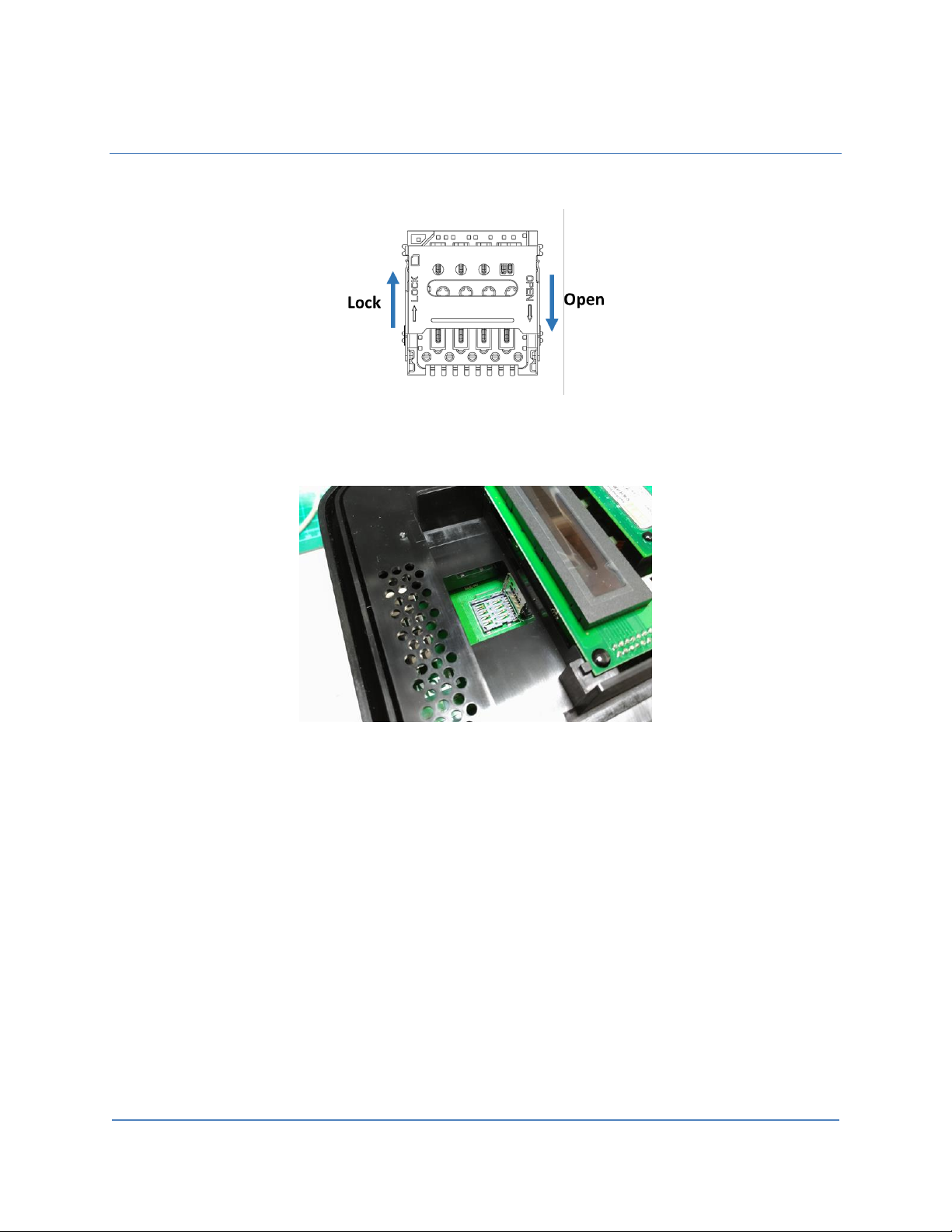
3. Insert SIM card
Figure 3-3 SIM card socket and cover Open/Close direction
3-1. Push down the cover to open SIM card socket.
Figure 3-4 Open SIM card socket
3-2. Prepare the SIM card. (Use micro-SIM, 15mm x 12mm.)
Page 22
User Manual Rev 1.11
Basic/Smart/Smart Plus/Intelligent Charger-32A
21
.
Figure 3-5 Prepare the SIM card
Page 23

User Manual Rev 1.11
Basic/Smart/Smart Plus/Intelligent Charger-32A
22
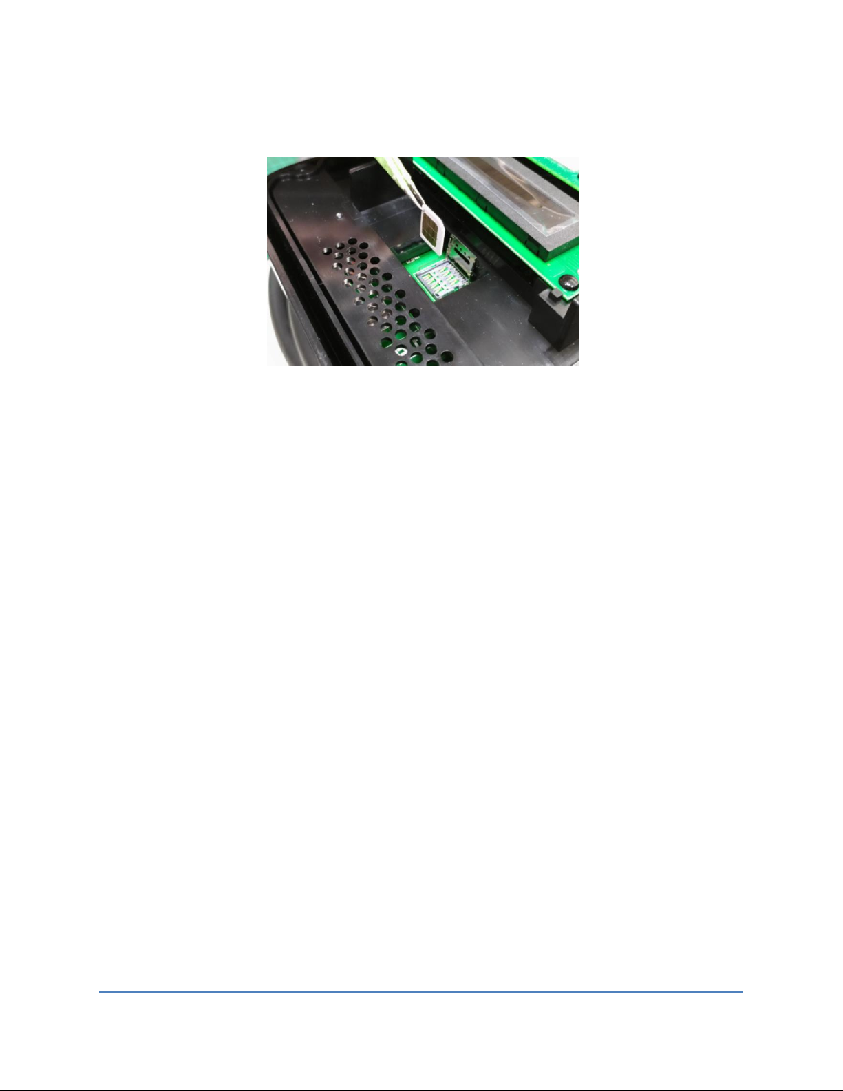
3-3. Insert the SIM card.
Figure 3-6 Insert the SIM card
3-4. Close the SIM card socket and push the cover toward lock direction to lock the cover.
Figure 3-7 Lock SIM card socket cover
3-5. Reassemble the top cover. Please refer to the following torque. SIM card installation is
completed.
Screw
Torque
M4
16 kgf.cm
13.88 lb-in
Page 24

User Manual Rev 1.11
Basic/Smart/Smart Plus/Intelligent Charger-32A
23
Install the charge point
1. Secure the main body mounting bracket to the wall with appropriate screw.
Follow applicable accessibility requirements for the mounting position. The unit shall be stored or
located at a sufficient height. For indoor site, it is not lower than 18” (450 mm) and not higher than
4” (1.2m). For outdoor site, it is not lower than 24” (600 mm) and not higher than 4” (1.2m). Refer
to Article 625, NEC.
The mounting bracket has ten screw holes. If only two screws be used to fasten the mounting
bracket, the screws should pass through the middle two screw holes of the mounting bracket. The
other screw holes are reserved for the user.
Figure 3-8 Fixing mounting bracket Figure 3-9 Screw holes of mounting bracket
Screw suggestion:
a. For masonry walls, use M6 mechanical screws. (Commercially available)
b. For finished walls supported by wood studs, use 1/4”or M6 tapping screws. (Commercially
available)
c. Please use following torque force.
Screw
Torque
M6
25 kgf.cm min
21.7 lb-in min
#12
25 kgf.cm min
21.7 lb-in min
Page 25

User Manual Rev 1.11
Basic/Smart/Smart Plus/Intelligent Charger-32A
24
2. Mount charge point onto mounting bracket and lock the screw.
2-1. Put the charge point on the mounting bracket.
2-2. Fix charge point on mounting bracket by M4 screw and screw washer.
2-3. Please refer to the following torque.
Screw
Torque
M4
16 kgf.cm
13.88 lb-in
Figure 3-10 Charge point and mounting bracket
Figure 3-11 Screw locking position
Page 26

User Manual Rev 1.11
Basic/Smart/Smart Plus/Intelligent Charger-32A
25
3. Plug in the power cord. (BC3/SC3 ONLY)
The outlet should be located at 20-26 inch from the ground. Refer to the installation template to
decide where to install the charge point.
Figure 3-12 Plug in the power cord
Page 27

User Manual Rev 1.11
Basic/Smart/Smart Plus/Intelligent Charger-32A
26
Input cord connection (for SC3+/IC3 only)
1. Choose the appropriate conduit in accordance with all applicable state, local and
national electrical codes and standards.
Figure 3-13 Conduit. Figure 3-14 Right angle conduit
2. Clamp copper terminal to connect copper wire. The clamp point is covered by heat shrink
tube for protecting.
2-1 Refer to the following wire specification. Use conductor type other than RHH, RHW and RHW-2
with outer covering.
Model
Terminal
Conductor
Rating
Smart Charger Plus-32A
Intelligent Charger-32A
L1, L2,G
8 AWG
90C copper wire
Figure 3-15 Copper terminal, heat shrink tube and copper wire.
Page 28

User Manual Rev 1.11
Basic/Smart/Smart Plus/Intelligent Charger-32A
27
3. Electrical wiring to the charge point.
3-1. Disassemble top cover.
3-2. Use Philips screwdriver to release terminal screws.
3-3. Fold the wire end to pass through the conduit and insert them into the input hole.
3-4. Fix the copper wire on the corresponding terminal block. The wiring instruction is printed in front
of the terminal block (L1/L2/G).
3-5. Use the following torque to connect the wire terminal to the terminal block.
Screw
Torque
M4
16 kgf.cm
13.88 lb-in
Figure 3-16 Input wiring
CAUTION: To reduce the risk of fire, connect only to a circuit provided with 40 amperes
maximum branch circuit overcurrent protection in accordance with the National Electrical
Code, ANSI/NFPA 70, and the Canadian Electrical Code, Part I, C22.1.
Page 29

User Manual Rev 1.11
Basic/Smart/Smart Plus/Intelligent Charger-32A
28
Model
Current Rating
Smart Charger Plus-32A
Intelligent Charger-32A
32 A
3-6. Lock the conduit on the enclosure. Please refer to the following torque.
Conduit
Torque
1 “
35 kgf.cm
30.36 lb-in
3-7. Reassemble top cover. Please refer to the following torque.
Screw
Torque
M4
16 kgf.cm
13.88 lb-in
Page 30

User Manual Rev 1.11
Basic/Smart/Smart Plus/Intelligent Charger-32A
29
Install the holster
1. Separate the holster from hook.
Figure 3-17 Separate the holster
2. Fasten the hook on the wall with appropriate screws.
2-1. For finished walls supported by wood studs, use #12 tapping screws (x2).
2-2. The recommend torque is 25 kgf.cm (21.7 lb-in).
Figure 3-18 Secure the hook
Page 31

User Manual Rev 1.11
Basic/Smart/Smart Plus/Intelligent Charger-32A
30
3. Make the holster face up and combine with the hook.
Figure 3-19 Secure the holster
4. Rotate the holster down totally.
Figure 3-20 Rotate the holster
Page 32

User Manual Rev 1.11
Basic/Smart/Smart Plus/Intelligent Charger-32A
31
5. Keep the holster in this state and tighten screws completely.
Figure 3-21 Lock screws
6. Place EV charging plug on the holster.
Figure 3-22 Place EV charging plug.
Page 33

User Manual Rev 1.11
Basic/Smart/Smart Plus/Intelligent Charger-32A
32
Getting started (for SC3/SC3+/IC3 only)
3.7.1 Setting up the local network
Firstly, connect a computer to the charge point using an Ethernet cable.
Figure 3-23 Location of Ethernet RJ-45 port
Page 34

User Manual Rev 1.11
Basic/Smart/Smart Plus/Intelligent Charger-32A
33
Secondly, set up a dynamic IP Address on your computer. For windows system, choose “Obtain an IP
address automatically” in Internet Protocol Version 4 (TCP/IPv4) Properties dialog like the following
figure.
Page 35

User Manual Rev 1.11
Basic/Smart/Smart Plus/Intelligent Charger-32A
34
3.7.2 Log in
Open a web browser (Internet Explorer for example) and enter the IP address of SC3/SC3+/IC3. Please
enter the text below in the address field of the browser and press enter.
http://192.168.199.1 If “Netwrok Mode” is Gateway and “Group Use External Gateway” is No.
or
http://192.168.100.1 Any other “Netwrok Mode”.
Now you should see the login screen:
To be able to configure the charge point you should enter “admin” in the user name box. The default
password is “howru2RU2IC3”.
Page 36

User Manual Rev 1.11
Basic/Smart/Smart Plus/Intelligent Charger-32A
35
Web-page overview (for SC3/SC3+/IC3 only)
3.8.1 Menu overview
To navigate via the web browser, use the menu items available: Configuration, Maintenance, EVSE
Status, LLM Status, and Security.
Menu List
Logout
button
Page 37

User Manual Rev 1.11
Basic/Smart/Smart Plus/Intelligent Charger-32A
36
3.8.2 Configuration menu
When you choose the Configuration menu, a sub menu will appear:
⚫ The “Factory Settings” tab is used to display the information of the charge point.
⚫ The “Station Settings” tab is used to set up the configuration regarding to the charge point itself.
⚫ The “OCPP Settings” tab is used to set up the custom properties for uses in OCPP 1.6 services.
⚫ The “Communication Settings” tab is used to set up the network connection and load
management.
Page 38

User Manual Rev 1.11
Basic/Smart/Smart Plus/Intelligent Charger-32A
37
3.8.3 Maintenance menu
When you choose the Maintenance menu, a sub menu will appear:
⚫ The “Command” screen can be used to restart the charge point and reset settings to Manufacturing
default.
⚫ The “Charging Profile Data” screen can be used to show and clear charging profiles including
“Charge Point Max Profile”, “Tx Default Profile” and “Tx Profile”. Charging Profile is defined in OCPP
1.6 specification.
⚫ The “Local Authorization” screen can be used to display and clear the Local Authorization List and
Authorization Cache List. Both lists are defined in OCPP 1.6 specification.
⚫ The “Firmware Upgrade” screen can be used to upgrade the firmware of the charge point.
Page 39

User Manual Rev 1.11
Basic/Smart/Smart Plus/Intelligent Charger-32A
38
3.8.4 EVSE Status
When you choose the EVSE Status menu, a sub menu will appear:
⚫ The “Electric Vehicle Supply Equipment Status” can be used to show the information of EVSE.
Usually these information are only for diagnostic use.
Page 40

User Manual Rev 1.11
Basic/Smart/Smart Plus/Intelligent Charger-32A
39
3.8.5 LLM Status menu [support only on SC3+/IC3]
When you choose the LLM Status menu, a sub menu will appear:
⚫ The “Local Load Management Status” screen shows the Local Load Management (LLM) settings
and current Master/Slave group member list.
Page 41

User Manual Rev 1.11
Basic/Smart/Smart Plus/Intelligent Charger-32A
40
3.8.6 Security menu
When you choose the Security menu, a sub menu will appear:
⚫ The “Change Password” screen can be used to change the password of users for this web portal.
Page 42

User Manual Rev 1.11
Basic/Smart/Smart Plus/Intelligent Charger-32A
41
Configuration
3.9.1 Factory settings
Clicking on the “Configuration” and then “Factory Settings” link will bring up the following screen:
Basic Information
Charge Point Vendor – The vendor’s name of the charge point.
Charge Point Model – The model’s name of the charge point.
Charge Point Serial Number – The unique serial number of the charge point.
Hardware Version – The hardware version of the charge point.
Firmware Version – The software version of the charge point.
Meter Type – The meter type of the charge point.
Reader Type – The reader type of the charge point. [Support only on SC3+/IC3]
DSMR Type – The DSMR type of the charge point.
Production Date – The production date of the charge point.
Page 43

User Manual Rev 1.11
Basic/Smart/Smart Plus/Intelligent Charger-32A
42
Charging Connector Information
Number Of Connectors – Number of connectors of the charge point.
Connector Type* – Indicates type 1 or type 2 cable installed in the charge point.
Max Amperage Connector – The maximum charging current of the connector capability.
* A charge point may have multiple connectors installed. For our product, there is only one connector
on them.
3.9.2 Station settings
Clicking on the “Configuration” and then “Station Settings” link will bring up the following screen. Since
the page is too long to display, we separate it to 2 screens.
On this page you can change the properties of the charge point. Click the “Apply” button at the right
side of the property when the value is changed.
Warning Settings
Temperature Low – Value in Celsius at which the charge point will send a temperature low warning
message.
Temperature High – Value in Celsius at which the charge point will send a temperature high warning
message.
Page 44

User Manual Rev 1.11
Basic/Smart/Smart Plus/Intelligent Charger-32A
43
Voltage Low – Value at which the charge point will send an under voltage warning message.
Voltage High – Value at which the charge point will send an over voltage warning message.
General Settings
Output Power Type – AC or DC output power. In our product, this value is always “AC”.
Power Phase Connected – Input power phase connected to the charge point to indicate single phase or
three phases. This value is always “1”.
Max Amperage HW Setting – The DIP switches (Hardware) settings to indicate the maximum charging
current.
Max Amperage FW Setting – The software settings to indicate the maximum charging current.
PWM Amperage – The PWM setting for charging current when the charge point is online. This signal is
to tell EV how much current is allowed to use.
Real Amperage – The real-time charging current detected by the charge point.
Cold Load Pickup Max Delay – Default cold load pickup delay is 120s ~ 720s. The max value could be
changeable by this property.
Page 45

User Manual Rev 1.11
Basic/Smart/Smart Plus/Intelligent Charger-32A
44
Plug and Charge ID – If the value is present, the charge point needs to support plug and charge scenario
by using the specific identifier. If absent, authorization for each session is required. This ID must be 8 or
more characters.
Reservation Supported – If true, the charge point will support reservation related messages from
Central System.
Resume Charge After Reboot – Indicate if the charge point resumes charging after power recycle. If
true, the charge point will resume charging according to UL regulations. If false, the charge point will not
resume charging.
RFID Reader –Indicate if RFID reader is available. [Support only on SC3+/IC3]
Ventilation Required – Indicate if ventilation equipment is required. If set this option to yes, a
ventilation fault will occur when the EV report for need ventilation equipment. Recommend setup value
are shown below according to the place and ventilation equipment available or not.
Place
Ventilation Equipment Available
Ventilation Equipment Not Available
Indoor
No
Yes
Outdoor
No
No
Skip Heartbeat Message – Indicate if Heartbeat message is skipped if any other message is sent
successfully during a heartbeat interval.
Other Information
Last Boot Time – Show last boot time.
3.9.3 OCPP settings
Page 46

User Manual Rev 1.11
Basic/Smart/Smart Plus/Intelligent Charger-32A
45
Clicking on the “Configuration” and then “OCPP Settings” link will bring up the following screen, since
the page is too long to display, please using scrollbar to check remaining pages.
On this page you can change the properties just for the charge point. Click the “Apply” button at the
right side of the property when the value is changed.
Remote Control Settings
Remote Control Type: The remote control mode accept by SC3+/IC3. Options are
APP: SC3+/IC3 can be remote controlled by mobile APP.
OCPP: SC3+/IC3 can be remote controlled by OCPP 1.6 protocol.
APP+OCPP: Both APP and OCPP are accepted by SC3+/IC3.
Service Settings
Page 47

User Manual Rev 1.11
Basic/Smart/Smart Plus/Intelligent Charger-32A
46
Charge Point ID – The identity of the charge point as known in the OCPP Central System.
Protocol Name – The name and version of OCPP is running in the charge point.
Central System URL – The URL of the OCPP v1.6 Central System service.
Basic Auth ID – The ID for BASIC authentication in HTTPS (SSL/TLS) connections.
Basic Auth Password – The password for BASIC authentication in HTTPS (SSL/TLS) connections.
FTP Server Username – The username of the FTP Server for OCPP to download firmware files and
upload diagnostic file.
FTP Server Password – The password of the FTP Server for OCPP to download firmware files and upload
diagnostic file.
Message Transport Layer – Select the transport layer of the OCPP service that will be used. For
Intelligent Charger-32A, the available option is WS and WSS.
WS: Connection from charge point to OCPP Server uses WebSocket protocol.
WSS: Connection from charge point to OCPP Server uses Secure WebSocket protocol.
Boot Notification Interval – Interval of re-sending BootNotification.req if not accepted by Central
System.
Boot Notification Retries – Number of times to retry sending BootNotification.req.
“-1” means unlimited
“0” means don’t retry.
PDU Timeout – Interval until the charge point stop waiting for a PDU response.
Download Firmware Interval – Interval of downloading firmware from Central System.
Download Firmware Retries – Number of times to retry downloading firmware.
Upload Diagnostics Interval – Interval of uploading diagnostic file to Central System.
Upload Diagnostics Retries – Number of times to retry uploading diagnostic file.
Page 48

User Manual Rev 1.11
Basic/Smart/Smart Plus/Intelligent Charger-32A
47
OCPP1.6 Settings
These settings are defined and request for support in OCPP 1.6 sepcification.
AllowOfflineTxForUnknownId – If set to yes, an unknown ID (not in Authorization and Cache List) will be
accepted and start the charging session when charge point is not connected to central system.
AuthorizationCacheEnabled – Charge point supports an Authorization Cache or not.
AuthorizeRemoteTxRequests – Whether a remote request to start a transaction in the form of a
RemoteStartTransaction.req message should be authorized beforehand like a local action to start a
transaction.
BlinkRepeat – Number of times to blink the charge point lighting when signaling. This value is not
changeable for our product.
ClockAlignedDataInterval – Size (in seconds) of the clock-aligned data interval. This is the size (in
seconds) of the set of evenly spaced aggregation intervals per day, starting at 00:00:00 (midnight).
ConnectionTimeOut – Interval until incipient charging session is automatically canceled due to failure of
EV user to insert the charging cable connector(s) into the appropriate connector(s).
GetConfigurationMaxKeys – Maximum number of requested configuration keys in a
GetConfiguration.req PDU.
Page 49

User Manual Rev 1.11
Basic/Smart/Smart Plus/Intelligent Charger-32A
48
HeartBeatInterval – Defines the heartbeat interval.
LightIntensity – Percentage of maximum intensity at which to illuminate the charge point lighting. This
value is not changeable for our product.
LocalAuthorizeOffline – Whether the charge point, when offline, will start a transaction for locallyauthorizedidentifiers.
LocalPreAuthorize – Whether the charge point, when online, will start a transaction for locally
authorized identifiers without waiting for or requesting an Authorize.conf from Central System.
MaxEnergyOnInvalidId – Maximum energy in Watt-hour (Wh) delivered when an identifier is
invalidated by Central System after start of a transaction.
MeterValuesAlignedData – Clock-aligned measurand(s) to be included in a MeterValues.req PDU, every
ClockAlignedDataInterval seconds. Supported value are Current.Import, Energy.Active.Import.Register,
and Temperature, Voltage or any combination of these 4 value.
MeterValuesAlignedDataMaxLength – Maximum number of items in a MeterValuesAlignedData
configuration key.
MeterValuesSampledData – Sampled measurands to be included in a MeterValues.req PDU, every
MeterValueSampleInterval seconds. Supported value are Current.Import, Energy.Active.Import.Register,
and Temperature, Voltage or any combination of these 4 value.
MeterValuesSampledDataMaxLength – Maximum number of items in a MeterValuesSampledData
configuration key.
MeterValueSampleInterval – Interval between sampling of metering (or other) data, intended to be
transmitted by "MeterValues" PDUs
MinimumStatusDuration – The minimum duration that a charge point or connector status is stable
before a StatusNotification.req PDU is sent to Central System.
NumberOfConnectors – The number of physical charging connectors of this charge point.
ResetRetries – Number of times to retry an unsuccessful reset of the charge point.
ConnectorPhaseRotation – The phase rotation per connector in respect to the connector’s energy
meter. This is not supported by our product since it is single phase power input and the value will always
be ‘NotApplicable’.
Page 50

User Manual Rev 1.11
Basic/Smart/Smart Plus/Intelligent Charger-32A
49
ConnectorPhaseRotationMaxLength – Maximum number of items in a ConnectorPhaseRotation
configuration key.
StopTransactionOnEVSideDisconnect – When set to true, the charge point SHALL administratively stop
the transaction when the cable is unplugged from the EV.
StopTransactionOnInvalidId – Whether the charge point will stop an ongoing transaction when it
receives a non-accepted authorization status in a StartTransaction.conf for this transaction.
StopTxnAlignedData – Clock-aligned periodic measurand(s) to be included in the TransactionData
element of StopTransaction.req MeterValues.req PDU for every ClockAlignedDataInterval of the
charging session. Supported value are Current.Import, Energy.Active.Import.Register, and Temperature,
Voltage or any combination of these 4 value.
StopTxnAlignedDataMaxLength – Maximum number of items in a StopTxnAlignedData configuration
key.
Page 51

User Manual Rev 1.11
Basic/Smart/Smart Plus/Intelligent Charger-32A
50
StopTxnSampledData – Sampled measurands to be included in the TransactionData element of
StopTransaction.req PDU, every MeterValueSampleInterval seconds from the start of the charging
session. Supported value are Current.Import, Energy.Active.Import.Register, and Temperature, Voltage
or any combination of these 4 value.
StopTxnSampledDataMaxLength – Maximum number of items in a StopTxnSampledData configuration
key.
SupportedFeatureProfiles – A list of supported Feature Profiles. Possible profile identifiers: Core,
FirmwareManagement, LocalAuthListManagement, Reservation, SmartCharging and RemoteTrigger.
SupportedFeatureProfilesMaxLength – Maximum number of items in a SupportedFeatureProfiles
configuration key.
TransactionMessageAttempts – How often the charge point should try to submit a transaction-related
message when Central System fails to process it.
TransactionMessageRetryInterval – How long the charge point should wait before resubmitting a
transaction-related message that Central System failed to process.
UnlockConnectorOnEVSideDisconnect – When set to true, the charge point SHALL unlock the cable on
charge point side when the cable is unplugged at the EV. This is not supported by our product since it is
plug type and no connector locker.
WebSocket Ping Interval – Define the ping pong interval for WebSocket protocol.
LocalAuthListEnabled – Whether the Local Authorization List is enabled.
LocalAuthListMaxLength – Maximum number of identifications that can be stored in the Local
Authorization List.
SendLocalListMaxLength – Maximum number of identifications that can be send in a single
SendLocalList.req.
ReserveConnectorZeroSupported – If this configuration key is present and set to true: The charge point
support reservations on connector 0.
ChargeProfileMaxStackLevel – Max Stack Level of a Charging Profile. The number defined also indicates
the max allowed number of installed charging schedules per Charging Profile purposes.
ChargingScheduleAllowedChargingRateUnit – A list of supported quantities for use in a Charging
Schedule. This value will always be 'Current' for our product.
Page 52

User Manual Rev 1.11
Basic/Smart/Smart Plus/Intelligent Charger-32A
51
ChargingScheduleMaxPeriods – Maximum number of periods that may be defined per Charging
Schedule.
ConnectorSwitch3to1PhaseSupported – If defined and true, this charge point supports switching from 3
to 1 phase during a charging session. This is not supported by our product since it is single phase power
input
MaxChargingProfilesInstalled – Maximum number of charging profiles installed at a time.
3.9.4 Communication settings
Clicking on the “Configuration” and then “Communication Settings” link will bring up the following
screen. Since the page is too long to display, we separate it to couple screens.
On this page you can set up the network connection. To finish, click the “Apply” button.
Network Mode – Specifies if enable the Local Proxy function. Available options are Gateway, Client and
Direct.
Direct: Use charge point as a single device.
Page 53

User Manual Rev 1.11
Basic/Smart/Smart Plus/Intelligent Charger-32A
52
Gateway: Use charge point as a gateway charge point. Gateway connected to OCPP 1.6 Server
via cellular or Wi-Fi and connected to other charge points (called Client) via Wi-Fi and forms a
local charge points group. This group is also a LAN (Local Area Network).
Client: Use charge point as a client charge point. Client connected to Gateway via Wi-Fi. Client
connected to OCPP1.6 Server through gateway charge point (via cellular or Wi-Fi) and Gateway
will dispatch incoming remote command to proper client charge points (or Gateway itself).
NOTE
Network mode are used to change how a group SC3/SC3+/IC3 connecting to the internet. If a
charge point’s network mode is Client, then there must be a Gateway in this group and all client
charge points are connected to the internet via Gateway. These chargers form a Gateway/Client
group. In this group there is exact one Gateway and all other charge points are Client.
Page 54

User Manual Rev 1.11
Basic/Smart/Smart Plus/Intelligent Charger-32A
53
Gateway LAN IP – The IP of master in LAN. This value cannot be modified by users.
Gateway LAN Port (SOAP) – The listen port for OCPP SOAP client server. This value cannot be modified
by users.
Max Group Size – The maximum number of charge points allowed in a group/LAN. This value cannot be
modified by users.
Gateway Serial Number – The serial number of the charge point which acts as a Gateway.
Group Use External Gateway –Gateway/Client mode use external gateway as a local network group or
not (use Gateway IC3).
Hide AP SSID – Options for hiding SSID of this charge point or not. For our product this option is always
off.
Connectivity – Specifies whether the charge point should always be connected to Internet using None,
Auto, Wi-Fi, or Cellular. Default value is Auto. [Cellular: IC3 support only] When Network Mode is
Direct, all option are available. If it is not, then Connectivity will be set with the following rule:
Network Mode
Group Use External Gateway = Yes
Group Use External Gateway = No
Gateway
Wi-Fi
Cellular
Client
Wi-Fi
Wi-Fi setting will be disabled and
Client will setup Wi-Fi to connect to
Wi-Fi
NOTE
A Gateway charge point can choose using Wi-Fi or Cellular to connect to the internet by change
'Group Use External Gateway' setting. If set to Yes, a Gateway will use Cellular, or it will use Wi-Fi.
When changed this setting, the 'Connectivity' option will automatically change as well.
All charge point in this Gateway/Client group must have the same 'Group Use External Gateway'
setting, i.e. all charge points must set this option to Yes (including Gateway and Client) when we
want to use an external Wi-Fi AP to connect to internet. In this case, all charge points must also
use the same Wi-Fi settings (SSID, password) for the external Wi-Fi AP.
Page 55

User Manual Rev 1.11
Basic/Smart/Smart Plus/Intelligent Charger-32A
54
Gateway indicated by 'Gateway Serial
Number'
Active Device Status
Active Device – Current active network device. Possible value are None, Wi-Fi or Cellular
Active IP Address – Current active IP address. There will be value here only if connected to a network.
Active Netmask – Current active netmask address. There will be value here only if connected to a
network.
Active Gateway – Current active gateway IP address. There will be value here only if connected to a
network and network provide this data.
Active Primary DNS – Current active primary DNS IP address. There will be value here only if connected
to a network and network provide this data.
Active Secondary DNS – Current active secondary DNS IP address. There will be value here only if
connected to a network and network provide this data.
Wi-Fi Settings
SSID – The SSID name of Wi-Fi Access Point. Press Scan button to scan and receive current detectable
Wi-Fi signal.
Security – The encryption of Wi-Fi Access Point. Options are None, WEP, WPA-PSK, WPA2-PSK, WPA-
PSK+WPA2-PSK and Auto.
Password – The password of Wi-Fi Access Point.
BSSID – The MAC Address of Wi-Fi Access Point. If your Access Point is hidden SSID, please enter this
address.
Page 56

User Manual Rev 1.11
Basic/Smart/Smart Plus/Intelligent Charger-32A
55
Wi-Fi MAC Address – Display Wi-Fi device hardware MAC address.
Wi-Fi Signal Strength – Display the wireless signal strength of Wi-Fi in percentage (%).
Station Only – If "Station Only" is ON, the charger will stay in station mode always. If "Station Only" is
OFF, it will go into AP mode after 5 times retrying to connect the external Wi-Fi AP.
Note:
The Station Only option only work if remote control type is OCPP. If the remote control type is
APP → it keeps original behavior (retry 5 times and go to AP mode) no matter what Station Only option
selected.
Cellular Settings [Support only on IC3]
MNC – The Mobile Network Code of cellular service provider. There will be no data here if no 3G/LTE
signal.
ICCID – The ICCID of the modem’s SIM card. There will be no data here if no SIM card inserted.
IMSI – The IMSI of the modem’s SIM card. There will be no data here if no SIM card inserted.
IMEI – The IMEI (International Mobile Equipment Identity) of the modem.
MEID – The MEID (Mobile Equipment Identifier) of the modem.
Page 57

User Manual Rev 1.11
Basic/Smart/Smart Plus/Intelligent Charger-32A
56
Cellular APN – This is the gateway for all cellular traffic. Contact your cellular operator for information
about this. For AT&T and Verizon LTE service, just leave it blank since the apn name is built-in in the
modem.
APN Username – This is the user name your ISP has assigned to you (optional).
APN Password – Password to log into the ISP network (optional).
Dial Number – Phone number to dial for cellular network.
PIN Code – PIN code for the modem’s SIM card (optional). 4 digit number.
Primary DNS – The primary Domain Name Server (optional).
Secondary DNS – The secondary Domain Name Server (optional).
Cellular Signal Strength – The strength of cellular signal in dBm.
Local Load Management (LLM) Settings [Support only on SC3+/IC3]
Local load management is the process of balancing the supply of electricity on the network with the
electrical load by adjusting or controlling the load of each charge point in a local group which is based on
Gateway/Client architecture. The Gateway IC3 must be manually set to the maximum current limitations
so that it will dynamically adjust output current in each Client SC3+/IC3 by charging policy.
When LLM function is on, all charge points will request for charging to Gateway, and Gateway will
calculate the proper current limit and reply to each Client. Each charge point will only allow charging
when received a current limit from Gateway. If disconnection occurred between a Client and Gateway
then the Client will use fallback value as the limitation.
Local Load Management – Enable or disable Local Load Management function. This function can only be
enabled in a Gateway or Client charge point.
Page 58

User Manual Rev 1.11
Basic/Smart/Smart Plus/Intelligent Charger-32A
57
HINT: If user changes “Network Mode” setting, then related settings will also change automatically such
as “Connectivity”, “Local Load Management”. The default value is as follow:
Direct
Gateway
Client
Gateway LAN IP
Not used
Default value, not changeable
Not used
Gateway LAN Port
Not used
Default value, not changeable
Not used
Max Group Number
Not used
Default value, not changeable
Not used
Group Use External Gateway
Not used
Yes or No
Yes or No
Gateway Serial Number
Not used
Not used
Used
Connectivity
Auto
Wi-Fi or Cellular
Wi-Fi, not changeable
Local Load Management
Disable, not
changeable
Enable
Enable
Charging Policy – The charging policy for LLM Gateway to decide the charging current for each charge
point. Valid options are:
1) UD (default): Uniform Distribution. The maximum amperage is divided by total numbers of
charging EV, i.e. each EV will use the same charging current.
2) FIFS: First In First Serve.
Group ID – An identity of the LLM group. A slave with different group identity will be rejected when
attempting to connect to Gateway.
Group Size – The total number of charge points in the LLM group. This value is only used in Gateway.
Max Amperage Grid Connection – Total ampere of each phase allowed loading for the group of charge
points at the same time. This value is only used in Gateway.
Fallback Current – The fallback current when Client is not able to communicate with Gateway. Gateway
will overwrite fallback current in Client with its own value when Client connected to Gateway.
Page 59

User Manual Rev 1.11
Basic/Smart/Smart Plus/Intelligent Charger-32A
58
Note
Any option followed by a star mark (*) means the setting need to reboot to take effect.
When these value changed and applied the web portal will display a reminder message
box for rebooting the charge point.
Page 60

User Manual Rev 1.11
Basic/Smart/Smart Plus/Intelligent Charger-32A
59
Maintenance
This page includes some maintenance functions.
3.10.1 Reboot
Command
Reboot: To restart the charge point.
Reset to MFG default: To reset to the factory default settings.
Charging Profile Data
HINT: Charging Profile is defined in OCPP 1.6 specification for smart charging. A charging profile consists
of a charging schedule, which is basically a list of time intervals with their maximum charge power or
current, and some values to specify the time period and recurrence of the schedule.
Show All Charging Profile Data: To show the list of Charging Profiles. There will be a display window.
The data display here is a RAW data, usually for diagnostic use.
Page 61

User Manual Rev 1.11
Basic/Smart/Smart Plus/Intelligent Charger-32A
60
Clear All Charging Profile Data: To clear all Charging Profile data.
Local Authorization
HINT: Local authorization is defined in OCPP 1.6 specification. There are two local list: Local
Authorization List and Authorization Cache List. The Local Authorization List is a list of identifiers that
can be synchronized with the Central System. An Authorization Cache autonomously maintains a record
of previously presented identifiers that have been successfully authorized by the Central System.
Show Local Authorization List: To show the list of Local Authorization. Each line of the list shown below
indicates a RFID card info. The syntax is
CARD_IDTAG|EXPIRY_DATE|PARENT_CARD_IDTAG|CARD_STATUS
Page 62

User Manual Rev 1.11
Basic/Smart/Smart Plus/Intelligent Charger-32A
61
Clear Local Authorization List: To clear the list of Local Authorization.
Upload List: Upload a csv file which including card info to Local Authorization List.
A csv file is a plain text file which each line represent a RFID card info. The format of a card info is as
follow:
CARD_IDTAG,EXPIRY_DATE,PARENT_CARD_IDTAG,CARD_STATUS
CARD_IDTAG: 8 ~ 20 character RFID card ID tag combined with alphabet or numbers.
EXPIRY_DATE: The date at which idTag should be removed from the Authorization Cache. Format is
YYYY-MM-DDThh:mm:ss.ttt which indicates a date in AD.
Example: 2019-12-31T16:00:00.000
PARENT_CARD_IDTAG: the parent-identifier of the card. The format is same as CARD_IDTAG.
CARD_STATUS: This contains whether the idTag has been accepted or not by the Central System. Valid
options are Accepted, Blocked, Expired or Invalid. This string is case sensitive.
Sample data: 0123456789ABCD,2019-12-31T16:00:00.000,PARENTID,Accepted
Show Authorization Cache List: To show the list of Authorization Cache. Each line of the list shown
below indicates a cached RFID card info. The syntax is
CARD_IDTAG|EXPIRY_DATE|PARENT_CARD_IDTAG|CARD_STATUS|CACHED_DATE
Page 63

User Manual Rev 1.11
Basic/Smart/Smart Plus/Intelligent Charger-32A
62
Clear Authorization Cache List: To clear the list of Authorization Cache.
Upload Cache: Upload a csv file which including cached card info to Authorization Cache List.
A csv file is a plain text file which each line represent a cached RFID card info. The format of a cached
card info is as follow:
CARD_IDTAG,EXPIRY_DATE,PARENT_CARD_IDTAG,CARD_STATUS,CACHED_DATE
CARD_IDTAG: 8 ~ 20 character RFID card ID tag combined with alphabet or numbers.
EXPIRY_DATE: The date at which idTag should be removed from the Authorization Cache. Format is
YYYY-MM-DDThh:mm:ss.ttt which indicates a date in AD.
Example: 2019-12-31T16:00:00.000
PARENT_CARD_IDTAG: the parent-identifier of the card. The format is same as CARD_IDTAG.
CARD_STATUS: This contains whether the idTag has been accepted or not by the Central System. Valid
options are Accepted, Blocked, Expired or Invalid. This string is case sensitive.
CACHED_DATE: The date that the idTag be cached. Format is identical to EXPIRY_DATE.
Sample data: 0123456789ABCD,2019-12-31T16:00:00.000,PARENTID,Accepted,2018-3-22T16:00:00
3.10.2 Firmware upgrade
To upgrade the firmware of the charge point, you need to download the upgrade image file to your local
hard disk, and then click the “Choose File” button to locate the firmware file on your computer. Once
you have selected the new firmware file, click the “Upload” button to start the upgrade process. After s
successful upgrade, the web portal will be log out and charge point will reboot.
Although the web portal does not forbid upload firmware to previous version, but since the design of
firmware upgrade file is including all backward modifications, downgrading firmware may cause
unpredicted problem and is not recommended.
Page 64

User Manual Rev 1.11
Basic/Smart/Smart Plus/Intelligent Charger-32A
63
EVSE Status
To check the specific information of EVSE, you can click the corresponding buttons:
Show Control Unit State: To display the information of the control unit of charge point. Mostly the
function regarding to charging and safety.
Show Network Unit State: To display the information of the network board of charge point. Mostly the
function regarding to network connection and remote management.
Show Net Profile State: To display the information of the network connectivity and settings of charge
point.
Show Device State: To display the information of the device service/connection between charge point
and OCPP server/network connectivity.
Page 65

User Manual Rev 1.11
Basic/Smart/Smart Plus/Intelligent Charger-32A
64
LLM Status (SC3+/IC3 support only)
3.12.1 LLM information
This page shows the Local Load Management information of the charge point. For more LLM
description, please refer to section 3.9.4.
Network Operation Mode: Indicates the charge point is in Direct mode, a Gateway or a Client.
LLM Mode: Indicates Local Load Management function is enabled or disabled.
Network Status: Indicates if the charge point is online or not.
Gateway Status: Indicates if the charge point is connected to the Gateway if it’s a Client. For Direct and
Gateway, it always shows “Connected to Gateway”.
Network Active Device: Indicates the Network connected via which device. It could be Offline, Wi-Fi or
Cellular.
Local Load Management Status: Display connected charge points, total charge points, Group ID of the
LLM group as well as a full table of detail information each charge point if this charge point is Gateway.
Page 66

User Manual Rev 1.11
Basic/Smart/Smart Plus/Intelligent Charger-32A
65
3.12.2 Gateway/Client group table
If the charge point is Gateway, the following LLM Group Table is present.
Index: The order of the charge point. The index is first connected to Gateway first showed.
Serial Number: The serial number (Charge Point Identity) of each charge point.
IP: The private local IP address in LLM group of each charge point.
Wire Type: The power source wire type of each charge point.
Request: The requested current of each charge point
PWM: The PWM (charger allowed) current of each charge point
Phase 1, Phase 2, Phase 3: The real current loaded by the vehicles of each charge point.
For Intelligent Charger-32A only Phase 1 has current.
Page 67

User Manual Rev 1.11
Basic/Smart/Smart Plus/Intelligent Charger-32A
66
Security
3.13.1 Change password
To change password, first choose user you want to change password. There are two default users –
admin and maintain. Only admin user can access Security Page. Enter old password and new password
then press “Apply” button to change password of the user.
To reset password of all users, press “Reset password of all users” button.
Page 68

User Manual Rev 1.11
Basic/Smart/Smart Plus/Intelligent Charger-32A
67
4 Operations
Charging status indicators
Table 4-1 Charging status indicators
LED Indicator
Description
Definition
Not illuminated
Power Off
Green Steady
Ready
Green Flashing
Flashing green (Fast): Authorized, wait for EV
Connect
Flashing green (Slow): Suspend (Occupying)
Blue Flashing
Flashing blue (Slow): Charging
Red Steady
Unrecoverable Fault
Red Flashing
Recoverable Fault
Purple Steady
Reserved (from OCPP Service)
Yellow Steady
Out of Service
Yellow Flashing
Booting / Firmware Upgrading
Page 69

User Manual Rev 1.11
Basic/Smart/Smart Plus/Intelligent Charger-32A
68
Authorization (for SC3+/IC3 only)
Before the owner of an electric vehicle can start or stop charging, the Charge Point has to authorize the
operation.
4.2.1 Online Authorization
Description:
• Generally, before the owner of an electric vehicle can start or stop charging, the EVSE has to
authorize the operation. The EVSE SHALL only supply energy after authorization.
4.2.2 Local Authorization
Description:
• Synchronized with the Central System when EVSE is Online.
• To improve the experience for users, the EVSE MAY support local authorization when EVSE is
offline, and faster authorization response time when communication between Charge Point and
Central System is slow.
Page 70

User Manual Rev 1.11
Basic/Smart/Smart Plus/Intelligent Charger-32A
69
Charging an Electric Vehicle (EV)
Choices of start charging are as below:
4.3.1 Plug and Charge
1. Insert the charging plug into the EV
2. Charging session started
Figure 4-1 Connect the charging plug to the EV
Page 71

User Manual Rev 1.11
Basic/Smart/Smart Plus/Intelligent Charger-32A
70
4.3.2 RFID card (for SC3+/IC3 only)
1. Insert the charging plug into the EV
2. Swipe card
3. Waiting for authorizing
4. Charging session started
Stop charging
1. Unplug any time (disconnect the charging plug from EV to stop charging session)
2. Session ended (please return the connector to the holster)
4.4.1 Interrupt charging
Please refer to STOP CHARGING section for more information.
4.4.2 Auto restart
When a charging session is interrupted due to a temporary error condition, the charge point will
automatically restart charging when the cause of the temporary error condition returns to normal.
Status indicator lights remain flashing RED until the error condition is resolved.
• Temporary error conditions include: Over Current, Over Voltage, Under Voltage, and Over
Temperature.
• For Over Current conditions: The charging session will be stop while OC occurs. After recovery from
OC for 30 seconds, the charge point will automatically restart charging for three times.
• When charging session stopped due to CCID trip, the charge point will try to restart after 15 minutes
for 3 times.
4.4.3 Power outage recovery
When power resumes after an outage, the charge point restarts automatically with a delay ranging from
120 to 720 seconds. The delay is designed to avoid impacting the utility grid when multiple charge points
are in the same area attempting to resume charging simultaneously.
Page 72

User Manual Rev 1.11
Basic/Smart/Smart Plus/Intelligent Charger-32A
71
General care
The exterior of the charge point is designed to be waterproof and dust proof. To ensure proper
maintenance of the charge point, follow these guidelines:
• Despite the water resistance of the enclosure, when cleaning it is preferred to not direct streams of
water at the unit. Clean with a soft, damp cloth.
• Make sure the charging plug is put back in the holster after charging to avoid damage.
• Ensure the power cable is stored on the charge point after use to avoid damage.
• If the power cable or the charging plug is damaged, please contact Customer Support.
Customer support
Please contact your reseller directly for technical support.
 Loading...