

Page 1
Draft
Fusion 50 Access Point
Quick Start Guide
Part Number: 001287, Rev. 1
Page 2

Draft
Product Description
Product Description
Fusion 50 Access Point is a high-performance SMB 802.11b/g
access point, which also supports bridge mode to enable multiple
wired Ethernet clients’ access to wireless environments. In
addition, Fusion 50 supports Wi-Fi protected access standards to
provide higher-level of security for network data and
communication. Fusion 50 is also fully compatible with IEEE
802.11b standard, so it is able to connect to existing 802.11bcompliant devices.
Packaging
Fusion 50 Access Point
Power adapter (5V)
Detachable antennas (two)
1.5" sheet metal screws (two)
1" wood sheet rock screws (two)
Plastic wall anchors (two)
Fusion 50 Access Point Quick Start Guide
2 BETA P/N: 001287, Rev. 1
Page 3

Draft
Installation
Installation
Prerequisites
The following are the prerequisites that you need to adhere to
before attempting to install the Fusion 50 access point:
For ease of cable connections, ensure that the access point is
near a hub or computer, as well as a reliable power source.
Ensure that the access point is away from any equipment that
might cause radio signal interference, such as, transformers,
heavy-duty motors, fluorescent lights, microwave ovens,
refrigerators, or other.
Note: Do not place the Fusion 50 on any type of metal surface.
Mounting the Fusion 50 Access Point
Do the following to mount an access point:
1. Find a solid mounting point on the wall, such as a stud or
main building member. You may need to use a stud finder to
find a solid wooden structure.
P/N: 001287, Rev. 1 BETA 3
Page 4
Draft
Installation
2. Place marks on the wall that correspond to the distance
between the two mounting holes located at the back of
the AP. The holes are approximately 2.5" apart.
3. Use a drill (approximately 3/16 drill bit) to make a hole
into the wall where you made the marks.
4. Insert the wall anchors (if necessary).
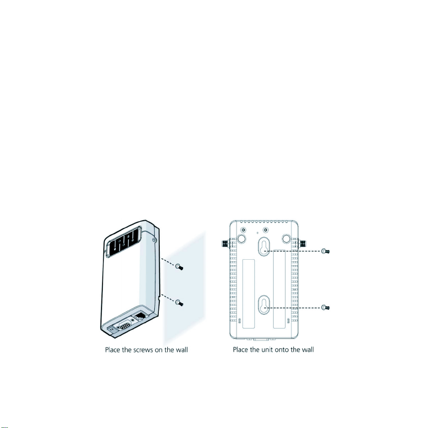
5. Attach the mounting screws to the wall where you made
the holes.
6. Mount the unit onto the wall by fitting the mounting
holes to the screws.
4 BETA P/N: 001287, Rev. 1
Page 5

Draft
Installation
Connecting the Cables
You can provide power to the Fusion 50 either by using the AC
power module or over an Ethernet connection, which utilizes
power-sourcing equipment (PSE).
Note: If you intend to use an Ethernet connection for power,
ensure that the connecting device (that is, a hub or
switch) is Power over Ethernet (PoE) IEEE compliant.
Do the following to connect the cables for the Fusion 50:
Connect the power cable to the power adaptor and then to a
power supply.
Connect the Ethernet cable to the Ethernet port and then to a
client device such as a hub or computer. Again, you can use
an Ethernet connection to provide power to the AP.
At power up, the AP starts a one-minute boot-up sequence. The
Power LED flash green as soon as power is applied. You can
perform initial configuration as soon as the system completes its
boot-up sequence (see “Configuration” on page 6).
Note: To avoid the possibility of a transmission loop, do not
connect an AP that is set in wireless client
(infrastructure) mode directly to the LAN (e.g., through a
wall port or through a hub directly connected to the LAN).
P/N: 001287, Rev. 1 BETA 5
Page 6

Draft
Configuration
Configuration
Prerequisites
Before configuring the Fusion 50 access point, ensure that your
hub or computer is on the same network as the access point and
find the MAC address on the label of the access point (for
example, 00:12:32:A3:81:2c:15).
Creating an AP Template
An AP template is a quick way to configure and activate several
access points discovered on your network.
Do the following to create an AP Template:
1. Start a web browser session.
2. Using HTTP, enter the defined IP address of the controller in
the URL field, for example:
http://192.168.110.104
Note: 192.168.110.104 is the default IP used to start
CompleteMobility Express. If this address does not open
the User Authentication page, contact the technical
support department for U4EA wireless.
6 BETA P/N: 001287, Rev. 1
Page 7

Draft
Configuration
3. Enter your user name (default is admin).
4. Enter your password (default is default).
5. Click Login.
6. Go to Wireless LAN > Controller > Configuration >
Access Points > AP Template tab and check the Basic
radio button.
7. Click Edit.
P/N: 001287, Rev. 1 BETA 7
Page 8

Draft
Configuration
8. Keep the following default settings:
a. Apply to all currently activated APs: No.
b. Automatically activate new APs: No.
c. Apply template to new APs: Yes.
9. In the Long Term Key Seed field, enter a user-defined
32 digit hex key for LTKS. The default value is to enter
1 (one) 32 times.
10. Keep the Radio Preference at its default setting: 2.4
GHz.
11. At this time, do not configure a Tunnel Port Policy.
12. Click the G tab and do the following to configure
transceiver G (2.4 GHz):
a. Keep the default setting for Channel: Auto.
b. Keep the default setting for Allow Stations: Yes.
c. Set Scan for Rogues to No.
13. Click Apply.
8 BETA P/N: 001287, Rev. 1
Page 9

Draft
Configuration
Activating your APs
Next, view and activate all discovered (but inactive) APs on your
network.
Do the following to activate APs:
1. Go to Wireless LAN > Controller > Configuration> Access
Points > New APs tab.
2. Select the APs that you want activated by adding a
check mark in the Select column.
P/N: 001287, Rev. 1 BETA 9
Page 10

Draft
Configuration
3. Check the Activate these APs using the template
radio button.
4. Click Activate.
The system will now use the AP template that you created in
“Creating an AP Template” on page 6 to activate the selected
APs.
5. You can verify that all APs were activated by waiting a
minute and then going to Wireless LAN> Controller >
Configuration > Access Points > Activated APs tab. The
activated APs should now appear.
Note: If this is the first time that you activated an AP, then the
software on the AP upgrades automatically. The AP is
unreachable for about a minute while the software
upgrades.
6. Finally, save the configuration by clicking Save
Configuration located on top of the user interface.
10 BETA P/N: 001287, Rev. 1
Page 11

Draft
Regulator Information
Regulator Information
Pending
P/N: 001287, Rev. 1 BETA 11
Page 12

Draft
Finding Product Documentation
Finding Product Documentation
The CD included with the Fusion 300 has the following
documentation:
Fusion 300 Wireless LAN Hardware Installation Guide
Fusion 50 Access Point Quick Start Guide
CompleteMobility Express 5.0 Web UI Operation Guide
CompleteMobility Express 5.0 CLI Reference Guide
Further documentation may be obtained at the U4EA support site
www.u4eatech.com/support.
12 BETA P/N: 001287, Rev. 1
Page 13

Draft
Downloading the Latest Documentation
Downloading the Latest
Documentation
Updated versions of product documentation can be downloaded
from the support Web site. To download any information from the
support Web site:
1. Go to URL https://support.u4eatechinc.com/
U4EACustomerPortal/LoginForCustomerPortal.asp
2. Login to your account using your login and password. If
authentication is denied, contact support at
support@u4eatech.com
3. Once logged in, browse thorough the items available
under “My Downloads” and double-click on the
document name to start the download.
4. Contact support at support@u4eatech.com
information.
.
for more
P/N: 001287, Rev. 1 BETA 13
Page 14

Draft
454 Kato Terrace
Fremont, CA 94539
www.u4eatech.com
Page 15

Federal Communication Commission Interference Statement
This equipment has been tested and found to comply with the limits for a Class B digital device, pursuant to Part
15 of the FCC Rules. These limits are designed to provide reasonable protection against harmful interference
in a residential installation. This equipment generates, uses and can radiate radio frequency energy and, if not
installed and used in accordance with th e instruction s, may cause harmful interferen ce to radio co mmunications.
However, there is no guarantee that interference will not occur in a particular installation. If this equipment
does cause harmful interference to radio or television reception, which can be determined by turning the
equipment off and on, the user is encouraged to try to correct the interference by one of the following measures:
z Reorient or relocate the receiving antenna.
z Increase the separation between the equipment and receiver.
z Connect the equipment into an outlet on a circuit different from that to which the receiver is connected.
z Consult the dealer or an experienced radio/TV technician for help.
FCC Caution: Any changes or modifications not expressly approved by the party responsible for compliance
could void the user's authority to operate this equipment.
This device complies with Part 15 of the FCC Rules. Operation is subject to the following two conditions: (1) This
device may not cause harmful interference, and (2) this device must accept any interference received, including
interference that may cause undesired operation.
This device and its antenna(s) must not be co-located or operating in conjunction with any other antenna or
transmitter.
If this device is going to be operated in 5.15 ~ 5.25GHz frequency range, then it is restricted in indoor
environment only.
FCC Radiation Exposure Statement:
This equipment complies with FCC radiation exposure limits set forth for an uncontrolled environment. This
equipment should be installed and operated with minimum distance 20cm between the radiator & your body.
 Loading...