

LITE-ON
SEMICONDUCTOR
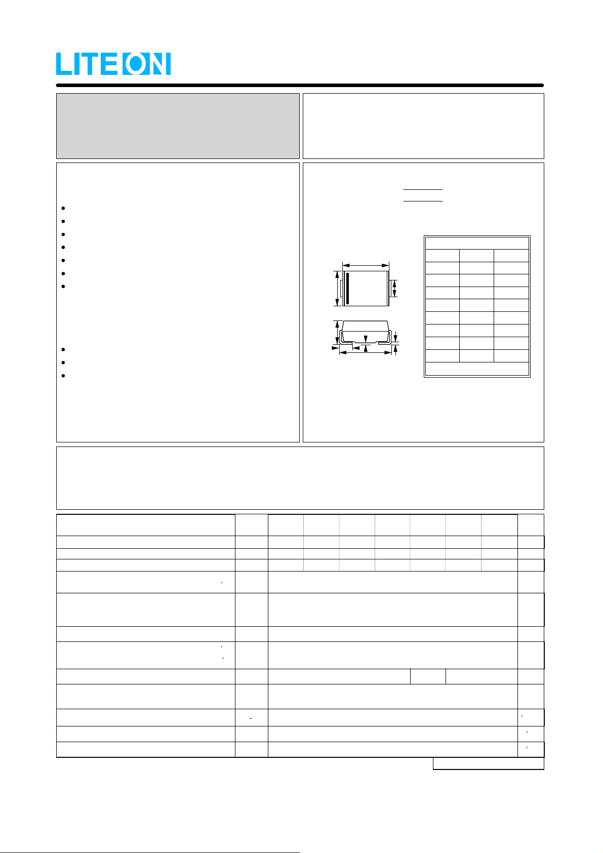
RS1AB thru RS1MB
SURFACE MOUNT
FAST RECOVERY RECTIFIERS
FEATURES
Fast switching for high efficiency
For surface mounted applications
Glass passivated chip
Low reverse leakage current
Low forward voltage drop
High current capability
Plastic material has UL flammability classification 94V-0
MECHANI CAL DATA
Case : Molded plastic
Polarity : Color band denotes cathode
Weight : 0.003 ounces, 0.093 grams
REVERSE VOL TAGE FORWARD CURRENT -
SMB
A
B
G
H
E
C
D
F
DIM. MIN. MAX.
A
B
C
D
E
F
G
H
All Dimensions in millimeter
50 to 1000
1.0
Ampere
SMB
4.06 4.57
1.96
5.21 5.59
0.05 0.20
2.01 2.62
0.76 1.52
Volts
3.94 3.30
2.21
0.31 0.15
MAXIMUM RATINGS AND ELECTRICAL CHARACTERISTICS
Ratings at 25℃ ambient temperature unless otherwise specified.
Single phase, half wave, 60Hz, resistive or inductive load.
For capacitive load, der a te current by 20%
=90 C
=25 C
SYMBOL
RRM
V
RMS
V
DC
V
(AV)
I
FSM
I
F
V
R
I
RR
T
J
C
R
0JL
J
T
STG
T
RS1AB RS1MB RS1KB RS1JB RS1GB RS1DB RS1BB
100
50
70
35
100
50
200
140
200
150 250 500
CHARACTERISTICS
Maximum Recurrent Peak Reverse Voltage
Maximum RMS Voltage
Maximum DC Blocking Voltage
Maximum Average Forward
Rectified Current
Peak Forward Surge Current
8.3ms single half sine-wave
super imposed on rated load (JEDEC METHOD)
Maximum forward Voltage at 1.0A DC
Maximum DC Reverse Current
at Rated DC Blocking Voltage
Maximum Reverse Recovery Time (Note 1)
Typical Junction Capacit ance (Note 2 )
Typical Thermal Resistance (Note 3)
Operating Temperature Range
Storage Temperature Range
@T
@T
@T
L
J
J
=125 C
NOTES : 1.Reverse Recovery Test Conditions :IF=0.5A,IR=1.0A,IRR=0.25A.
2.Measured at 1.0MHz and applied reverse voltage of 4.0V DC.
3.Thermal Resistance Junction to Lead .
UNIT
400
280
400
600
420
600
800
560
800
1000
700
1000
1.0
30
1.3
5.0
200
15
30
pF
C/W
-55 to +150
-55 to +150 C
REV. 2, 01-Dec-2000, KSEB01
V
V
V
A
A
V
uA
ns
C
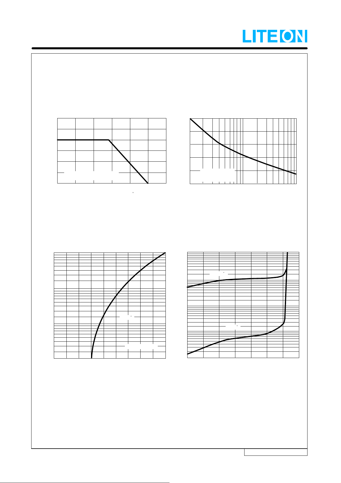
RATING AND CHARACTERISTIC CURVES
RS1AB thru RS1MB
FIG.1 - FORWARD CURRENT DERATING CURVE
1.50
1.25
1.00
0.75
0.50
0.25
SINGLE PHASE HALF WAVE 60Hz
AVERAGE FORWARD CURRENT
AMPERES
RESISTIVE OR INDUCTIVE LOAD
0
25 75 100 125 150
50
LEAD TEMPERATURE , C
FIG.3 - TYPICAL FORWARD CHARACTERISTICS
10
1.0
175
FIG.2 - MAXIMUM NON-REPETI TIVE SURGE CURRENT
30
25
20
15
10
Pulse Width 8.3ms
Single Half-Sine-Wave
(JEDEC METHOD)
5
1
PEAK FORWARD SURGE CURRENT,
AMPERES
2
510
20
50 100
NUMBER OF CYCLES AT 60Hz
FIG.4 - TYPICAL REVERSE CHARACTERISTICS
1000
100
TJ= 125 C
INSTANTANEOUS FORWARD CURRENT, (A)
0.1
.01
0
0.2 0.4
0.6 0.8 1.0
INSTANTANEOUS FORWARD VOLTAGE, (VOLTS)
TJ= 25 C
PULSEWIDTH:300us
1.4
1.2
1.6
1.8
10
REVERSE CURRENT, (uA)
1.0
TJ= 25 C
INSTANTANEOUS
0.1
140
0
20 40
60 80 100
120
PERCENT OF RATED PEAK REVERSE VOLTAGE, (%)
REV. 2, 01-Dec-2000, KSEB01
 Loading...